3D printed threads issue
So I am trying to print some threads, so that two pieces of a project can screw together.
These are 36x4 threads that have been widened to a .2mm tolerance on the inner and outer parts, also filleted.
I have tested twice and cannot seem to get the to print functionally, they will not screw together and have some pretty bad quality overall.
They are both 20mm tall.
Prusa Slicer 25% infill, .2mm layer height, 4 perimeters, what am I missing here? I have to be doing something wrong.
RE: 3D printed threads issue
The angles and bridging are too much for the threads to bind on those tiny little inside holes. Note the size of the extrusion compared to the size of the threads you are trying to print. You're stretching the limits here at that size.
Think about other ways to screw two halves together. Bayonettes. Push pins. Or actual screws.
Think about cutting the threads after printing. For small threads that need to hold actual screws, this approach works great. Printing a thin shaft that you later add threads to - ... that's going to be the icky part. It's a very small surface area (shaft cross section) compared to the outer cutting force needed to put some threads into it - there are sizes of plastic shaft that won't work for this purpose. I think you are near that size.
RE: 3D printed threads issue
@dan-rogers
Ok, thank you!
RE: 3D printed threads issue
So I got the internal threads to print right by switching the perimeters to print the outside first. Opposite of normal. It is printing away perfectly now, but I have a question...
I haven’t found a way to specify that I just want the internal threaded portion (like a nut) to be the only part printed exterior perimeters first. Is that even possible? I tried using a modifier box for perimeters but didn’t see the option to reverse the order specifically for that area (I only saw the options for number of perimeters and what-not).
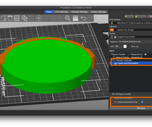
To answer your question, you can use a modifer:
- Right-click on the part.
- Select cylinder (or whatever shape you desire).
- Size the shape to cover the areas of interest.
- Right-click on the shape and select Layers and perimeters.
- Select External perimeters first from the list.
Here's an example with a cutaway threaded piece.
I'm surprised this works, but hey, go for it.
and miscellaneous other tech projects
He is intelligent, but not experienced. His pattern indicates two dimensional thinking. -- Spock in Star Trek: The Wrath of Khan Unfortunately,…
RE: 3D printed threads issue
So I am trying to print some threads, so that two pieces of a project can screw together.
These are 36x4 threads that have been widened to a .2mm tolerance on the inner and outer parts, also filleted.
I have tested twice and cannot seem to get the to print functionally, they will not screw together and have some pretty bad quality overall.
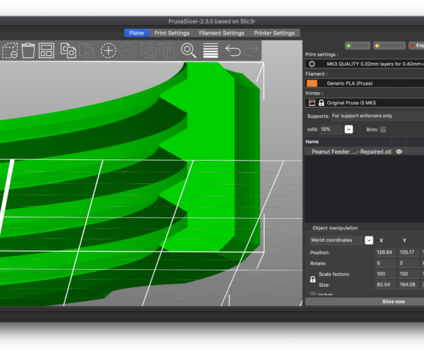
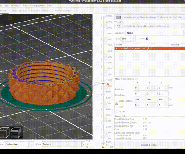
Threads are always a challenge. Depending on the print settings you use, they can create problems with severe overhangs. Here's a cutaway of a threaded adapter I've used:
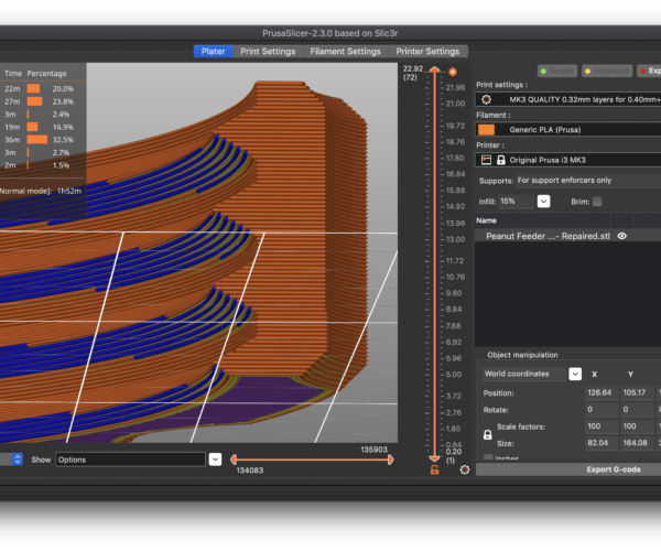
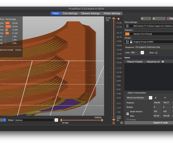
If I select high layer heights and the default width, the blue lines in preview mode clearly show the problem with extreme overhangs. Here's an artificial example with 0.32mm layer heights with 0.45mm extrusion widths. The outer-most perimeters are completely unsupported and highlighted by the slicer as a problem with blue:
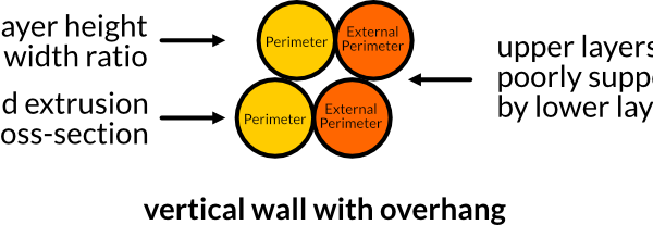
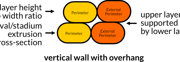
The problem is that the outer-most perimeters are poorly supported and have little inter-layer adhesion with the layers beneath. This is a problem on cylindrical prints as tension is created as the nozzle moves around the interior. The filament is pulled towards the center with tension and can pop loose and create those strings across the opening that you're seeing. When you look at a cross-section, it's easy to visualize why this is a problem (click to see full image):
There are several things you can do. I've found the best overall solution tends to be making sure that your extrusions have a low height-to-width ratio. A wider extrusion will overlap more with the layers below, improving inter-layer adhesion.
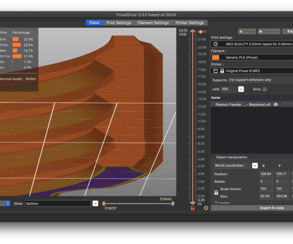
Here's the same print with the same 0.32mm layer height but using a 0.8mm extrusion width. Notice that the thread undersides are no longer showing as overhangs.
If you want a higher quality finish, you can go the other way. Here's the result with a much lower 0.15mm layer height with our original 0.45mm extrusion width:
As you've noticed, you can try other things as well:
- Increasing print temperature or (better) lowering cooling for PLA on the threaded section can allow the hot filament to bond better with what underlying layers it lays on top of. Printing overhangs with PETG, I've added a bit (30%) of cooling fan to keep the overhangs from drooping. Definitely experiment.
- Slower speeds will allow the hot filament to bond better in the same way.
I'm really surprised printing external perimeters first worked for you since those will be the overhanging lines. Not something I'd normally try, but good on ya! If nothing else, this might give some useful information for next time if that doesn't work.
I'm able to print 12mm threaded parts generated in Fusion 360 with good success. It takes a bit of experimentation to get the hang of it, but I haven't had to increase tolerances or use a tap to get good results.
and miscellaneous other tech projects
He is intelligent, but not experienced. His pattern indicates two dimensional thinking. -- Spock in Star Trek: The Wrath of Khan Unfortunately,…
RE: 3D printed threads issue
@bobstro
Thank you for all the suggestions!
I think (and that’s a big think, I’m very green when it comes to 3D printing), that flipping the perimeters in PrusaSlicer still treats the inside external perimeters of the nut as internal perimeters in general (even though they are technically external because it’s an opening), so it printed them last and they had way more material to hang on to as it worked its way in towards the hole in the nut. As in, while I watched it print it would go all around the outside and continue inwards all the way to the center of the nut, it didn’t print the outside of the nut, then the inside tip of the thread, then the inside of those perimeters.
RE: 3D printed threads issue
It's great that you're not just taking anybody's word for things. I always suggest experimenting. I was greatly inspired by Beaker from the Muppet Labs skits on TV and have learned a lot by blowing things up, though mostly figuratively.
Threads are a lot of fun once you master them. I use them a lot for big assemblies. Here's a 14mm bolt and nut I did using the normal Fusion 360 design parameters for threads. I was pleased that no tolerance adjustment in the design or post-processing after the print was required. The nut spins freely and makes a nice fidget toy.
and miscellaneous other tech projects
He is intelligent, but not experienced. His pattern indicates two dimensional thinking. -- Spock in Star Trek: The Wrath of Khan Unfortunately,…
RE: 3D printed threads issue
I was pleased that no tolerance adjustment in the design or post-processing after the print was required. The nut spins freely and makes a nice fidget toy.
@bobstro Your post on layer thickness, fusing layers and inner threads brought light on how to minimise tolerance and still get smooth spinning. You do have tolerance on the fidget toy, don't you? How much? I got to 0.1mm tolerance on powder printed parts from a printhouse (depending on how well cleaned).
RE: 3D printed threads issue
@wetdesign
You will find that tolerances vary according to the orientation of the thread: A part with threads at different angles may need 0.1mm tolerance for a thread in the Z direction but 0.25 in X and as the internal overhangs approach critical angles small changes in intermediate angles may require large changes in tolerance.
Cheerio,
RE:
Hi there, sorry to necro bump but I've created an account just to thank @bobstro for the reply above. I was having the exact same problem and the pictures helped me understand what the problem was and what could I do to solve it.
Just bumping down the layer lines from 0.2 to 0.16 was enough 🙂
Thank you
PS
This is the proof of why foruns like this one are truly superior to social media. This kind of knowledge shouldn't be closed in walled gardens.
RE: 3D printed threads issue
[...] You do have tolerance on the fidget toy, don't you? How much? I got to 0.1mm tolerance on powder printed parts from a printhouse (depending on how well cleaned).
Sorry for the late reply. I just realized that I didn't answer your question.
I'm only using the built-in tolerances that Fusion 360 provides for threads. I use the greatest tolerance provided based on the parameters of the threads, but I don't manually apply any other tolerances or make adjustments for clearance.
and miscellaneous other tech projects
He is intelligent, but not experienced. His pattern indicates two dimensional thinking. -- Spock in Star Trek: The Wrath of Khan Unfortunately,…
RE: 3D printed threads issue
Extrusion width seems to be a good place to start. See animation below
Definitely a good place to start if you want to preserve your layer heights (e.g., for speed of print). You need sufficient overlap between layers for the new layer with overhang to still have sufficient hold on the layer below to prevent sagging from the weight of the extrusion. You can increase extrusion width, and this will work, but keep in mind there may be some features where a wider extrusion width causes problems. It really depends on the specific model you're printing. On a big, chunky functional print, a wider extrusion width will let you get by with higher layers. I wouldn't go too high though as any roughness can cause the threads to lock up badly. A bit of dry Teflon lubricant can help if applied before screwing the parts together.
The big time saver is spending time in slicer preview looking for those blue overhang indicators. Those are a good hint you're going to have printing challenges, and eliminating them as much as possible before hitting print can save a lot of heartache.
and miscellaneous other tech projects
He is intelligent, but not experienced. His pattern indicates two dimensional thinking. -- Spock in Star Trek: The Wrath of Khan Unfortunately,…
RE: 3D printed threads issue
Thanks so much! I was able to solve all my thread printing problems by cutting my layer height in half. IOW, I set it to 1/4 of the nozzle diameter. Truly grateful 😀
RE: 3D printed threads issue
If I select high layer heights and the default width, the blue lines in preview mode clearly show the problem with extreme overhangs. Here's an artificial example with 0.32mm layer heights with 0.45mm extrusion widths. The outer-most perimeters are completely unsupported and highlighted by the slicer as a problem with blue:
The problem is that the outer-most perimeters are poorly supported and have little inter-layer adhesion with the layers beneath. This is a problem on cylindrical prints as tension is created as the nozzle moves around the interior. The filament is pulled towards the center with tension and can pop loose and create those strings across the opening that you're seeing. When you look at a cross-section, it's easy to visualize why this is a problem (click to see full image):
There are several things you can do. I've found the best overall solution tends to be making sure that your extrusions have a low height-to-width ratio. A wider extrusion will overlap more with the layers below, improving inter-layer adhesion.
Here's the same print with the same 0.32mm layer height but using a 0.8mm extrusion width. Notice that the thread undersides are no longer showing as overhangs.
If you want a higher quality finish, you can go the other way. Here's the result with a much lower 0.15mm layer height with our original 0.45mm extrusion width:
This whole page was very helpful. But this part was super helpful for me! Thank you everyone!
