Uneven Prindbed 0.6mm difference in one Corner
Hey there!
For quite some while now my prints and first layers are uneaven (nozzle too close to the printbed, bad first layer) in front right corner of the printbed (~Y:0X:225) which is 0.6mm higher than the rest of the print bed.
To better illustrate the problem here a pic from Bed Visualizer:

This is exactly what i see in my prints, on numerous first layer cals, the layer thickness is too thin/close to the bed.
I have this problem since i have my printer, but only started tinkering with it.
So now to the reason why i seek help and i am out of ideas,
This i have tried to tackle this problem, or at least narrow in on the potential source of error:
The corner is higher with the power coated and spring steel sheet bed, no matter in which orientation.
There is no dirt or dust on the Heatbed, or other parts
Worinkg our way upwards, i aligned the frame and the aluminium extrusions, everything perfectly at 90°
I reprinted the Y carrige rod holders Multiple times, and switched them around.
i canged and later replaced the Y carrige Rods, bearings, ajusted and played with the tension and Alignement of them.
The Y-Carriage was replaced because i thought it might be bent.
I switched the Heatbed spacers around and tried multible ways to tighten the heatbed screws.
The hole extruderbody was upgraded to Rev4 then Rev5, the X carrige rode where changed and the parts reprinted
I tried multible PINDA2 temperatures, with no effect on my problem.
I checkt all magnets, ey sit tight and i see no signe of one of them beeing loos or too deep in the pcb
I have tired multiple PLA, and PETG Filaments.
All of this things had no, to little effect and i am on the edge to change the Heatbed spacers to springs, but is is just a workaround, and will not help me find the core "sickness" of my Y-Carriage.
I havent yet replaced the heatbed and PINDA.
Do you guys have any more Suggestion of things i missed? I'm out of ideas by now.
Thanks in advance, CL
RE: Uneven Prindbed 0.6mm difference in one Corner
Post a photo of a layer one test pattern print: one with small squares printed at nine points. The actual result is far more informative than a plot of "what if" ...
Test patterns can be made pretty easily or downloaded from Thingyverse. But the best have one inch coupons in the four corners, the four midpoints, and one in the center center.
RE: Uneven Prindbed 0.6mm difference in one Corner
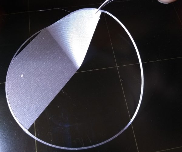
Here's a bed test -- and a cal circle for setting Live-Z. Best to adjust Live-Z at the center of the bed, then run the bed test. The enclosed bed test gcode has full PINDA soak and 7x7x5 mesh level.
RE: Uneven Prindbed 0.6mm difference in one Corner
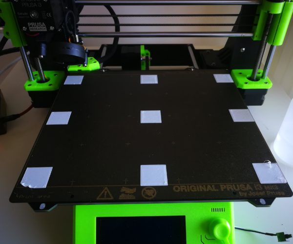
Sorry it took so long, i did a litte vacation in the meantime.
I'm a bit confused about the resaults 🙄
It's always hard to judge from pics, but it looks like you're a bit low (too negative) which causes the nozzle to scrape and deform the top surfaces, tearing a few of them. I'd back off (make less negative) Live-Z by 0.04-0.06 and try again. The top surfaces should be relatively even.
and miscellaneous other tech projects
He is intelligent, but not experienced. His pattern indicates two dimensional thinking. -- Spock in Star Trek: The Wrath of Khan
RE: Uneven Prindbed 0.6mm difference in one Corner
@bobstro
Do you think the thickness of my first layer has anything to do with my uneaven printbed? I rly cannot see the connection between those too.
RE: Uneven Prindbed 0.6mm difference in one Corner
A physically flat bed is important and making an effort to ensure it is flat is worthwhile, temperature variations cause the bed to flex and this variation changes over time and temperature: perfection is hard to achieve.
The photo shows a fairly well corrected bed; as Bob stated, Live-Z is slightly off from what I'd call ideal - it's a bit too negative. The surface should be smooth, not ridged.
The two front corners are lifting due to adhesion, fingerprints most likely.
Thanks! I will play some more with the first layer cal and post an update next week when i'm back home!
But the 0.6mm difference can be due wear? I'm rly concerned that de bed is this much higher in just one corner :/
RE: Uneven Prindbed 0.6mm difference in one Corner
I have my doubts the PINDA is telling you the true state of the bed flatness. It is affected by magnetic fields, temperature variation, and who knows what else: even the density of the plate being measured can affect the proximity result. Then there's the issue the rods holding the X and Y axes are always suspect. Are they true or not? Are the plastic parts holding the rods all exact? E.g., on my printer the X supports are printed vertically, while the extruder is printed horizontally, and I have no idea if all the parts even came off the same production printer at Prusa, so I see variation it height as the X axis moves across the bed that is due not to the bed but to the rods flexing due to the final spacing caused by printer part build accuracy.
If your layer 1 looks good: i.e., even and consistent, count your blessings and move on. If on the other hand you measure a 50mm measurement cube set printed simultaneously on different regions of the bed and find a 0.6 mm height variation based on location, a physical adjustment might be in order (my printer does exactly that - but I am lazy and have yet to do the NyLock mod). It all depends on what you are doing with prints. Artsy? Then actual size accuracy is less important. Samples for other folk? Then scale accuracy is very important.

