Trying to make sense of E (and X/Y/Z)-correction
So I just printed the E-correction gcode from the prusa page, here:
https://help.prusa3d.com/article/p2xdpg0ul8-extruder-linearity-correction-calibration
E-correction was off before I started.
Looking at the end result, the diagonal waves are least visible at the lowest section ("Off"). What does this mean - should I just leave it off, or does it mean my value lies below the minimum in the example (1.03) and I need to try smaller values? It does indeed get less as one goes down the tower.
Also... Are there calibration prints for X/Y/Z correction, and/or a guide for those?
Thanks!
Re: Trying to make sense of E (and X/Y/Z)-correction
Photo ?
In reading the threads, my read is this test is for developers to use to tune settings for inclusion in the firmware. If motor brand changes, then run this test for new values.
Re: Trying to make sense of E (and X/Y/Z)-correction
There's a lengthy discussion here. Unfortunately, the conclusion seems to be "try it and use whatever value works best". If you're not seeing the effect without any adjustment... congratulations!
Re: Trying to make sense of E (and X/Y/Z)-correction
Looking at the end result, the diagonal waves are least visible at the lowest section ("Off"). What does this mean - should I just leave it off, or does it mean my value lies below the minimum in the example (1.03) and I need to try smaller values? It does indeed get less as one goes down the tower.
The XYZE linearity correction values alter the TMC2130 wave table away from being a pure sine wave. If stepper motor mechanics were perfect, a sine wave would result in the most monotonic motion/step. Real life motors may not behave best with a sine wave. This was the topic of a lengthy investigation of TMC tuning for VFA's.
One of the possible alterations in sine wave is to raise it to a power. In the case of what Prusa allows, powers from 1.030 to 1.200 are allowed. We've experimented with powers down to 0.8 and up beyond 1.200 in custom firmware. Values between 0.8 and about 1.020 can sometimes result in zero motion, depending on the motor. That is probably why Prusa only allows a limited range.
The best value may vary from motor to motor even in the same model. The same model will likely cluster around the same value, but your particular unit may differ from average. That is why the print and see method is needed. So, yes. Use the setting that produced the lowest amplitude of diagonal wave. The angle of the diagonal wave you can ignore. That is purely a function of extrusion feedrate vs nozzle feed rate, not a motion regularity based change. Just look at the amplitude.
Set your extruder linearity correction to off if that makes the smallest amplitude diagonal waves. If it is another value (often around 1.100), set that value. NB your setting will NOT store to EEPROM unless you allow the linearity setting menu to exit via time out. Manually exiting the menu does not store to EEPROM.
It is easiest to see non-monotonic step motion on the e-axis with specially constructed objects with thin walls, zero infill, and gcodes that vary the correction power with height. The non-monotonic motion of the motor appears as diagonal waves in such objects. On E, monotonicity issues are spread over a larger distance and become easier to see. These appear (on objects with infill) as a basketweave surface irregularity.
I use my own waveform test towers because to allow other types of filament and examine ranges of settings in x y and e.
These run from 1.030 to 1.200 with changes in X, Y, and E motors. The startup code for these towers differs from standard start. It does meshbed and then there is a pause for hotend heatup. So don't be alarmed by the pause after meshbed. It's not stuck.
Correction values for XY and E increases every 5 mm height. Off at bottom 5 mm, then 1.030, 1.040, 1.050 each 5 mm climb
Diagonal wave shows e-motor effects.
VFA's show X and Y motor effects.
Versions for PETG and PLA are included.

The Prusa supplied ecore tower only varies waveform for only the extruder motor. Just find and use the value that creates the smallest amplitude diagonal wave.
Waveform correction of montonicity is fairly limited on the stock Prusa/LDO motors. Those motors simply have an intrinsic non-monotonicity that repeats every e-cycle. The most significant and effective means of improving monotonicity is to switch to a more monotonic motor. In the absence of changing the motors, linearity correction is the user's only means of action.
What saves the majority of people from seeing the monotonicity issues is random print noise generated by the bearings and rods. That larger noise can largely obscure the smaller artifacts of motor non-monotonicity.
Re: Trying to make sense of E (and X/Y/Z)-correction
Thanks for the additional info. I'll have a go with the other axes just to see what the results are.
Photo ?
I considered adding one but it doesn't photograph well; I'll need to figure out a better lighting setup tonight to see if I can show the effect/result better.
Re: Trying to make sense of E (and X/Y/Z)-correction
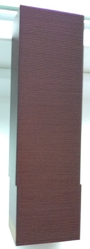
I ran your tower, here's the attached photos.
Perhaps its being masked by the extruder nonlinearity but I'm not seeing very much effect on the X or Y axes. Any vertical effects seem consistent through the height of the tower, regardless of the setting. Looks like your G-code seems to confirm my E setting is best left at off.
Re: Trying to make sense of E (and X/Y/Z)-correction
I agree your e-axis motor does best with linearity correction off.
Can't say much about x and y with all the other noise.
Also, welcome to the club of trying to get the waves to appear on camera. Tough to get the lighting angle right.
Now if I could only get one of these printed on the geared Bondtech extruder.
Also on the cusp of testing different motors more extensively on the extruder, but need to have the Bear extruder STL modified to allow removal of the motor without doing a full extruder tear down. Struggling with Fusion 360 as I'm a total newbie to that. Who would have guessed shifting one existing hole and creating two new ones could be so hard?
I want to have more detailed comparisons of the stock vs LDO cooler, vs Moons 1.8, and Moon 0.9 and OMC 0.9 motors. I'm running into some hints that not only step uniformity within the e-cycle is a factor, but also the torque capability.
Re: Trying to make sense of E (and X/Y/Z)-correction
Also on the cusp of testing different motors more extensively on the extruder, but need to have the Bear extruder STL modified to allow removal of the motor without doing a full extruder tear down. Struggling with Fusion 360 as I'm a total newbie to that. Who would have guessed shifting one existing hole and creating two new ones could be so hard?
Well, probably because STLs are not really practical for technical parts... meshes better lend themselves to organic sculpting. :-/ It's far more viable to edit the SCAD source if one is available as then it is indeed as simple as editing a number that specifies the coordinate.
I edited the PRUSA tower to change the e codes to X/Y codes... will see how that prints. I suppose I could have edited the one here as well, but it takes twice as long to print...
Re: Trying to make sense of E (and X/Y/Z)-correction
Well that was interesting... I had done a regex replace on the gcode and inadvertently swapped out the TMC_STEP_Es for X/ys as well.
Funnily enough, it made my tower print at an angle. Seems like that function adds an offset to the control; I'm guessing it's there in the PRUSA tower to make the pattern more diagonal as the wave function changes, so it's easier to see.
Attempt 2 currently printing... stripped the E commands from the gcode posted here and having a go with that instead.
Re: Trying to make sense of E (and X/Y/Z)-correction
You can build your own variations on the towers. Modify my gcode for before layer change. Just be sure the object your print is thin walled and has NO INFILL. Infill moves the extruder a variable distance between layers and breaks up phase alignment between layers. Change the axes and values as desired.
;BEFORE_LAYER_CHANGE

G92 E0.0
{if layer_z == 5.0}
TMC_SET_WAVE_E30
TMC_SET_WAVE_X30
TMC_SET_WAVE_Y30
{elsif layer_z == 10.0}
TMC_SET_WAVE_E40
TMC_SET_WAVE_X40
TMC_SET_WAVE_Y40
{elsif layer_z == 15.0}
TMC_SET_WAVE_E50
TMC_SET_WAVE_X50
TMC_SET_WAVE_Y50
{elsif layer_z == 20.0}
TMC_SET_WAVE_E60
TMC_SET_WAVE_X60
TMC_SET_WAVE_Y60
{elsif layer_z == 25.0}
TMC_SET_WAVE_E70
TMC_SET_WAVE_X70
TMC_SET_WAVE_Y70
{elsif layer_z == 30.0}
TMC_SET_WAVE_E80
TMC_SET_WAVE_X80
TMC_SET_WAVE_Y80
{elsif layer_z == 35.0}
TMC_SET_WAVE_E90
TMC_SET_WAVE_X90
TMC_SET_WAVE_Y90
{elsif layer_z == 40.0}
TMC_SET_WAVE_E100
TMC_SET_WAVE_X100
TMC_SET_WAVE_Y100
{elsif layer_z == 45.0}
TMC_SET_WAVE_E110
TMC_SET_WAVE_X110
TMC_SET_WAVE_Y110
{elsif layer_z == 50.0}
TMC_SET_WAVE_E120
TMC_SET_WAVE_X120
TMC_SET_WAVE_Y120
{elsif layer_z == 55.0}
TMC_SET_WAVE_E130
TMC_SET_WAVE_X130
TMC_SET_WAVE_Y130
{elsif layer_z == 60.0}
TMC_SET_WAVE_E140
TMC_SET_WAVE_X140
TMC_SET_WAVE_Y140
{elsif layer_z == 65.0}
TMC_SET_WAVE_E150
TMC_SET_WAVE_X150
TMC_SET_WAVE_Y150
{elsif layer_z == 70.0}
TMC_SET_WAVE_E160
TMC_SET_WAVE_X160
TMC_SET_WAVE_Y160
{elsif layer_z == 75.0}
TMC_SET_WAVE_E170
TMC_SET_WAVE_X170
TMC_SET_WAVE_Y170
{elsif layer_z == 80.0}
TMC_SET_WAVE_E180
TMC_SET_WAVE_X180
TMC_SET_WAVE_Y180
{elsif layer_z == 85.0}
TMC_SET_WAVE_E190
TMC_SET_WAVE_X190
TMC_SET_WAVE_Y190
{elsif layer_z == 90.0}
TMC_SET_WAVE_E200
TMC_SET_WAVE_X200
TMC_SET_WAVE_Y200
{elsif layer_z == 95.0}
TMC_SET_WAVE_E0
TMC_SET_WAVE_X0
TMC_SET_WAVE_Y0
{endif}
I did get hold of the fusion files for the extruder. Unfortunately the history didn't go back far enough to move the sketch hole and cause the desired excursions to also move. Having to patch things up the hard way in model, but making progress.
Re: Trying to make sense of E (and X/Y/Z)-correction
Off is best on my MK3S, too.
Re: Trying to make sense of E (and X/Y/Z)-correction
Yep. My print of just the X/Y waveforms finished and I saw no noticeable difference up the length of the tower. So it would seem it doesn't really have an effect on the stock motors. One more thing I can scratch off my list as having tinkered with 🙂
Re: Trying to make sense of E (and X/Y/Z)-correction
I did the test and while very hard to see, the moire does change up the tower. Subtle, and requires a bit of understanding of interference patterns, but there is a change. In any case, I actually prefer the look of a moire over the waves that occur when "properly adjusted" ... lol.
Re: Trying to make sense of E (and X/Y/Z)-correction
The diagonal waves actually are not a moire pattern. The linearity correction towers are constructed to make visible the effect of extrusion motor velocity changes during rotation of that motor. By stacking passes with the extruder motor in near synchrony, the motion artifact can be seen as a diagonal wave. The period of the wave occurs is e-cycle of the extruder motor. If all micro-steps of the cycle yielded equal amounts of extruder feed, there would be no wave. he extrusion rate would be constant. However, a real motor doesn't actually move monotonically with each microstep. Slower motion appears on the tower as troughs. Faster motion creates peaks. That's why the best correction, the one that produces the most monotonic motor motion, is at the setting which yields the smallest peaks and troughs.
PS: Got far enough into Fusion 360 to complete my motor serviceability mods to the Bear extruder. Should soon be able to swap out extruder motors without tearing down the extruder completely. A 15 minute motor swap will make testing of multiple motors on the extruder reasonable.
Re: Trying to make sense of E (and X/Y/Z)-correction
@Guy: re: Moire - yeah, I was wondering why the angle wasn't changing if it were an interference effect. And your non-monotonic extrusion explanation finally clicked.
One of the possible alterations in sine wave is to raise it to a power. In the case of what Prusa allows, powers from 1.030 to 1.200 are allowed. We've experimented with powers down to 0.8 and up beyond 1.200 in custom firmware. Values between 0.8 and about 1.020 can sometimes result in zero motion, depending on the motor. That is probably why Prusa only allows a limited range.
Guy - is the same table used for all axis, or does each axis have it's own? Cable length and driven mass are all factors in resonances... so it would make sense each axis needs it's own table.
I am asking because I am seeing an artifact that a table error would explain fairly well - but it only occurs on the Y-Axis.
Re: Trying to make sense of E (and X/Y/Z)-correction
XYZ & E, each has their own waveform table.
Re: Trying to make sense of E (and X/Y/Z)-correction
XYZ & E, each has their own waveform table.
Yeah - I figured that out; and it confirms the table can cause problems. lol. I get a very nice Y step in the wall ... and it looks just like a giant version of the step I see in other prints.
Red patch at base is facing Front.
Ideas welcome.
Re: Trying to make sense of E (and X/Y/Z)-correction
Breaking news.I just got an amazing result with the $20 OMC 0.9 degree (STEPPERONLINE 0.9° OMC 17HM15-0904S) on the E-axis. I was expecting performance a bit worse than a Moon's 0.9, because it didn't seem to do as well regarding VFA's on Y-axis. At about 1.070-1080, the OMC was able to produce the smallest amplitude diagonal wave I have seen yet. Hold a flash light and looking at the reflection of the light on any other towers and the reflection is smeared vertically. With the OMC, the surface is flat enough that I see a blurry but ROUND image of the flashlight.
Really surprising given that the OMC didn't do that as well removing VFA's. Then again, I didn't vary linearity correction while testing VFA effects because until now, none of the motors actually were better with linearity correction.

From left to right, Moons 1.8, OMC 0.9, Moons 0.9 motors.
I will be doing a more detailed test series on various motors on the e-axis, now that my extruder has been modified to allow fast e-motor changes. It will still take a while to do all the motors, but the tests are now practical.
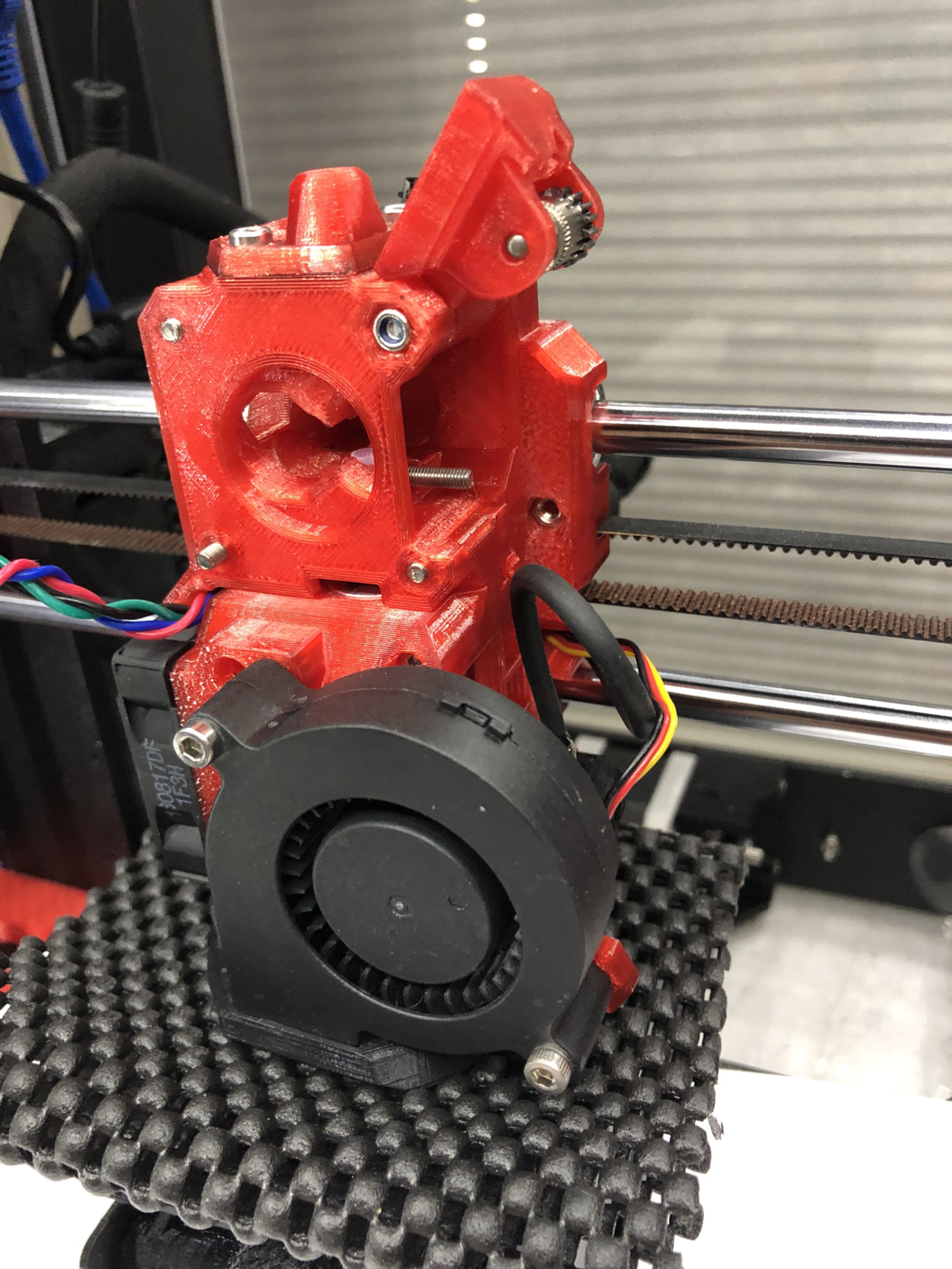
Bear extruder modified to allow motor change without removing fans, cable bundle, or back cover. Just unplug motor, open idler door, and remove three bolts from back of extruder.
Re: Trying to make sense of E (and X/Y/Z)-correction
I wonder how much of this error you are chasing is mechanical - the diameter error in the shaft versus the Bondtech gear. Any out of round will manifest as the wave function you are trying to reduce. A precise fitting gear/shaft interface will minimize the rotational out-of-round feed error.
Said another way - if the gear isn't fitting the shaft perfectly, the set screw will push the gear to one side, creating eccentricity in the gear teeth.
If you have a very good micrometer, I'd be interested in knowing the shaft sizes of the motors you are testing.
Re: Trying to make sense of E (and X/Y/Z)-correction
I wonder how much of this error you are chasing is mechanical - the diameter error in the shaft versus the Bondtech gear. Any out of round will manifest as the wave function you are trying to reduce. A precise fitting gear/shaft interface will minimize the rotational out-of-round feed error.
Very little. The wave period matches the e-cycle, not shaft circumference. We can see that by the second wavelet induced with sine table alterations. It appears midway between the usually existing wave crests.
A circumference related eccentricity would be a much longer wave length and not match e-cycle 1:1
Just for fun some mic'ed diameter measurements tip of shaft to bottom.
Prusa stock
4.994
4.995
4.994
4.996
Moon 0.9
4.994
4.993
4.993
4.989 very bottom of shaft
LDO Cooler 1.8
4.994
4.995
4.994
4.994
The magnitude of variation from motor to motor is far less than needed to create the differences in diagonal wave.
Bondtech ~40 gear tooth intercalation period would be shorter than a full circumference, but still 5 e-cycles long, not 1:1.