PINDA Probe issues
I finished putting my kit together this weekend. I had an issue with a faulty fan and PINDA probe so I hopped in support and went through my issues. There wasn't much trouble shooting, but they offered to send replacement parts. That's great and all, but I dove back into it today and now I'm wondering if the probe is even broken.
The probe lights up red when I run the XYZ calibration. It flickers as it's running the calibration and seems like it stays in off when it doubles back over the calibration point. So I THINK it's actually detecting the calibration point, but maybe not getting the signal back to the motherboard? I've never used inductive sensors before so I'm not well versed in how they work. I understand the basic premise and I see that there's more than 2 pins so I'm assuming that one of those extra pins is some sort of signal wire? Is it possible that the probe functions properly, but the signal wire is broken? If that's the case a quick strip and crimp should fix it, yes?
I just want to make sure I don't sit around waiting for this replacement only to find out it's a firmware issue or something else. If anyone has any insight I'd greatly appreciate it.
Re: PINDA Probe issues
Hi Cody,
raise the extruder to say 60mm
hold a coin against the bottom of the Pinda, the LED on the pinda should go dark,
whilst holding the coin against the bottom of the Pinda, move the extruder from left to right and back again... the pinda led should remain dark...
now remove the coin, and move the extruder from side to side the LED Should remain lit...
there are 4 contacts on the Mk3 prusa's Pinda
they are
+5v
common ground,
Pinda signal wire
Pinda thermistor wire...
it is possible that the Pinda signal wire is broken but the Pinda is otherwise working... this would mean that the tests above work satisfactorily, but the Printer can't see the signal change...
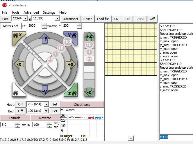
you can use octoprint, or prontaprint to issue an 'M119' command
which will cause the printer to return the current status of the endstops as a snapshot.
in the above picture you can see that I was connected to my printer on COM4 at 115200 baud
I issued the M119 code twice, (input box at the bottom of the page)
the first status showed the Z axis (Z_Min) Open.
the second showed the Z axis (Z_Min) Triggered ... because I was holding a coin to the pinda tip....
if yours doesn't show Triggered, when the LED is dark, the pinda / cable / einsy is faulty. most likely to be the wire in the cable... regards Joan
I try to make safe suggestions,You should understand the context and ensure you are happy that they are safe before attempting to apply my suggestions, what you do, is YOUR responsibility.Location Halifax UK
