Not the ONLY solution, but definitely ONE POSSIBLE solution
A great illustration of the parameter.
Thanks.
I cannot agree with changing the orientation is the key to success with a design with a larger overhang.
I'm not saying it's the only solution, but it is one possible solution that we want in our bag of tricks.
Correction
A great illustration of the parameter.
Thanks.
I cannot agree with changing the orientation is the key to success with a design with a larger overhang.
I'm not saying it's the only solution, but it is one possible solution that we want in our bag of tricks.
Heck that was a typo. Should be: “I cannot agree enough with changing the orientation is the key to success with a design with a larger.”overhang.
--------------------
Chuck H
3D Printer Review Blog
RE: Something's up with your PLA methinks
[...] These are all printed in PLA with the fan at 100%. I’m wondering if I need to get a better cooling fan. I’m running the stock prusa cooling fan. Today I tried printing the same part out of PETG and the results were much better although still not perfect.
Check your spool of PLA. It may have absorbed some moisture. Those results are definitely not typical of what you can get with PLA. I just did a print using my default settings for PLA @ 210C with 0.2mm layer heights with no tweaks and the results are decent:
It's interesting that you get better results with PETG. PETG will tend to be worse due to the lower cooling fan settings in the Prusa profiles. Your PLA filament is a bit suspect at least based on the info seen so far.
It would be nice if designs would take the limitations of FFF printing into account, but your 1st PLA results are not typical. Cooling could be a problem, but the white stuff is really deformed.
@swiss_cheese
however most of these issues can be overcome.
But the degree of tweaking, for a relatively simple object, is excessive. This is one of many designs that just haven't been properly tested before posting where people who don't have your skill are likely to download it. This is an eternal problem and must deter many newcomers to 3D printing. I admit I have no idea how to address it.
Cheerio,
@diem
You seem to be a pretty intelligent person, I would submit to you that you are already addressing it by helping to educate interested people.
That's got to be the answer, and we just have to be careful that we give the best information we can.
This is sth. I am struggling with too. Basically: Fillets that build up. As someone said: this is not designed for FDM, which is true. However, in some cases it is not possible. For instance if you build scale models these kinds of situation occur.
In the picture you see a cabin of an old excavator. It is printed in a few parts. Due to the form of the roof printing parts on the side is the only option. But there is this 5mm radius fillet. I ended up taking out the radius corner and print this standing and glued it in.
I still don't really understand why this is so difficult. When I look at the support structure I saw that PRUSA Slicer (latest version) does not provide support for the first couple of layers. But this is where the problems starts. I think that fillets / radii must be supported. But support must do this in particular in the first couple of layers.
Any other thoughts?
Based on your level of skill relative to 3d modeling and printing, it could be fairly quick to add the supports needed manually to the fillets/radii areas, the support parts can be imported and adjusted to meet the need of the model and make it print beautifully.
Regards
Swiss_Cheese
The Filament Whisperer
@bobstro
I definitely considered that possibility, but the white stuff is a brand new spool and I also had issues with the red filament. Both filaments print everything else really well so I don’t think it’s the actual material. Plus I reprinted the screw file that @swiss_cheese created and it came out perfect with the setting tweaks. I need to learn how to adjust the settings at that skill level to get all my parts to print as perfectly.
Based on your level of skill relative to 3d modeling and printing, it could be fairly quick to add the supports needed manually to the fillets/radii areas, the support parts can be imported and adjusted to meet the need of the model and make it print beautifully.
Good point. I once printed an RC car from 3DSets.com and they used designed-in support. in some places. But I still see this to be challenging.
@asemer
I need to learn how to adjust the settings at that skill level to get all my parts to print as perfectly.
I'll help if I can. I learn & figure out new things in the process also.
@alexander-3
I once printed an RC car from 3DSets.com and they used designed-in support. in some places. But I still see this to be challenging.
If your to continue manufacturing and building your own scale models, or even building those purchased from others, I think you will find the efforts of learning to model in your own supports to be well worth the time. As time goes on it will become less challenging and you will become more prolific.
It was suggested here in this thread that my efforts for these models, "the degree of tweaking, for a relatively simple object, was excessive."
I have to disagree, but not in a derogatory way, but from the point of view that I have a developed skill set that allows me to make these changes in a rapid and flowing way, and so can anyone else who chooses to learn. just the same as you learning to paint your models and apply parts with glue, etc,, these are learned you are not born with them. a persons level of interest will (in my experience) control the level of effort they are willing to expend to learn a new skill.
I am certainly willing to share what I have learned.
Regards
Swiss_Cheese
The Filament Whisperer
RE: Suggestions?
I am certainly willing to share what I have learned.
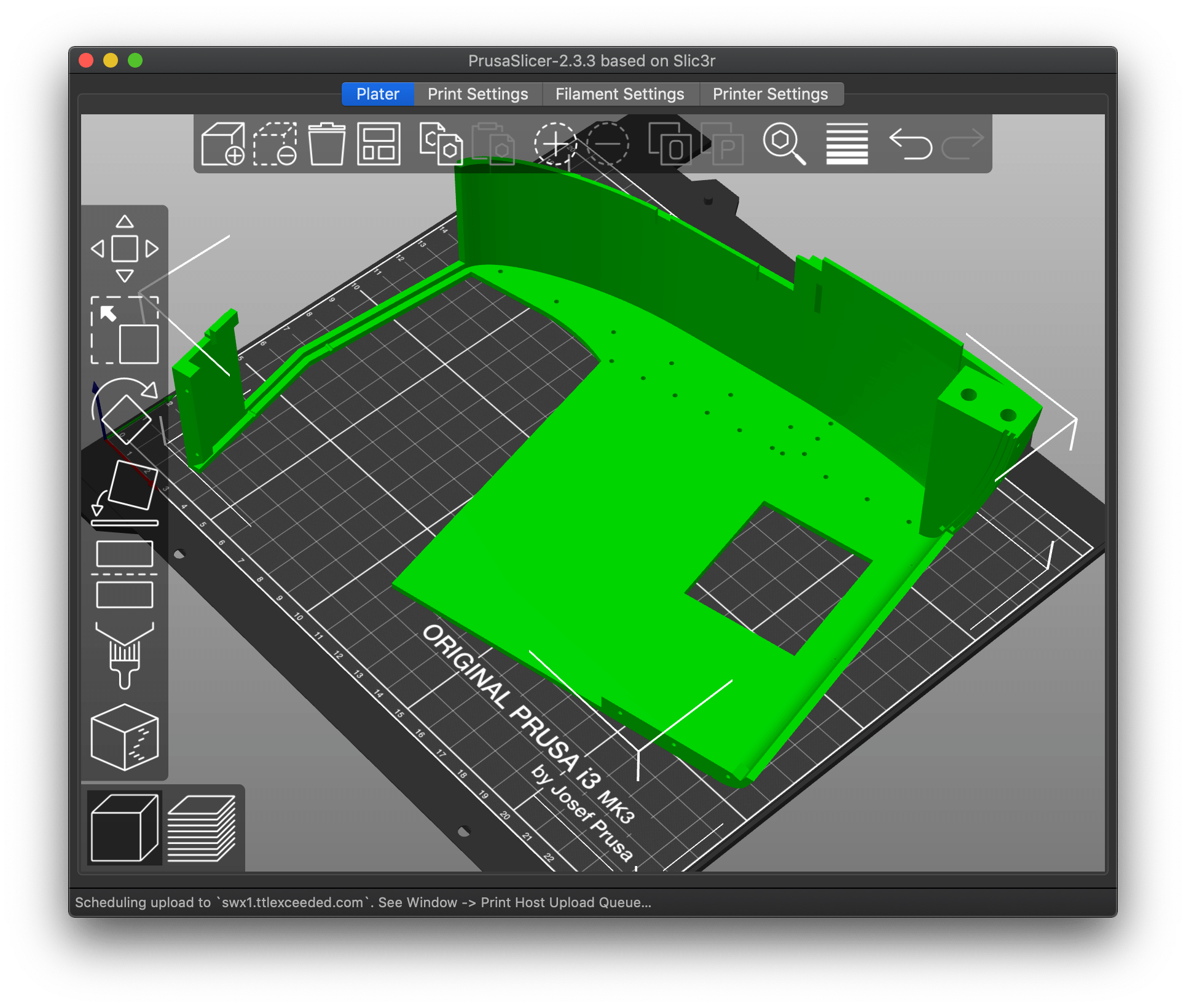
I'll take you by the word. Let's try a simple example. Build a plate 50mm x 50mm x 10mm. On one edge we create a R10 fillet.
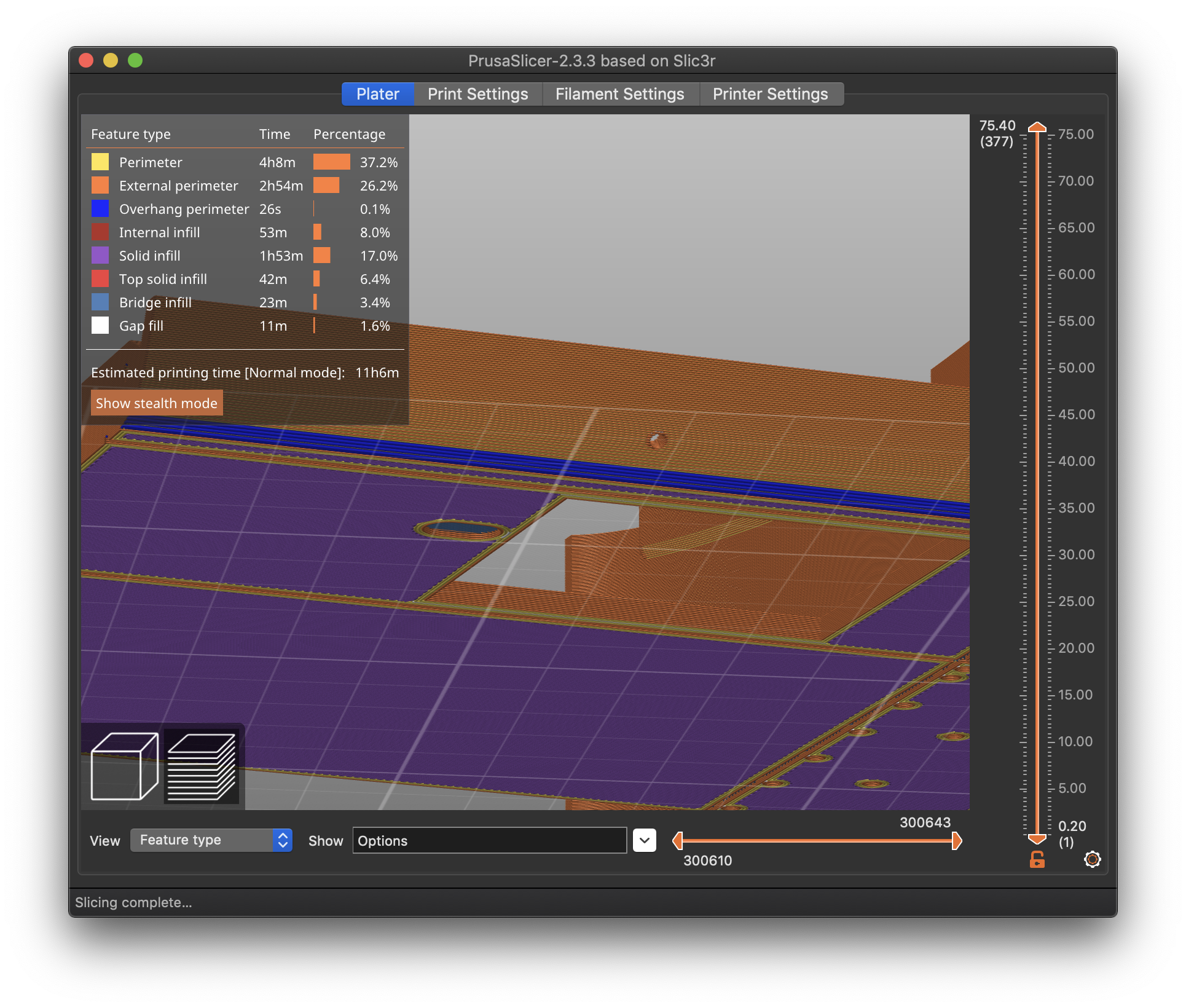
Due to printing constraints (see my excavator) it needs to lie on the side where the filet is rising (see screenshot).
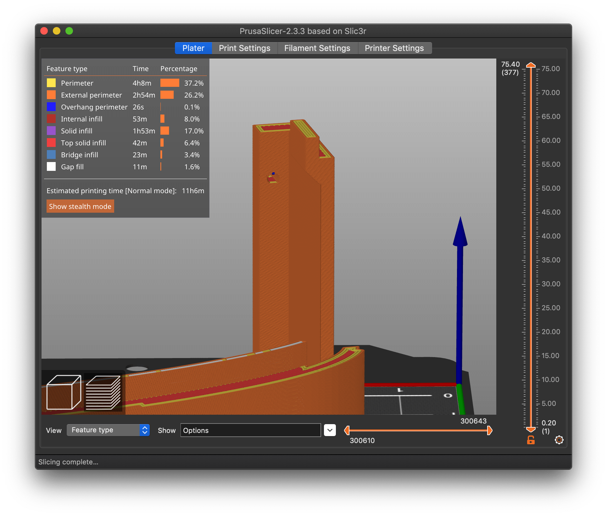
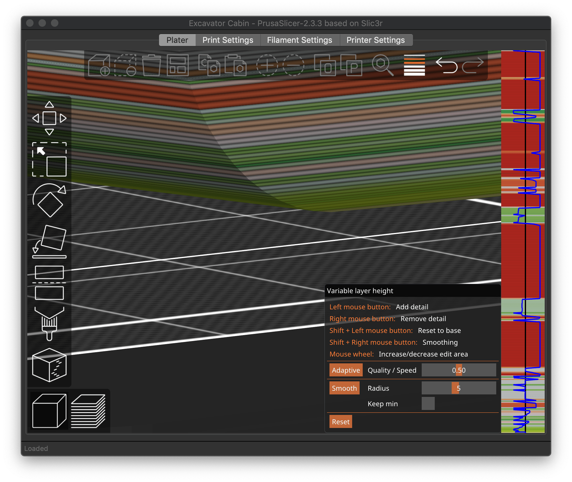
How would you design supports in CAD (F360) that brings great results? If I would add ribs they would be difficult to remove. It is the first 3 layers that are critical. Screenshot 2 shows the 2nd layer where the lines (blue) are printed in mid-air.
I would still think that the supports should be placed automatically.
2nd screenshot
It seems I can only attach one file. Here's the second screenshot.
Drag & drop or batch upload images
It seems I can only attach one file.
You can drag & drop images into the edit area, or upload a batch with the Add Media button above.
STL available?
[...] Due to printing constraints (see my excavator) it needs to lie on the side where the filet is rising (see screenshot).
Can you share the STL or cut down the STL for your excavator to show the exact challenge you're dealing with? It's often easier to deal with specifics than generalities.
How would you design supports in CAD (F360) that brings great results? If I would add ribs they would be difficult to remove. It is the first 3 layers that are critical. Screenshot 2 shows the 2nd layer where the lines (blue) are printed in mid-air.
Looking at your earlier shot, I'd think a thin, easily snapped-off support would work, leading from the vertical wall to the underside of the filleted roof. That, or I'm looking at the wrong bit!
I would still think that the supports should be placed automatically.
Prusa is improving things constantly, so that may happen. They've come a long way when compared to the original Slic3r code base.
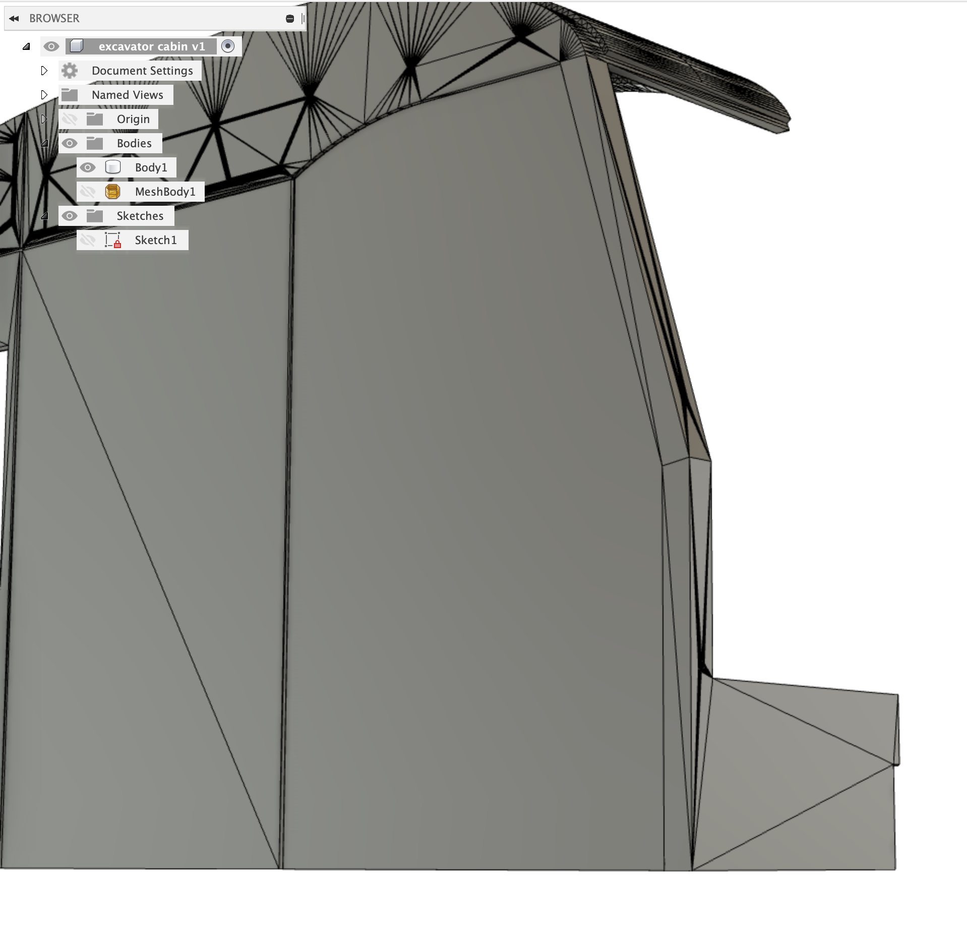
Example
So here's a real life example of one side of my excavator cabin (luckily I could go back in time before I changed the design)
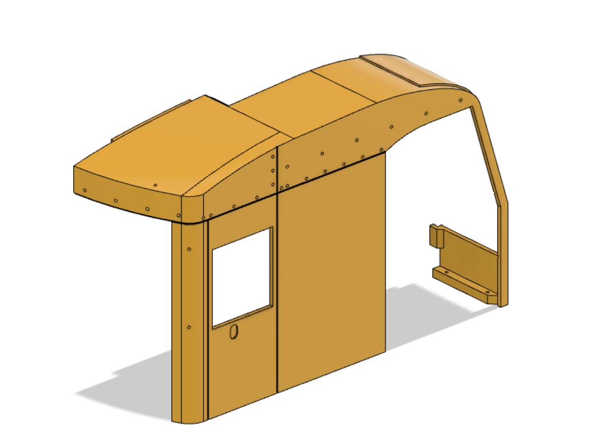
I added the STL as well.
RE: STL
Struggling with attachments. Here it is.
Sorry, it seems I cannot attach STL.
Make sure you rename it so that it ends with .stl. You have to right click and save link or so.
Need to zip attachments
You need to zip up any attachments. Kudos for the work-around.
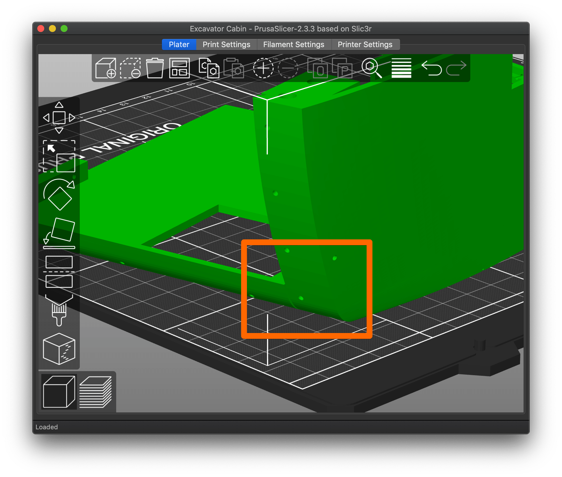
Print orientation and knock-out sacrificial support perhaps?
Would printing it in this orientation work?
The little notch up top looks like it should print well:
There are a few minor overhangs, the biggest challenge being the filleted (of course) underside:
As far as design, if it has to be printed in a sub-optimal orientation, some knock-out sacrificial supports should make it more printable. Here's a rudimentary example:
You'd want to create floor-to-roofline panels wherever there's a tough overhang, so it would print like a hollow inverted box. After printing, those panels can be trimmed out and dressed with a deburring tool cleanly.
Man, I wish I'd had a 3D printer when my kids were little. My oldest loved construction stuff.
RE: Bad overhangs, chamfers, fillets.
Would printing it in this orientation work?
This is the only orientation that can be used. I designed the part for the best possible printability with the least amount of support. Even the tabs don't need support as I used a chamfer. The only problem is the radius in the corner. Everything else works just great. Even the panel lines don't provide problems.
I ended up cutting the corner out in F360 and print it in a standing orientation. So the only "damage" is done in the last 10mm as you can see from the picture of the model further above.
So what's the solution? As an example you can easily design the 50x50x10 part with the fillet on one side that hangs over as also shown above. I am not sure how you want to support this.
Not sure how you want to deal with this.
Cheers Alexander
Extrusion widths and layer heights can help with underside fillets, but they're best avoided


If the result still isn't acceptable, you can try support, but I wouldn't expect much improvement. I'd consider possibly cutting that part out of the main print and printing it fillet-up, then gluing the assembly back together after printing.
Thank you!
Yes, the tabs are excellent. Looking at your original picture, it looks like the STL is the opposite side of the one you uploaded. Is this the corresponding curve on the uploaded sample?
Yes, the cabin is symmetrical. Basically no difference regarding the radius.
You can use a modifier to isolate the changes and/or variable layer height on the problem areas
I used 0,1 mm for the fist 5mm and then switched to 0,15mm as the regular value for the rest.
I'd consider possibly cutting that part out of the main print and printing it fillet-up, then gluing the assembly back together after printing.
That's what I eventually did. You can see in the picture of the original model that only 10mm below the roof is left "ugly" the rest was printed as a single part in standing orientation.
I'll give that a try. Haven't experimented with changing extrusion width. I will cut the part in pieces with Slicer and just print the critical part.
Keep you updated.
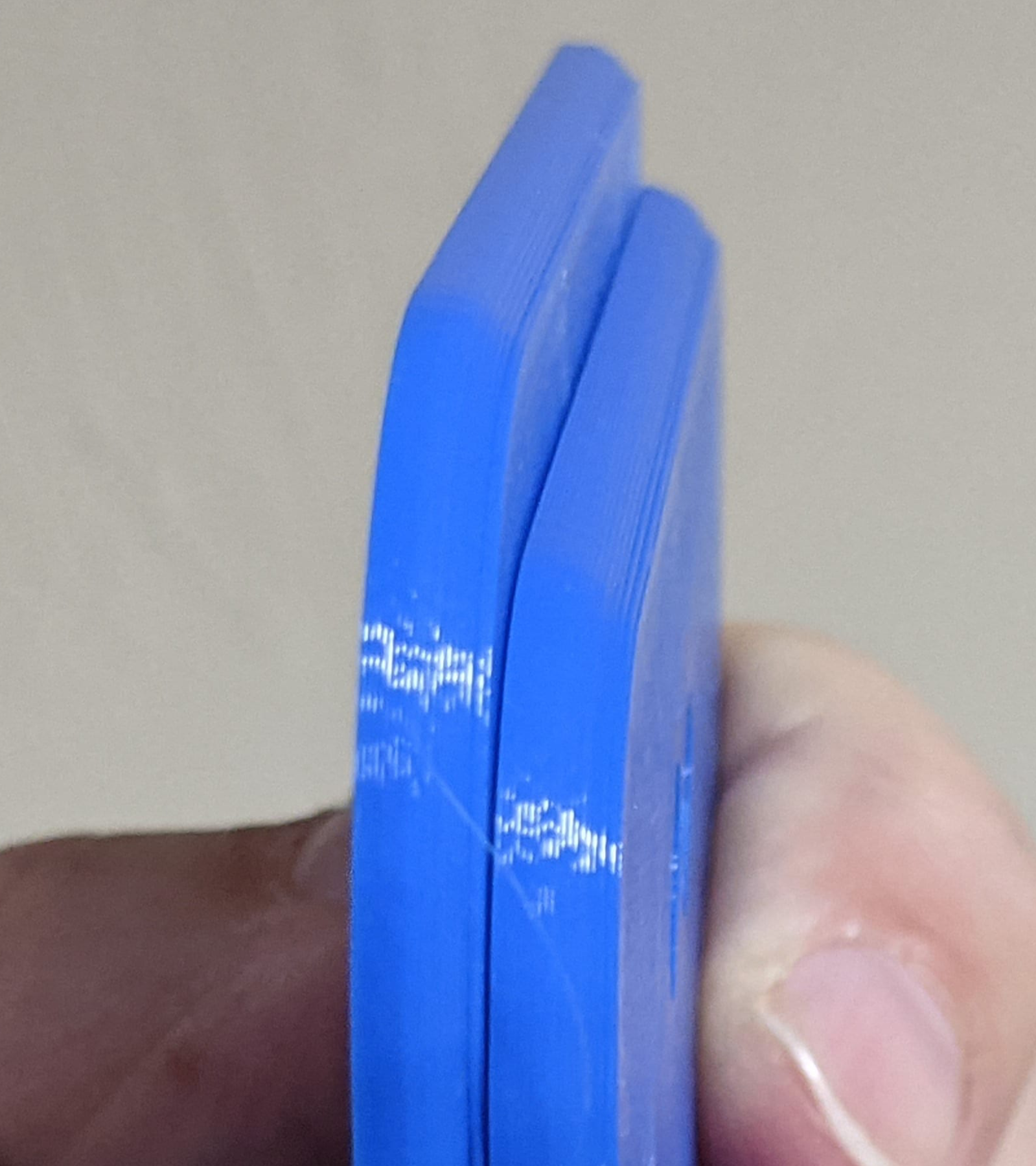
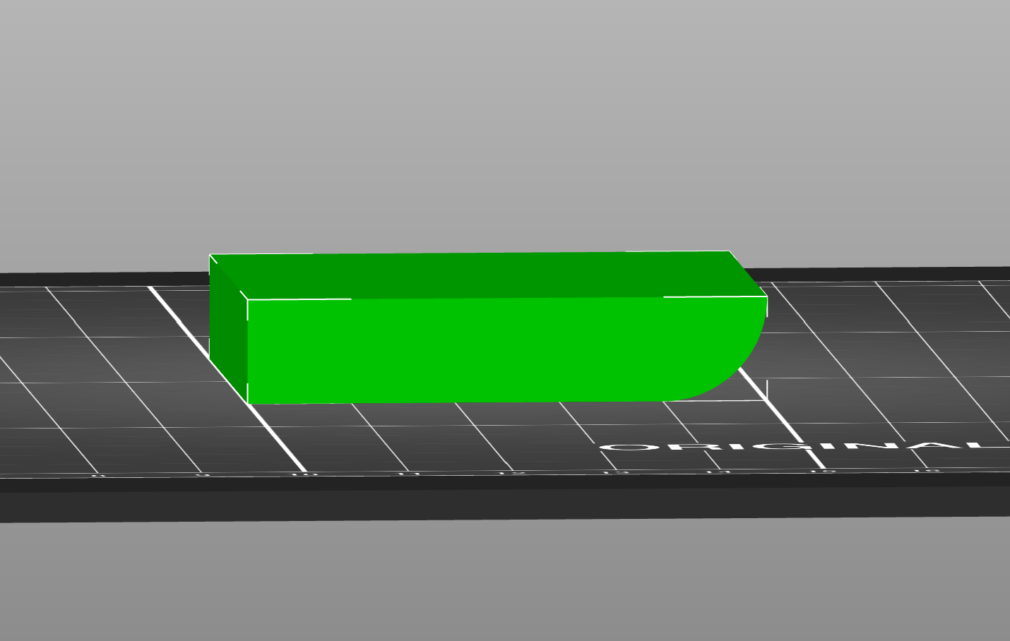
Not 50x50, but 10mm radius
@alexander-3
It is not 50x50, but it is 10mm thick with radius on the bottom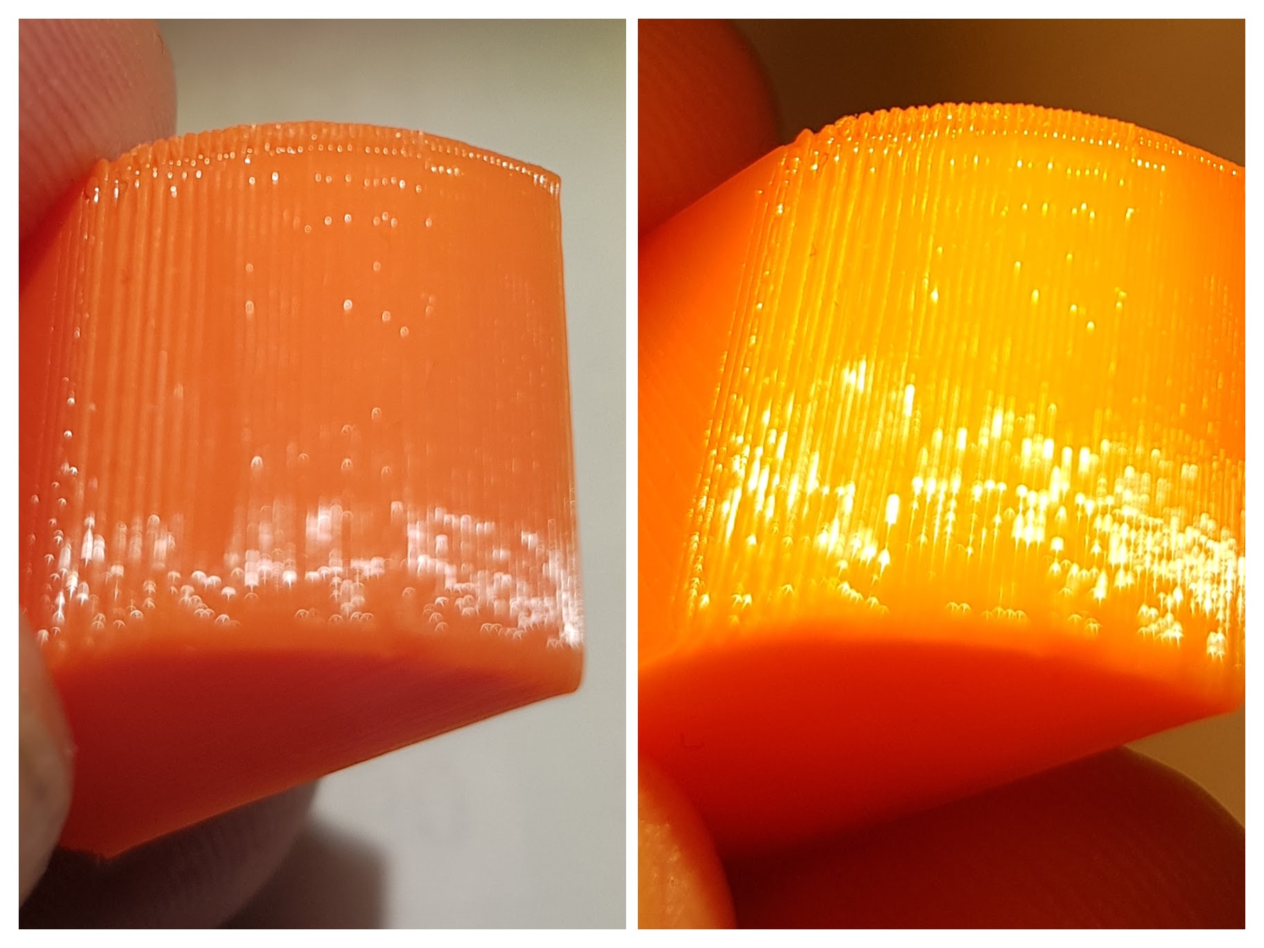
This is done with Prusas 0.20mm QUALITY @MK3, the only changes I was "No Skirt", and some modifiers in Preview
It could easily be tweaked to be much better then this, I see now that you use 0,1 and 0,15, combine that with some changes to extrusion width and some testing, then it will be almost perfect.
Yes, it is done in F360, I could not do it any other way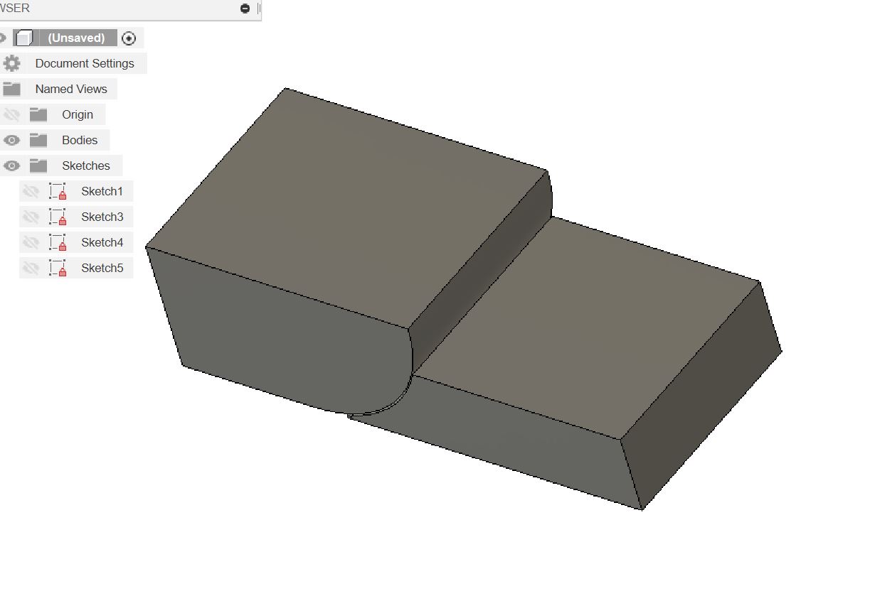
Prusa i3 MK3S+ FW 3.11.0 (kit dec -20), PrusaSlicer 2.6.1+win64, Fusion 360, Windows 10