Re: 1st layer problems - in depth look at software PINDA problems (and solutions!)
I think the 35 degrees is the choice for the minimum value because below this threshold the PINDA does not have significant drift in reading the bed distance. At least in my test using 667 with values below 35 the PINDA output is more or less the same.
I think the choice has been made for the MK2 - where there is an experimental option to actually preheat the PINDA. Since you cannot be sure of the real temperature there I guess they wait for five to ten minutes and depending on the bed temperature they say: it must be 35, or 40, 45 and so on. Just a guess happens there.
In the MK3 this is obsolete and of course it would make sense to account for colder PINDA temperatures. I was hoping to be done with it 🙂 But the preheating still gets on my nerves - so I will dig into the code to make it happen (I guess) - are you guys programing too? Maybe we could co develop it?!
Re: 1st layer problems - in depth look at software PINDA problems (and solutions!)
Should be interesting to do this test to check the pinda behavior below 35c:
assuming that the temp calibration routine is very accurate in determing the correct z distance reading at given temperatur to store the values in eeprom we can temporary change in the source code the standard 40 (35 is assumed 0), 45, 50, 55 and 60 in (for exemple) 20, 25, 30, 35,40 e reading the result value in the serial console.
Probably we can modify the line 3295 and 3301 (to lower the starting bed heating temp.
Just an idea, unfortunately at moment I'm not at home and cannot make any compilation test.
Re: 1st layer problems - in depth look at software PINDA problems (and solutions!)
Yeah that approach should be possible as well, to see how the PINDA does behave in that temperature region.
As the automatic temp calibration was quite unsatisfactory for me (as I said the results I got from manual calibration work perfectly and the automatic results did not work so well) I will try to make a manual calibration for these lower temperatures as well.
The programming I might tackle then. Experimentation first.
Hopefully there will be feedback from Prusa Research available soon/then - maybe they widen the temperature range to accommodate the lower temps themselves. Would save us programming time that I would rather put into USING the machine:-)
But yeah - that preheating is annoying. Because it should not be that way. The good thing is: It will not be like that - no matter what:-)
I love the fact that I bought an open source printer - honestly I did not expect to put so much time into the software aspect of it - but how nice that I CAN.
Re: 1st layer problems - in depth look at software PINDA problems (and solutions!)
Haven't looked at the code, but from the first post it looks like this goes from 35 (0) to 60?
35 > 40 > 45 > 50 > 55 > 60
It also looks like the values (in um) we are seeing in stahlfabrik's calibration steps are a lot smaller than the built in calibration, could we do with bigger jumps in temp but keep the same six fields?
20 > 30 > 40 > 50 > 60 > 70
Or depending on how things react, to cover the high bed temp people:
20 > 40 > 60 > 80 > 100 > 120
Surely that comes up with values for temps in-between right? This would let us calibrate for a wide range, store them in existing storage, and let that calculation do the rest? If it's there. 🙂
EDIT: Bad wording in my part. Obviously we are defining a 6 point curve. Can we figure out the min/max range and divide it by 6 and let the software calculate everything in between? It may not be as accurate, but I am betting it'll be very close.
My MK3 Parts: [Bowden] [New Shoes] [TPU Micro Springs]
Re: 1st layer problems - in depth look at software PINDA problems (and solutions!)
Hi,
I could not get the pinda warmer than 60C so that limit really is OK IMHO!
I also think that the 5C steps are fine. My PINDA is not linear in its behaviour so bigger steps would not be beneficial because of the loss of resolution. I think the only problem is that prints often start with a PINDA that is colder than 35C.
Will there be some kind of algorithmic problem or limitation to use more than the values for 35C to 60C? I do not think so but I just started to think about this problems:-)
I just did two manual calibration tries with 30C and 25C. I used a colder bed than 60C but I do not think this was the best idea because that is quite unrealistic for the MK3. I will likely repeat these measurements but what I saw is quite impressive. There are even bigger jumps than above 35C. Maybe it is because the bed is colder so it is less "bulging" (as in warm things expand) - that is also why I will repeat these measuremts. So here are my measurements:
25 -0,872 (new)
30 -08,45 (new)
35 -0,822
40 -0,810
45 -0,795
50 -0,795
55 -0,787
60 -0,790
So currently my thesis is that in the colder temperature region a lot is happening with the PINDA. A new baseline with 25C would be nice. I do not know if 20C would be the even better baseline. As soon as the hotend starts the PINDA warms too. I use a silicone sock so the effect is less strong, but I do not know. I do not want to suggest a new lower baseline and and then many times for many people the PINDA is even colder than that:-) But I think a new baseline (25C) 10C less than currently (35C) would be a huge improvement and should make most people happy. What do yo think? So I would suggest 25C (always 0 usteps, not in EEPROM) as the baseline and then in EEPROM 30, 35, 40, 45, 50, 55 and 60. So two more values in EEPROM. Or we make 20C the new baseline - if there are no limits that the algorithm or anything imposes here we might as well go there. I think when you let your printer run in a cold room that might even be also a realistic starting temp for the PINDA after hotend and bed have finished heating.
Just a hint: During these tests it takes a long time to cool down the PINDA. Tomorrow I will use ice to make it cool down faster. LOL
Re: 1st layer problems - in depth look at software PINDA problems (and solutions!)
Although it seems to help get a consistent first layer, I'm not happy about having to heat the pinda to 35C since with the bed at 60C and my ambient temp of around 22C, it adds 10-15 minutes to every print.
One potential problem with lowering the calibration range to start at 20 or 25C is that printers running in higher ambient temps wouldn't be able to calibrate at the lower temps without cooling down the pinda somehow, or marking those ranges as uncalibrated and throwing up an error if you ever try to do MBL when the pinda is in an uncalibrated range.
Re: 1st layer problems - in depth look at software PINDA problems (and solutions!)
FYI
Not sure what to make of it.
Re: 1st layer problems - in depth look at software PINDA problems (and solutions!)
Nice Michael!
It is manual versus automatic calibration too, right?
Oh and I have the grey tipped pinda with the grey cable! You others? Which ones do you have?
Re: 1st layer problems - in depth look at software PINDA problems (and solutions!)
stahlfabrik,
M666 S35 ; the new code - wait until PINDA is >= 35C insert temp you wish to calibrate 35, 40, 45, 50, 55 and 60C
stahlfabrik, does your firmware need to be installed to invoke these M666 gcode commands?
Great investigative work by the way. It is much appreciated.
Hi Mark, yes, the M666 and M667 code are not part of the standard firmware. I developed these to be able to do a manual temperature calibration and also preheat the PINDA to a minimum temperature in everyday life.
My firmware also fixes a small bug with a huge impact on the PINDA temperature compensation.
Thank you for the kind words!
Re: 1st layer problems - in depth look at software PINDA problems (and solutions!)
Hello.
Thank you all for your effort and work you invested in PINDA temperature calibration. I am working at Prusa Research and since I was examining PINDA temperature calibration a short while back, I will try to contribute my 2 cents into the discussion. I apologize for lack of response so far.
I will present my personal findings first, then comment on your contribution. You are basically doing very similar experiments that I have done. The current calibration procedure has indeed several major drawbacks, of which I discovered:
1. Bed temperature changes during calibration may be a source of signicifant (!!!) systematic error, especially when the steel sheet is on.
2. Since we are measuring distance in the order of micrometers, the procedure is very sensitive to random measurement errors, vibrations, etc.
3. Due to 2, using interpolating splines may not be the best idea
I made an experimental new calibration procedure, which tries to overcome the issues. It roughly works as follows:
a) Instead of changing bed temperature, I decided to heat the bed all the way up and only after that gradually heat up PINDA by going close to the bed (now at constant temperature). To be on the safe side, steel sheet should be removed beforehand. Also, thermistor and the actual coil may not have the same temperature, some time is therefore assigned for thermal equalization.
b) After getting as many measurements as possible (starting with initial PINDA temperature and ending only after it heats up no more), the data are fitted with straight line (grey PINDAs appear to have linear response)
c) only the coefficients of the fit are saved into EEPROM
d) the calibration is then applied for all temperatures, including those under 35C
e) the reference point of the calibration has been moved to 50C, so the user is never too far from it (which would magnify imperfections of the fit)
This procedure appears to work quite reliably and should be implemented in the next release (next week). For those who want to experiment with it now, check my fork on github (the version is preliminary and e.g. does not properly update the LCD - sorry). This should solve the issues for the grey-cabled PINDAs. For various reasons, PINDAs with black cable have also been used. These have roughly parabolic response, my calibration therefore uses parabolic fit for them. We have not yet properly tested reliability with black PINDAs, though preliminary data seem optimistic. That's roughly the current state of affairs at Prusa Research regarding PINDA temperature calibration. We would love to have implemented that sooner, but there are other issues and our resources are limited.
Regarding your contributions, I have several points to note:
1. As much as I understand it, the bug you discovered is not really a bug, the sign in the FW is correct. The temperature offset has to be subtracted from current z value in order to get the bed shape correctly, as when there is a positive offset, the print head is higher above the bed when PINDA triggers and the bed therefore LOWER than you would deduce from the print head position. When the saved bed levelling value is applied, it is subtracted, so the temp offset is effectively added to the desired z-value. Your claim "...because the PINDA probe triggers lower with increasing temperature." is not correct and is also contradicted by the live adjusted z values that you report. PINDA actually triggers higher when the temperature is higher. The reason why your change did not make matters worse is unclear to me at this point. But since your PINDA is not that temperature dependent, just setting the order of magnitude right might be responsible for the good outcome (switching the sign would mean you are still <30um off). If you have not uncovered the warping bed problem, it could partially compensate for the problem. I don't know. I am also not sure if I correctly understood when you commented/uncommented the "buggy" line of code.
2. I understand the suggested manual calibration works better than original one, likely due to aforementioned issues of the automatic calibration. I have similar experience with "my" calibration (not manual). We wanted to avoid having the user calibrate manually, because it is very user unfriendly and would enable less experienced users to actually make matters worse, not to mention it is virtually impossible to ensure the PINDA stays at the given temperature without changing bed temp while printing. However, in case the new calibration procedure wouldn't work reliably, it is possible we may try to implement manual calibration as well. If we do, it would probably be implemented directly in the menu though, not by special gcodes. It is simply more comfortable and I would also expect that as a user.
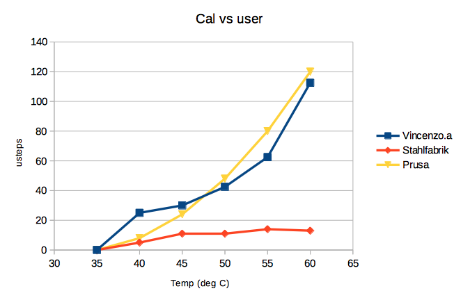
3. The default table may be very incorrect in some cases, you are absolutely right on that one. The reason is (as mentioned) there are unfortunately several versions of the PINDA probe with different characteristics out there. (And even if there weren't, characteristics could still differ a bit from piece to piece and batch to batch.) That is the reason why characteristics in michael.r52's post are that much different. From the look of it, Vincenzo.a has PINDA with a black cable, while Stahlfabrik has grey. Btw, the grey one should have almost perfectly linear response - the flattenning for higher temperature looks very much like what I saw when changing bed temperature during the calibration (as the current calibration procedure does), and I would attribute it to thermal warping of the bed. You can try reversing the process (let the PINDA cool down instead of warm up) or remove the steel sheet - I would not be surprised if the flat part moved to low temperature region or disappeared. In case you wanted to play with it, I strongly suggest you note the bed temperature for each measurement - you are basically going down the same road I did.
To summarize. What you pointed out and what you are discussing is a known issue that has already been invested some time into. Remedy is on the way, we just didn't have enough time to properly implement and test it yet - it will be in the following release. In case anyone decided to try the version from my fork first, we will be happy to hear your feedback. I hope this post will help to uncover what is going on.
PrusaSlicer development
Re: 1st layer problems - in depth look at software PINDA problems (and solutions!)
Thank You Lukas for addressing what Prusa is working on regarding Pinda problems. I think stahlfabrik, should be applauded for all the careful investigation that he has put into this issue. I also look forward to updating my firmware when Prusa releases a new version (I am not a coder and will defer to Prusa to address not just this issue, but consolidate all known issues in upcoming firmware releases).
In the upcoming release then, how is the firmware to know which pinda is mounted in the printer? I have a black one.
Thanks again.
Re: 1st layer problems - in depth look at software PINDA problems (and solutions!)
...
In the upcoming release then, how is the firmware to know which pinda is mounted in the printer? I have a black one.
Thanks again.
The software should easily be able to recognize the order of magnitude difference in output at the temperature extremes between the two probes, then pick the appropriate curve.
Re: 1st layer problems - in depth look at software PINDA problems (and solutions!)
I was starting to wonder where the Prusa folks were on this issue. Thanks Lukas. Looking forward to the new firmware.
Re: 1st layer problems - in depth look at software PINDA problems (and solutions!)
Hello.
Thank you all for your effort and work you invested in PINDA temperature calibration. I am working at Prusa Research and since I was examining PINDA temperature calibration a short while back, I will try to contribute my 2 cents into the discussion. I apologize for lack of response so far.
I will present my personal findings first, then comment on your contribution. You are basically doing very similar experiments that I have done. The current calibration procedure has indeed several major drawbacks, of which I discovered:
<SNIP>
To summarize. What you pointed out and what you are discussing is a known issue that has already been invested some time into. Remedy is on the way, we just didn't have enough time to properly implement and test it yet - it will be in the following release. In case anyone decided to try the version from my fork first, we will be happy to hear your feedback. I hope this post will help to uncover what is going on.
Thanks, Lukas. It's very encouraging to have input from Prusa. As a physicist/engineer/heat transfer guy (retired) who's kit is shipping today, this thread has had me salivating over the opportunity to investigate this topic myself and really celebrating the excellent work that stahlfabrik and the others have done to expose the topic so well to date.
Do keep up the good work on your end and we'll all look forward to benefit from the convergence that can result from such a collaborative exercise.
Re: 1st layer problems - in depth look at software PINDA problems (and solutions!)
Hello Lukas,
It is great to get finally official feedback that really enhances our discussion that we are having here. So thank you, man, much appreciated!
It is great that you (at Prusa Research) are aware of the current shortcomings of the MK3 pinda temperature calibration and that your are working hard to get a better approach to automatic temperature calibration!
I am still not sure though, if you are aware of the severity the problem has (with stock firmware, with or without automatic temperature calibration performed) for me and other users. With the stock firmware I just cannot live adjust Z. Because the PINDA warms during an live adjust Z tuning print the next time the printer runs the live adjust z value is wrong again. It is literally IMPOSSIBLE to get the same first layer twice. When the printer then cools the values are off again. Are you experiencing this behavior in your experiments too? What I am trying to say: Can you replicate our problems in order to verify or falsify a potential bug fix?
I will have a look at your firmware!
But let us talk about your feedback. Especially this first point:
1. As much as I understand it, the bug you discovered is not really a bug, the sign in the FW is correct. The temperature offset has to be subtracted from current z value in order to get the bed shape correctly, as when there is a positive offset, the print head is higher above the bed when PINDA triggers and the bed therefore LOWER than you would deduce from the print head position. When the saved bed levelling value is applied, it is subtracted, so the temp offset is effectively added to the desired z-value. Your claim "...because the PINDA probe triggers lower with increasing temperature." is not correct and is also contradicted by the live adjusted z values that you report. PINDA actually triggers higher when the temperature is higher. The reason why your change did not make matters worse is unclear to me at this point. But since your PINDA is not that temperature dependent, just setting the order of magnitude right might be responsible for the good outcome (switching the sign would mean you are still <30um off). If you have not uncovered the warping bed problem, it could partially compensate for the problem. I don't know. I am also not sure if I correctly understood when you commented/uncommented the "buggy" line of code.
I am really grinding on this. Please allow me to ask: are you really, really sure that the sign is correct? Because many things indicate to me that my bugfix IS working and also that warmer PINDA probes do trigger lower. Please allow me to produce an unordered list of arguments, ideas, experiences:
1. The stock MK3 firmware is hyper temperature sensitive and in my environment (ordinary 18C room) it works "catastrophically" bad regarding the repeatability of the first layer. With my „fix“ and with my manual calibration, I can now print PLA, PETG, ABS without having to change live adjust Z value at all. I do not have to touch it. So my results indicated that my fix SHOULD be correct.
2. Other users in this thread also state that my „fix“ really fixes that same issue for them. I already started to consider this as „proof“ that the sign was wrong.
3. The lines in the original firmware are:
#3756:  float offset_z = 0;

#3758: #ifdef PINDA_THERMISTOR

#3759: offset_z = temp_compensation_pinda_thermistor_offset(current_temperature_pinda);

#3760: #endif //PINDA_THERMISTOR

#3771: mbl.set_z(ix, iy, current_position[Z_AXIS] - offset_z); //store measured z values z_values[iy][ix] = z - offset_z;
About my comment about „uncomment“ a line of code: As said, the stock firmware is hyper temperature sensitive to the point it is really impossible to achieve two times the same first layer in a row. When I commented out line #3759 the problem was MUCH improved. And when I then took line #3759 in again AND inverted the sign I could see that the fluctuations of live Z with variations in temperature were much improved compared to the stock firmware. So I knew that I went in the right direction and now just the temperature calibrations offsets were off (to strong from my observations). So I found my manual calibration approach (which yielded indeed much weaker offsets) and now it works perfectly.
4. I think I SHOULD be right, that the PINDA triggers lower when it gets warmer. E.g.: my 35C live adjust Z value is -0.822 and for 45C it is -0.795 (line #3759 commented out!). What is the same in both cases is the distance from the bed to the nozzle, right? And in the 35C case I dialed the nozzle (aka live adjust z) lower than in the 45C case because the PINDA triggers higher when the pinda is colder. When the PINDA is warmer it triggers lower over the bed, so to achieve the same distance from bed to nozzle live adjust Z has to be less negative (nozzle higher in comparison to z zero). I think my numbers show that - but you state the opposite:-) Put in another way: So that I can set my live adjust to -0.822 and NOT change it when PINDA is 45C the firmware has to internally ADD the offset. So internally it works as if I had live adjusted Z up to -0.795 but I do not have to because the offset is ADDED for me;-)
5. Are you testing with the PEI stickers sheet? Maybe the powder coated sheet hides some of the effects that we are experiencing. Some people have suggested that but I cannot really believe that the hiding is so strong with the other bed composition.
PLEASE consider again if you might be wrong. Just from my experiences everything shows that it works with the inverted sign and is quite catastrophic with the stock firmware:-)
I also am wondering if the homing of the z axis maybe adds to our mutual confusion: Because IMHO the homing of Z is currently NOT temperature compensated, so only mesh bed leveling in relation to uncompensated homing value is temperature compensated. If one would (I am not saying we should!) add a temperature calibration offset (and maybe motor offset movements) to the homing of the Z axis maybe THEN your subtraction of the offset would lead to correct distance from nozzle to the bed - but that is just an idea that hurts my brain to think it through:)
I would so much like to invite you over to show you how my MK3 performs with the stock firmware and the slightest temperature changes. With the „fix“ it works really, really solid - the only thing that I have to pay attention is to not start a print below 35C pinda temperature
.
However, in case the new calibration procedure wouldn't work reliably, it is possible we may try to implement manual calibration as well. If we do, it would probably be implemented directly in the menu though, not by special gcodes. It is simply more comfortable and I would also expect that as a user.
Of course and I totally agree! But I generally think it is a good thing to be able to dial in manual corrections in cases automatisms do not lead to good results. My gcodes really solve the problem for me (but yeah, the things I do in the gcodes would be better imbedded in the firmware (wait for 35C) and in the menu (set offset values). I hope for the best! Oh and also for guys like me who like to repeat the automatic calibration to then calculate mean values so that effects like temporary vibrations etc get nulled out love a way to manually adjust the values that the automatism has found. So it is not badly spend time IMHO to implement that function to the menu
3. The default table may be very incorrect in some cases, you are absolutely right on that one. The reason is (as mentioned) there are unfortunately several versions of the PINDA probe with different characteristics out there. (And even if there weren't, characteristics could still differ a bit from piece to piece and batch to batch.) That is the reason why characteristics in michael.r52's post are that much different. From the look of it, Vincenzo.a has PINDA with a black cable, while Stahlfabrik has grey. Btw, the grey one should have almost perfectly linear response - the flattenning for higher temperature looks very much like what I saw when changing bed temperature during the calibration (as the current calibration procedure does), and I would attribute it to thermal warping of the bed. You can try reversing the process (let the PINDA cool down instead of warm up) or remove the steel sheet - I would not be surprised if the flat part moved to low temperature region or disappeared. In case you wanted to play with it, I strongly suggest you note the bed temperature for each measurement - you are basically going down the same road I did.
You mention some very interesting ideas here. The other guys did the old style automatic calibration (which seems to work OK for them) while I made my „home grown“ manual calibration. For me the automatic calibration did not improve on my problems much. In the PLA range it even made it worse. I do not know which PINDAs they use. By the way: My first MK3 kit had the black PINDA, my replacement has the grey PINDA and both MK3 have the exact same issue which was driving me nearly insane but instead in digesting the source code:-)
Remedy is on the way, we just didn't have enough time to properly implement and test it yet - it will be in the following release.
That is very, very appreciated! But please reconsider the sign again.
Re: 1st layer problems - in depth look at software PINDA problems (and solutions!)
Maybe this is not the right thread to ask this question, but since it involves Pinda temperature and is related to the topic of achieving consistent first layers I'm posting here. In the following M105 via Pronterface response, I'm assuming that the P.38.3 is the current Pinda temperature. I also understand that the first numbers are what the current temps of the extruder and bed are (and their set temps); but what do the numbers after the @ signs mean? And what is the "A" temp number measuring?
T:209.6 /210.0 B:60.1 /60.0 T0:209.6 /210.0 @:91 B@:17 P:38.3 A:33.4
Thanks
Re: 1st layer problems - in depth look at software PINDA problems (and solutions!)
Just to clarify some points (IMHO).
I have the NEW Pinda with grey cable.
I have done just the automatic Temp. Calibration in the Calibration Menu and not the manual procedure explained by stahlfabrik.
Doing the same automatic procedure with the stock firmware I have a noticable inconsistency of first layer depending on Pinda temperature, with worst results at lower temperature <35C.
With the "fixed" firmware as you can clearly see in my previous post I have almost consistent layers starting with a semi-cold PINDA or pre-heated with a 100C bed for an ABS print.
In my personal opinion there should be a better automatic PINDA temperature calibration starting from <25C up to 60C and taking in account of the bed warping. Following the log during the automatic procedure I've seen that the algorithm uses the pinda variation in reading height at the given temperature but doesn't take in account of the bed warping as result of its heating. To be more clear: the first reading is done with bed at 60 and pinda at 35 (example values), and the second with bed at 70 and pinda at 40, then the difference in height (ie. 0.02mm) is used as offset for the pinda drift, but in the same moment also the bed has changed its characteristic resulting in a probably incorrect drift value because contains the pinda drift plus the bed warping. The ideal should be to heat the pinda with an external heater and the bed cold to have an unique drift value not influenced by the bed warping.
Just my two cents.
Vincenzo, Rome
Re: 1st layer problems - in depth look at software PINDA problems (and solutions!)
....but doesn't take in account of the bed warping as result of its heating. To be more clear: the first reading is done with bed at 60 and pinda at 35 (example values), and the second with bed at 70 and pinda at 40, then the difference in height (ie. 0.02mm) is used as offset for the pinda drift, but in the same moment also the bed has changed its characteristic resulting in a probably incorrect drift value because contains the pinda drift plus the bed warping. The ideal should be to heat the pinda with an external heater and the bed cold to have an unique drift value not influenced by the bed warping.
. . . .
Just a thought. Would it help if the bed were heated to 70 while the pinda is not very close to the bed. It seems that the pinda temperature could be "adjusted" by selecting a Z height so that it is farther away from the bed for a lower target pinda temperature and closer for a higher temperature. It could be allowed to stabilize before lowering Z and taking a measurement. As it has some thermal mass, I wouldn't expect its temperature to rise much while taking the reading. This process would allow measurements at different pinda temperatures to be made at a non-changing bed value.
DJ
DJ
Re: 1st layer problems - in depth look at software PINDA problems (and solutions!)
To be more clear: the first reading is done with bed at 60 and pinda at 35 (example values), and the second with bed at 70 and pinda at 40, then the difference in height (ie. 0.02mm) is used as offset for the pinda drift, but in the same moment also the bed has changed its characteristic resulting in a probably incorrect drift value because contains the pinda drift plus the bed warping.
Isn't the whole point of the Pinda to measure the bed at a given temperature to exactly take into account the shape of the bed at that given temperature at that particular time to give the mesh bed leveling the data it needs to compensate for the bed shape via adjusting the Z height to be a constant distance from the bed while laying down the first layers? This is the first principle for having the Pinda. The offsets for Pinda temp are then figured in to the Live Z number, which then in turn is combined with the data the Pinda gathered for the mesh bed level to apply to into the gcode Z values running in the print.