Re: 1st layer problems - in depth look at software PINDA problems (and solutions!)
I do not understand where you are entering and saving your new uStep values of 5, 11, 11,13, &14?
Hi Douglas
You use the M667 gcode:
M667 ? Query the current table
M667 ! Reset the table to default
M667 Z set all values to zero. This is very very handy for manual temperature calibration because it disables temperature compensation.
Finally
M666 S5 I0 sets table Index 0 (aka 40C) to 5 usteps
Is it working for you?
Well not quite yet. I still can’t get the correct height dialed in on the live-z. This has led me to believe that some of the issues I might be experiencing are software related. Things such as first layer height first layer width, stuff like that. There are certain locations in every print I attempt that are always messed up in the very same place every print. It doesn’t matter what the live Z is set to, some of the print is always messed up. So I can’t determine what my setting should be so I can proceed with your instructions for temps higher than 35 degrees. If i can get the first layer looking good I think this process will work. I just have to find the sweet spot and go from there.
EDIT: Added these photos and stuff.
I don't think I am going to get anything better than this. The more I dial it in to make the top left more solid, it messes up the lower right. If I set the first layer to 200%, 150%, 100%, or 90% height the print starts to look good but the lower right corner has a flat piece in it and the top looks see through, as though not much was being extruded. When it is removed from the plate, depending on the LiveZ setting, part of it will be fused together and solid while the other part is just lines of filament attached to the border but not to its neighbors. This is driving me nuts. because without this working correctly, nothing sticks. Everything I print lifts from the bed after 2 hours and the first layer looks horrible.


Re: 1st layer problems - in depth look at software PINDA problems (and solutions!)
great investigation so far, stahlfabrik. You have much more patience than I. 🙂
I'm just glad I do not appear to suffer this problem. I do fiddle with my live-Z (sometimes) when changing from PLA to PETG, for example. But mostly I am able to just print. I noticed you mentioned a grey PINDA. I would describe mine as black. Are there two versions out there?
Thanks a lot! Is your printer in an actively heated chamber?
no.
Re: 1st layer problems - in depth look at software PINDA problems (and solutions!)
did you run temp calibration in menu?
Re: 1st layer problems - in depth look at software PINDA problems (and solutions!)
Me? Yes it is working very bad and made the general situation worse.
There is no way around manual temperature calibration to solve this issues
Re: 1st layer problems - in depth look at software PINDA problems (and solutions!)
Here is a more detailed description on how to do the manual temperature calibration:
Feedback welcome!
Edit:
Here is a small rundown on how to do the manual temperature calibration.
1. choose your material. I recommend Prusa PLA grey.
2. Install my firmware.
3. Optionally set bed level compensation all to zero
4. If you have troubles with a inconsistent bed level maybe do xyz calibration again before you continue. Have your pinda not to cold. Close to 35C would be optimal but that would be impossible for me to do without actively heated chamber. This step is really just optional
5. Use the M666 Z command to zero out the temperature calibration table. Verify with M667 ?. Reboot just to be save. This might be unnecessary!
6. Create gcode files for each temperature level of 35, 40, 45, 50, 55 and 60C. Use a file with a large First Layer in the center of the heatbed so that you have enough time to dial in live adjust z. Edit the files to add the M666 S35 command (example for 35C) after the heater activation. Add the homing gcode before the heater activation. After the M666 you need to home again and do the mesh bed leveling. I added move commandos too: before the heaters start I move z up 5cm. After the heaters have heated up, before the M666 command, I move the nozzle to X5cm Y5cm Z0.15 cm to let the pinda heat up effectively. With pinda Temperatur over 45C you need to raise bed temperature. I used up to 90C.
7. Now start each gcode file and dial in live z each time. Note down each live adjust z value for each pinda temperature. Make sure to dial in the same layer quality each time. I chose to dial in live z down just until the splits between the lines are gone completely. Watch the printers output in pronterface to see what is going on.
8. Now you have the live z values for each temperature. Calculate the offset to the 35C live adjust value which is the base value. Now multiply each offset in mm by 400 to get the offset in usteps
9. Using the M667 Sxx Iy command to set the eeprom to your optimal values. E.g M667 S5 I0 will set 40C offset to 5 usteps.
10. Congratulations. You can now finally enjoy your MK3;-)
Re: 1st layer problems - in depth look at software PINDA problems (and solutions!)
@ douglas.d2
Have you tried this procedure?
https://help.prusa3d.com/l/en/article/TPGip0OmaP-bed-level-correction-kit-only
Re: 1st layer problems - in depth look at software PINDA problems (and solutions!)
@stahlfabrik
I think I've found the right way to operate (at least in my case) to reach the perfect PINDA calibration.
Once corrected the +/- bug in the Marlin_main.cpp source, I found the best way to calibrate the PINDA is using the built in Temp. Calibration of the Prusa firmware. In this way I have reached the best PINDA calibration for each temperature.
I tried your complete procedure using M666 to wait fot correct PINDA temperature for each step and also using only the Temp. Calibration in the menu and I found that the last simply works without any other thing to do.
Thanks to your 667 command the EEPROM value after Temp. Correction procedure are:
>>>M667 ?
SENDING:M667 ?
PINDA cal status: 1
index, temp, ustep, um
n/a, 35, 0, 0.00
0, 40, 10, 25.00
1, 45, 12, 30.00
2, 50, 17, 42.50
3, 55, 25, 62.50
4, 60, 45, 112.50
They are fairly different from those I've found with your manual procedure but also very far from the stock values.
In any case with these value and your fix in the code I have not more any layer thickness difference at all bed temperature, also without waiting after bed heating!
😀
Re: 1st layer problems - in depth look at software PINDA problems (and solutions!)
Hi Great!
Whatever works for you:-)
I am so happy with my manual procedure. I now print ABS and PETG without thinking about live z. Once dialed in I do not have to touch it again.
SUCH a difference than stock behavior where I had to restart prints in average three times until I was halfway satisfied with the first layer...
LOL!!!!!
Re: 1st layer problems - in depth look at software PINDA problems (and solutions!)
I do not understand where you are entering and saving your new uStep values of 5, 11, 11,13, &14?
Hi Douglas
You use the M667 gcode:
M667 ? Query the current table
M667 ! Reset the table to default
M667 Z set all values to zero. This is very very handy for manual temperature calibration because it disables temperature compensation.
Finally
M666 S5 I0 sets table Index 0 (aka 40C) to 5 usteps
Is it working for you?
Well not quite yet. I still can’t get the correct height dialed in on the live-z. This has led me to believe that some of the issues I might be experiencing are software related. Things such as first layer height first layer width, stuff like that. There are certain locations in every print I attempt that are always messed up in the very same place every print. It doesn’t matter what the live Z is set to, some of the print is always messed up. So I can’t determine what my setting should be so I can proceed with your instructions for temps higher than 35 degrees. If i can get the first layer looking good I think this process will work. I just have to find the sweet spot and go from there.
EDIT: Added these photos and stuff.
I don't think I am going to get anything better than this. The more I dial it in to make the top left more solid, it messes up the lower right. If I set the first layer to 200%, 150%, 100%, or 90% height the print starts to look good but the lower right corner has a flat piece in it and the top looks see through, as though not much was being extruded. When it is removed from the plate, depending on the LiveZ setting, part of it will be fused together and solid while the other part is just lines of filament attached to the border but not to its neighbors. This is driving me nuts. because without this working correctly, nothing sticks. Everything I print lifts from the bed after 2 hours and the first layer looks horrible.
IMG_0364.jpgIMG_0365.jpg
Hi Douglas! You say it is always consistent the lower right that is much lower, right? So I would rule out a bad PINDA.
Have you redone XYZ calibration?
Have you looked at your heatbed: is there maybe a screw not turned in completely so that it's head is sticking out?
Have you tried the bed correction - where you can set manually +-50um offsets for the four main bed directions?
Re: 1st layer problems - in depth look at software PINDA problems (and solutions!)
And this is the latest result thanks the exceptional first layer adhesion after the PINDA fix. Exceptional because this is generic ABS without glue, ABS juice, lac, no enclosure, nothing, just a very clean bed. PEI rules, MK3 rules! 😀
You can clearly see the lines of force caused by the cooling in the corners trying to pull up (more white brim) but without any detaching!


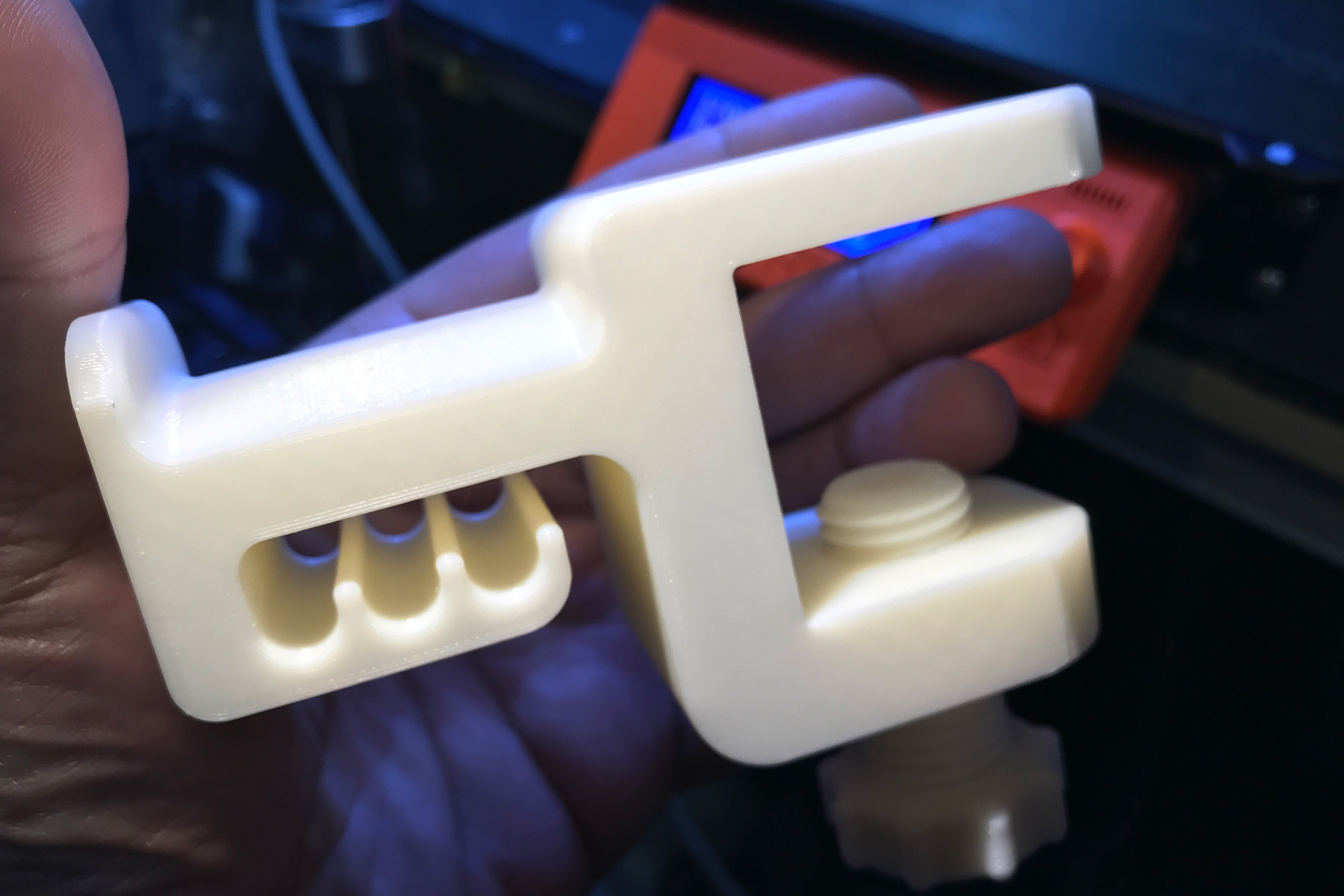
Regards, Vincenzo, Rome
Re: 1st layer problems - in depth look at software PINDA problems (and solutions!)
stahlfabrik,
For constancy and accuracy is this the correct manual temperature calibration Gcode so one only needs to change the PINDA temp ie: temperature level of 35, 40, 45, 50, 55, 60C and increase the bed temp for tests over 45c 🙂
M667 Z ; disable temp calibration make sure bed level correction is set to zero
G28 W ; home all without mesh bed level
G0 Z50 ; raise Z to not heat PINDA before bed is warm
M104 S215 ; set extruder temp
M140 S60 ; set bed temp - raise bed temp up to 90c for PINDA temp test over 45c
M190 S60 ; wait for bed temp
M109 S215 ; wait for extruder temp
G0 X50 Y50 Z0.15 ; this is a good PINDA heating position
M666 S35 ; the new code - wait until PINDA is >= 35C insert temp you wish to calibrate 35, 40, 45, 50, 55 and 60C
G28 W ; home all without mesh bed level
G80 ; mesh bed leveling
G1 Y-3.0 F1000.0 ; go outside print area
G92 E0.0
G1 X60.0 E9.0 F1000.0 ; intro line
G1 X100.0 E12.5 F1000.0 ; intro line
G92 E0.0
M900 K30
The Latest Firmware can be found here https://github.com/prusa3d/Prusa-Firmware/releases
Open Firmware Issues https://github.com/prusa3d/Prusa-Firmware/issues
Re: 1st layer problems - in depth look at software PINDA problems (and solutions!)
YES! So good to see!
Re: 1st layer problems - in depth look at software PINDA problems (and solutions!)
And this is the latest result thanks the exceptional first layer adhesion after the PINDA fix. Exceptional because this is generic ABS without glue, ABS juice, lac, no enclosure, nothing, just a very clean bed. PEI rules, MK3 rules! 😀
You can clearly see the lines of force caused by the cooling in the corners trying to pull up (more white brim) but without any detaching!
Holder1.jpg
Holder2.jpg
Holder3.jpg
Regards, Vincenzo, Rome
Vincenco that is sooo good to see! I am very glad!
Re: 1st layer problems - in depth look at software PINDA problems (and solutions!)
Great work! I’ve been working on some prints that depend on a precise first layer and I’m hoping once this gets in I’ll be closer to achieving that.
Re: 1st layer problems - in depth look at software PINDA problems (and solutions!)
Vincenco that is sooo good to see! I am very glad!
Hey stahlfabrik,
Was talking to nyt in #reprap on irc.freenode.net, and he's merged your fixes into his fork of MK3 firmware: https://github.com/notnyt/Prusa-Firmware/commits/MK3%2BLA%2BPINDA
We were discussing this a bit, is there a reason we need to heat the PINDA up to 35, vs adjusting the code to include a lower temperature range so this can work without heating the PINDA up to the minimum?
My MK3 Parts: [Bowden] [New Shoes] [TPU Micro Springs]
Re: 1st layer problems - in depth look at software PINDA problems (and solutions!)
Vincenco that is sooo good to see! I am very glad!
Hey stahlfabrik,
Was talking to nyt in #reprap on irc.freenode.net, and he's merged your fixes into his fork of MK3 firmware: https://github.com/notnyt/Prusa-Firmware/commits/MK3%2BLA%2BPINDA
We were discussing this a bit, is there a reason we need to heat the PINDA up to 35, vs adjusting the code to include a lower temperature range so this can work without heating the PINDA up to the minimum?
I think heating up is just a workaround. Bigger temp range 25 to 60 should be elegant.
EDIT: So 20C would be base (not saved in EEPROM), ustep value always 0). One would then store to EEPROM 25, 30, 35, 40, 45, 50, 55, 60
I did not look thoroughly into it yet, but I guess one would need to make space for three more int in EEPROM. Obviously without overwriting any other data that is saved there. A factory reset would be needed after firmware update possibly. Or if we are lucky, some sort of transition mechanism could be implemented to populate the new EEPROM addresses - of course only if they are not used yet.
Question: How can we know, if there is space left adjacent to the currently used addresses in EEPROM? Just read them out and see if they contain a 0xff or something like that (the value that the factory reset function writes to EEPROM)? Or is it better to go through "Configuration.h" and see by looking at the defines if there is adjacent space left?
grep "#define EEPROM" *

Configuration.h:#define EEPROM_TOP 4096

Configuration.h:#define EEPROM_SILENT 4095

Configuration.h:#define EEPROM_LANG 4094

Configuration.h:#define EEPROM_BABYSTEP_X 4092

Configuration.h:#define EEPROM_BABYSTEP_Y 4090

Configuration.h:#define EEPROM_BABYSTEP_Z 4088

Configuration.h:#define EEPROM_CALIBRATION_STATUS 4087

Configuration.h:#define EEPROM_BABYSTEP_Z0 4085

Configuration.h:#define EEPROM_FILAMENTUSED 4081

Configuration.h:#define EEPROM_TOTALTIME 4077

Configuration.h:#define EEPROM_BED_CALIBRATION_CENTER     (EEPROM_TOTALTIME-2*4)

Configuration.h:#define EEPROM_BED_CALIBRATION_VEC_X      (EEPROM_BED_CALIBRATION_CENTER-2*4)

Configuration.h:#define EEPROM_BED_CALIBRATION_VEC_Y      (EEPROM_BED_CALIBRATION_VEC_X-2*4)

Configuration.h:#define EEPROM_BED_CALIBRATION_Z_JITTER   (EEPROM_BED_CALIBRATION_VEC_Y-2*8)

Configuration.h:#define EEPROM_FARM_MODE (EEPROM_BED_CALIBRATION_Z_JITTER-1)

Configuration.h:#define EEPROM_FARM_NUMBER (EEPROM_FARM_MODE-3)

Configuration.h:#define EEPROM_BED_CORRECTION_VALID (EEPROM_FARM_NUMBER-1)

Configuration.h:#define EEPROM_BED_CORRECTION_LEFT  (EEPROM_BED_CORRECTION_VALID-1)

Configuration.h:#define EEPROM_BED_CORRECTION_RIGHT (EEPROM_BED_CORRECTION_LEFT-1)

Configuration.h:#define EEPROM_BED_CORRECTION_FRONT (EEPROM_BED_CORRECTION_RIGHT-1)

Configuration.h:#define EEPROM_BED_CORRECTION_REAR  (EEPROM_BED_CORRECTION_FRONT-1)

Configuration.h:#define EEPROM_TOSHIBA_FLASH_AIR_COMPATIBLITY (EEPROM_BED_CORRECTION_REAR-1)

Configuration.h:#define EEPROM_PRINT_FLAG (EEPROM_TOSHIBA_FLASH_AIR_COMPATIBLITY-1)

Configuration.h:#define EEPROM_PROBE_TEMP_SHIFT (EEPROM_PRINT_FLAG - 2*5) //5 x int for storing pinda probe temp shift relative to 50 C; unit: motor steps

Configuration.h:#define EEPROM_TEMP_CAL_ACTIVE (EEPROM_PROBE_TEMP_SHIFT - 1)

Configuration.h:#define EEPROM_BOWDEN_LENGTH (EEPROM_TEMP_CAL_ACTIVE - 2*4) //4 x int for bowden lengths for multimaterial

Configuration.h:#define EEPROM_CALIBRATION_STATUS_PINDA (EEPROM_BOWDEN_LENGTH - 1) //0 - not calibrated; 1 - calibrated

Configuration.h:#define EEPROM_UVLO						(EEPROM_CALIBRATION_STATUS_PINDA - 1) //1 - uvlo during print

Configuration.h:#define EEPROM_UVLO_CURRENT_POSITION	(EEPROM_UVLO-2*4) // 2 x float for current_position in X and Y axes

Configuration.h:#define EEPROM_FILENAME (EEPROM_UVLO_CURRENT_POSITION - 8) //8chars to store filename without extension

Configuration.h:#define EEPROM_FILE_POSITION (EEPROM_FILENAME - 4) //32 bit for uint32_t file position

Configuration.h:#define EEPROM_UVLO_CURRENT_POSITION_Z	(EEPROM_FILE_POSITION - 4) //float for current position in Z

Configuration.h:#define EEPROM_UVLO_TARGET_HOTEND		(EEPROM_UVLO_CURRENT_POSITION_Z - 1)

Configuration.h:#define EEPROM_UVLO_TARGET_BED			(EEPROM_UVLO_TARGET_HOTEND - 1)

Configuration.h:#define EEPROM_UVLO_FEEDRATE			(EEPROM_UVLO_TARGET_BED - 2)

Configuration.h:#define EEPROM_UVLO_FAN_SPEED			(EEPROM_UVLO_FEEDRATE - 1)

Configuration.h:#define EEPROM_FAN_CHECK_ENABLED		(EEPROM_UVLO_FAN_SPEED - 1)

Configuration.h:#define EEPROM_UVLO_MESH_BED_LEVELING     (EEPROM_FAN_CHECK_ENABLED - 9*2)

Configuration.h:#define EEPROM_UVLO_Z_MICROSTEPS     (EEPROM_UVLO_MESH_BED_LEVELING - 2)

Configuration.h:#define EEPROM_UVLO_E_ABS            (EEPROM_UVLO_Z_MICROSTEPS - 1)

Configuration.h:#define EEPROM_UVLO_CURRENT_POSITION_E	(EEPROM_UVLO_E_ABS - 4)                 //float for current position in E

Configuration.h:#define EEPROM_CRASH_DET         (EEPROM_UVLO_CURRENT_POSITION_E - 5)           // float (orig EEPROM_UVLO_MESH_BED_LEVELING-12)

Configuration.h:#define EEPROM_CRASH_COUNT_Y       (EEPROM_CRASH_DET - 1)                       // uint8 (orig EEPROM_UVLO_MESH_BED_LEVELING-15)

Configuration.h:#define EEPROM_FSENSOR           (EEPROM_CRASH_COUNT_Y - 1)                     // uint8 (orig EEPROM_UVLO_MESH_BED_LEVELING-14)

Configuration.h:#define EEPROM_CRASH_COUNT_X       (EEPROM_FSENSOR - 1)                         // uint8 (orig EEPROM_UVLO_MESH_BED_LEVELING-15)

Configuration.h:#define EEPROM_FERROR_COUNT      (EEPROM_CRASH_COUNT_X - 1)                     // uint8 (orig EEPROM_UVLO_MESH_BED_LEVELING-16)

Configuration.h:#define EEPROM_POWER_COUNT       (EEPROM_FERROR_COUNT - 1)                      // uint8 (orig EEPROM_UVLO_MESH_BED_LEVELING-17)

Configuration.h:#define EEPROM_XYZ_CAL_SKEW (EEPROM_POWER_COUNT - 4)                            // float for skew backup

Configuration.h:#define EEPROM_WIZARD_ACTIVE (EEPROM_XYZ_CAL_SKEW - 1)

Configuration.h:#define EEPROM_BELTSTATUS_X (EEPROM_WIZARD_ACTIVE - 2)                          // uint16

Configuration.h:#define EEPROM_BELTSTATUS_Y (EEPROM_BELTSTATUS_X - 2)                           // uint16

Configuration.h:#define EEPROM_DIR_DEPTH        (EEPROM_BELTSTATUS_Y-1)

Configuration.h:#define EEPROM_DIRS  (EEPROM_DIR_DEPTH-80) //8 chars for each dir name, max 10 levels

Configuration.h:#define EEPROM_SD_SORT (EEPROM_DIRS - 1) //0 -time, 1-alpha, 2-none

Configuration.h:#define EEPROM_SECOND_SERIAL_ACTIVE (EEPROM_SD_SORT - 1)

Configuration.h:#define EEPROM_FSENS_AUTOLOAD_ENABLED (EEPROM_SECOND_SERIAL_ACTIVE - 1)

Configuration.h:#define EEPROM_CRASH_COUNT_X_TOT       (EEPROM_FSENS_AUTOLOAD_ENABLED - 2)     // uint16

Configuration.h:#define EEPROM_CRASH_COUNT_Y_TOT       (EEPROM_CRASH_COUNT_X_TOT - 2)          // uint16

Configuration.h:#define EEPROM_FERROR_COUNT_TOT      (EEPROM_CRASH_COUNT_Y_TOT - 2)            // uint16

Configuration.h:#define EEPROM_POWER_COUNT_TOT       (EEPROM_FERROR_COUNT_TOT - 2)             // uint16

Configuration.h:#define EEPROM_TMC2130_HOME_X_ORIGIN           (EEPROM_POWER_COUNT_TOT - 1)                    // uint8

Configuration.h:#define EEPROM_TMC2130_HOME_X_BSTEPS           (EEPROM_TMC2130_HOME_X_ORIGIN - 1)              // uint8

Configuration.h:#define EEPROM_TMC2130_HOME_X_FSTEPS           (EEPROM_TMC2130_HOME_X_BSTEPS - 1)              // uint8

Configuration.h:#define EEPROM_TMC2130_HOME_Y_ORIGIN           (EEPROM_TMC2130_HOME_X_FSTEPS - 1)              // uint8

Configuration.h:#define EEPROM_TMC2130_HOME_Y_BSTEPS           (EEPROM_TMC2130_HOME_Y_ORIGIN - 1)              // uint8

Configuration.h:#define EEPROM_TMC2130_HOME_Y_FSTEPS           (EEPROM_TMC2130_HOME_Y_BSTEPS - 1)              // uint8

Configuration.h:#define EEPROM_TMC2130_HOME_ENABLED            (EEPROM_TMC2130_HOME_Y_FSTEPS - 1)              // uint8

Configuration.h:#define EEPROM_TMC2130_WAVE_X_FAC              (EEPROM_TMC2130_HOME_ENABLED - 1)               // uint8

Configuration.h:#define EEPROM_TMC2130_WAVE_Y_FAC              (EEPROM_TMC2130_WAVE_X_FAC - 1)                 // uint8

Configuration.h:#define EEPROM_TMC2130_WAVE_Z_FAC              (EEPROM_TMC2130_WAVE_Y_FAC - 1)                 // uint8

Configuration.h:#define EEPROM_TMC2130_WAVE_E_FAC              (EEPROM_TMC2130_WAVE_Z_FAC - 1)                 // uint8

Configuration.h:#define EEPROM_TMC2130_X_MRES              (EEPROM_TMC2130_WAVE_E_FAC - 1)                     // uint8

Configuration.h:#define EEPROM_TMC2130_Y_MRES              (EEPROM_TMC2130_X_MRES - 1)                         // uint8

Configuration.h:#define EEPROM_TMC2130_Z_MRES              (EEPROM_TMC2130_Y_MRES - 1)                         // uint8

Configuration.h:#define EEPROM_TMC2130_E_MRES              (EEPROM_TMC2130_Z_MRES - 1)                         // uint8

Configuration.h:#define EEPROM_TMC_AXIS_SIZE  //axis configuration block size

Configuration.h:#define EEPROM_TMC_X (EEPROM_TMC + 0 * EEPROM_TMC_AXIS_SIZE) //X axis configuration blok

Configuration.h:#define EEPROM_TMC_Y (EEPROM_TMC + 1 * EEPROM_TMC_AXIS_SIZE) //Y axis

Configuration.h:#define EEPROM_TMC_Z (EEPROM_TMC + 2 * EEPROM_TMC_AXIS_SIZE) //Z axis

Configuration.h:#define EEPROM_TMC_E (EEPROM_TMC + 3 * EEPROM_TMC_AXIS_SIZE) //E axis

Configuration.h:#define EEPROM_TMC_X_USTEPS_INTPOL   (EEPROM_TMC_X +  0) // 1byte, bit 0..4 USTEPS, bit 7 INTPOL

Configuration.h:#define EEPROM_TMC_X_PWM_AMPL        (EEPROM_TMC_X +  1) // 1byte (0..255)

Configuration.h:#define EEPROM_TMC_X_PWM_GRAD_FREQ   (EEPROM_TMC_X +  2) // 1byte, bit 0..3 GRAD, bit 4..5 FREQ

Configuration.h:#define EEPROM_TMC_X_TCOOLTHRS       (EEPROM_TMC_X +  3) // 2bytes (0..)

Configuration.h:#define EEPROM_TMC_X_SG_THRS         (EEPROM_TMC_X +  5) // 1byte, (-64..+63)

Configuration.h:#define EEPROM_TMC_X_CURRENT_H       (EEPROM_TMC_X +  6) // 1byte, (0..63)

Configuration.h:#define EEPROM_TMC_X_CURRENT_R       (EEPROM_TMC_X +  7) // 1byte, (0..63)

Configuration.h:#define EEPROM_TMC_X_HOME_SG_THRS    (EEPROM_TMC_X +  8) // 1byte, (-64..+63)

Configuration.h:#define EEPROM_TMC_X_HOME_CURRENT_R  (EEPROM_TMC_X +  9) // 1byte, (-64..+63)

Configuration.h:#define EEPROM_TMC_X_HOME_DTCOOLTHRS (EEPROM_TMC_X + 10) // 1byte (-128..+127)

Configuration.h:#define EEPROM_TMC_X_DTCOOLTHRS_LOW  (EEPROM_TMC_X + 11) // 1byte (-128..+127)

Configuration.h:#define EEPROM_TMC_X_DTCOOLTHRS_HIGH (EEPROM_TMC_X + 12) // 1byte (-128..+127)

Configuration.h:#define EEPROM_TMC_X_SG_THRS_LOW     (EEPROM_TMC_X + 13) // 1byte, (-64..+63)

Configuration.h:#define EEPROM_TMC_X_SG_THRS_HIGH    (EEPROM_TMC_X + 14) // 1byte, (-64..+63)

Configuration.h:#define EEPROM_FIRMWARE_VERSION_END       (FW_PRUSA3D_MAGIC_LEN+8)

Configuration.h:#define EEPROM_FIRMWARE_VERSION_FLAVOR    (FW_PRUSA3D_MAGIC_LEN+6)

Configuration.h:#define EEPROM_FIRMWARE_VERSION_REVISION  (FW_PRUSA3D_MAGIC_LEN+4)

Configuration.h:#define EEPROM_FIRMWARE_VERSION_MINOR     (FW_PRUSA3D_MAGIC_LEN+2)

Configuration.h:#define EEPROM_FIRMWARE_VERSION_MAJOR     FW_PRUSA3D_MAGIC_LEN

Configuration.h:#define EEPROM_FIRMWARE_PRUSA_MAGIC 0

Configuration.h:#define EEPROM_OFFSET 20 //offset for storing settings using M500

Configuration.h://#define EEPROM_OFFSET

Configuration.h://#define EEPROM_SETTINGS

Configuration.h://#define EEPROM_CHITCHAT

ConfigurationStore.cpp:#define EEPROM_WRITE_VAR(pos, value) _EEPROM_writeData(pos, (uint8_t*)&value, sizeof(value))

ConfigurationStore.cpp:#define EEPROM_READ_VAR(pos, value) _EEPROM_readData(pos, (uint8_t*)&value, sizeof(value))

ConfigurationStore.cpp:#define EEPROM_OFFSET 20

ConfigurationStore.cpp:#define EEPROM_VERSION "V2"

ConfigurationStore.h:#define EEPROM_SETTINGS
Then several functions have to be patched to accommodate the larger range of values. Mesh bed leveling, automatic temperature calibration... And I have no idea in what way then these changes brake compatibility to what has been implemented for the MK2. But it should be feasible.
EDIT 2: Looking at the code I just pasted it is obvious to me now that: there is no adjacent space left so a factory reset is needed. But so be it...
Re: 1st layer problems - in depth look at software PINDA problems (and solutions!)
I will try the coming nights to do manual temperature calibration for 20C, 25C and 30C to see how these values should be set.
Could you all do the same please, and lets share our values. While we are digging into these problems we could as well generate a set of better suited default values for everyone to use by factory defaults...
Re: 1st layer problems - in depth look at software PINDA problems (and solutions!)
I think the 35 degrees is the choice for the minimum value because below this threshold the PINDA does not have significant drift in reading the bed distance. At least in my test using 667 with values below 35 the PINDA output is more or less the same.
This is what I was expecting as well, but we are seeing that we have to preheat it to 35 to get accurate results, which makes me think that isn't the case. If we set the low end to include ambient temps, we may be able to skip the pinda preheat altogether?
My MK3 Parts: [Bowden] [New Shoes] [TPU Micro Springs]
Re: 1st layer problems - in depth look at software PINDA problems (and solutions!)
From my experiences yesterday - I was printing PETG and forgot to preheat the PINDA - I am also quite sure that the offsets will change below 35 - otherwise the print should have been perfect but it was too high (as expected).
Because above 35 - I must say - they turn out the same now every time.