Poor surface above supports
Hello,
I open this post because I can't solve a serious problem.
I use Simplify 3D as a slicing program, and can't print my models in any way, with good quality layers in contact with the supports.
These are my current settings (mold always with a layer height of 0.1/0.15mm):

This is the best result I've managed to achieve, but I'm not absolutely satisfied! Even a friend of mine who owns an MK3 can't solve the problem. Is it possible that the Prusa i3 MK3 can't achieve good quality?

Has anyone managed to solve this problem? Can you help me?
Re: Poor surface above supports
I can't read Italian, so I'm guessing here, but it looks like your support offset may not be close enough to the model. I usually set mine to 0.1mm for PLA, and 0.05mm for PETG. That said, the mating surface of supports to the model is always going to be pretty nasty, unless you print with soluble supports and a 0 offset. I usually try not to print curved surfaces down on the print bed when possible for this reason.
Re: Poor surface above supports
It is a limitation of current FDM printer technology. If your supports have 0% clearance between support and print, they'll be difficult or impossible to remove unless you use dissolvable supports. If you add clearance, the material immediately above supports is essentially printing on air, so there won't be any filament squish and it will be prone to a bit of dropping (down to the supports worst case). Bridged surfaces will have the same issues.
[...] Even a friend of mine who owns an MK3 can't solve the problem. Is it possible that the Prusa i3 MK3 can't achieve good quality?
You can play with the Z gap between supports and model, but you're simply trading off one problem for another. You may be able to get somewhat better looking supported surfaces, but you're not likely to get good looking supported surfaces. You're better off either investing in a multi-extruder setup that can handle dissolvable supports, or working to avoid needing supports at all. If you really can't have rough surfaces, you probably don't want an FDM printer. It may change in 6 months or 6 years, but there are limits to FDM technology today.
Re: Poor surface above supports
I understand....
Does anyone have experience with the multi extruder for MK3? Is it well functional? Would using a PVA solve the problem?
Re: Poor surface above supports
I think (assuming my guess of Italian is correct) you can lower the vertical support offset. On my mk3 with PETG (i.e. even stickier than PET) I can use a distance of 0.16mm without the part sticking. If you are using 0.40mm I bet you can go a lot closer (less sagging).
Re: Poor surface above supports
I've got the MMUv2 on order and a spool of water-soluble support filament ready. Not available yet unfortunately.
[...] Does anyone have experience with the multi extruder for MK3? Is it well functional? Would using a PVA solve the problem?
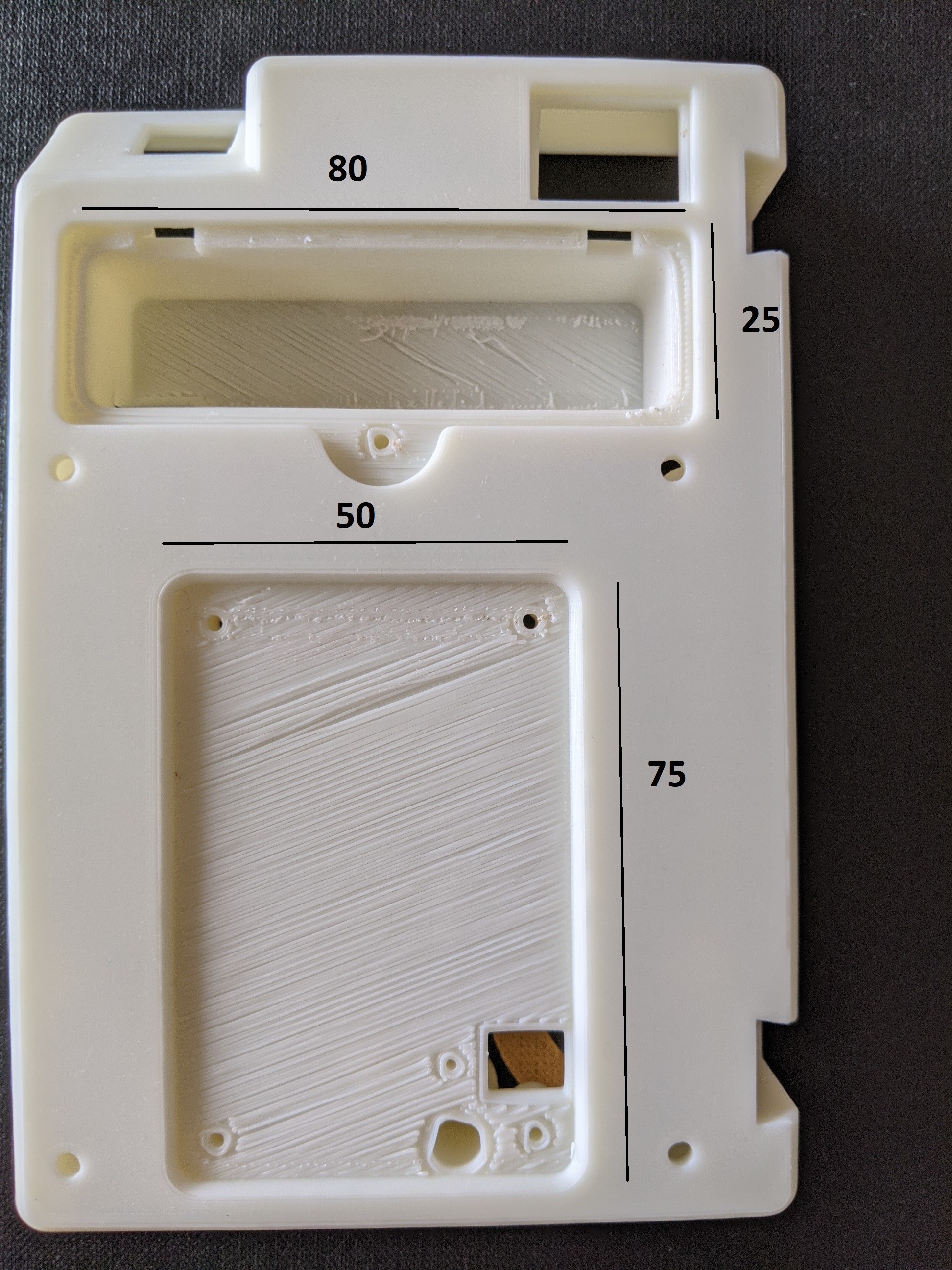
Re: Poor surface above supports
This is about the best surface I have been able to achieve over support structure. The part is shown upside down relative to how it was printed. The horizontal surface is the surface which was printed on the support. Orthogonal sides of the part were angled 45 degrees to the bed for printing,
It seems a very good result. What are your settings?
Re: Poor surface above supports
I use the stock PrusaPLA profile without modification. I am pretty new to fiddling with the support parameters, but I will check my values if you tell me which you are curious about.
RE: Poor surface above supports
I too have spent the better part of 6 months trying to get supports to work well. The biggest problem is excessive sticking between the support and the “underside.” My “undersides" have to be good because they are mounting surfaces for precision rails. I don’t have a dual extruder or MMU unit. I have tried MeshMaker, Cura, Slic3r, PrusaSlicer, and DIY with no clear winner.
I tried various Z interface spacings. I created solid CAD “slabs” (pseudo supports) just under the sufaces to get control of the support finish and used standard supports under them. Worked a little better, but not consistent. Occasionally, I would get a good print, then the next one would stick pretty bad. The inconsistency was killing me.
When I changed PLA brands, everything flopped and I had to start over. Finally, I decided to look at adjustments I had ignored, namely the PLA extrusion temp. I had been using the Prusa default PLA 215/210. The label on the PLA spool said 185-215C, so I decided to lower the temp on the filament to see if that reduced the stickiness. It did! Supports did much better and stuck less. Not perfect, but better.
I presume as the temp goes down and the viscosity goes up, the sticking also goes down. Each manufacturer's filament seems to have a different “stickiness index”.
I haven't pushed the theory to the limit, trying multiple temps, but I have made some test blocks, and it appears necessary to run tests on different filaments to get the best results. Right now I am using 215/195 to get the first layer to stick, then reducing the temp on succeding layers to decrease stickiness for supports.
RE: Poor surface above supports
@ben-g16 For your application of mounting surfaces for precision rails, your best bet might be to just consider the 3D print "roughed in" and plan on machining the surface to the finished dimensions/surface you need. Just be careful with what ever machining method you use and you don't melt the plastic to the tool with too much friction...
See my (limited) designs on:
Printables - https://www.printables.com/@Sembazuru
Thingiverse - https://www.thingiverse.com/Sembazuru/designs
RE: Poor surface above supports
There are some tricks to getting FLAT sections good with support - it requires controlling bridge settings and support settings. But is - as far as I know - not a fits all solution. And doesn't work at all with organic surfaces.
Do not use interface layers, instead let the support spacing be the gap between support that contact the part, and make sure the support aligns 90 to the layer fill direction. I used 0.01 support to part gap. (zero dot zero one).
Before (with or without support gave about the same results):

After:

The trick:

RE: Poor surface above supports
Tim,
Thanks for the info. Would you mind posting your Support Material settings? I am trying to get a pattern similar to yours, but haven't got there yet. I need a good starting point.
RE: Poor surface above supports
The basic idea was to have the support structure evenly spaced over the area needing support; the structure needs to be tangent with the bridge extruder path; and I set zero interface layers, and the gap to 0.01 mm. (zero dot zero one). Basically letting the supports contact the surface a a predefined gap so that the part would not droop. The supports leave marks, but they are very minor compared to the default settings.
The method works fairly well on small flat surfaces, and should work well on large flat surfaces. It hasn't been tested on organic and curved surfaces. It should work, but keeping the support tangent to part layers will be challenging -- my initial thinking suggests the HEX support pattern may work best, unless it uses the same two perimeter pattern as infill - then grid might be best.
RE: Poor surface above supports
@tim-2
Hello Tim,
I used your trick to get better bridging results. Here's the pictures of it:
Prusa Slicer standard bridging settings(eSun ABS filament, 0.2 mm quality), bridge dimensions shown in mm
Changing the interface layers to zero, contact z to 0.01 and bridging fan speed to 50% 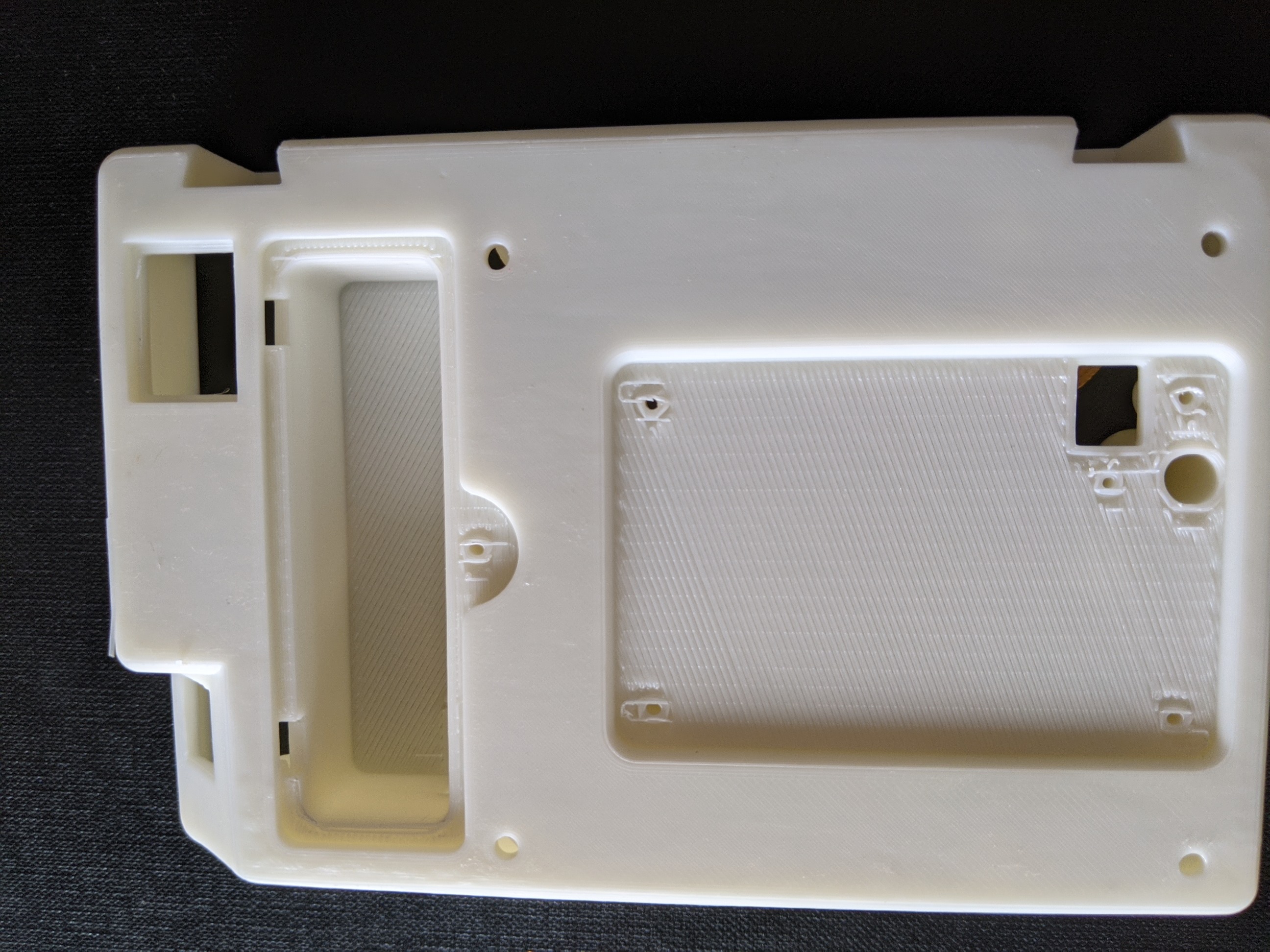
The results improved significantly. Thanks for your suggestions. I just wanted to know is there any localised setting to control the bridging. I want to keep the interface layers near the round holes as they tend to deform without the interface layers.
Thanks!
Experimenting with options
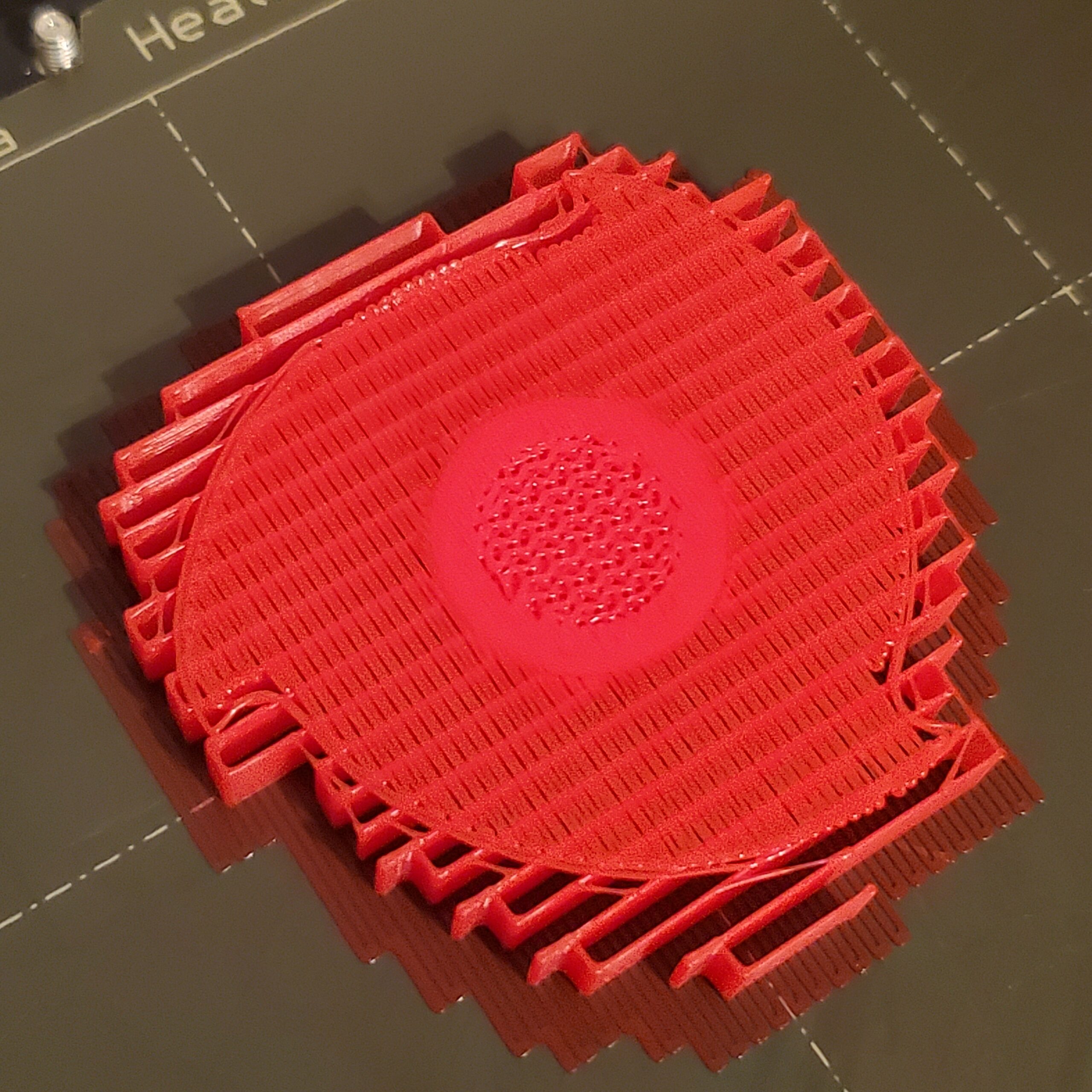
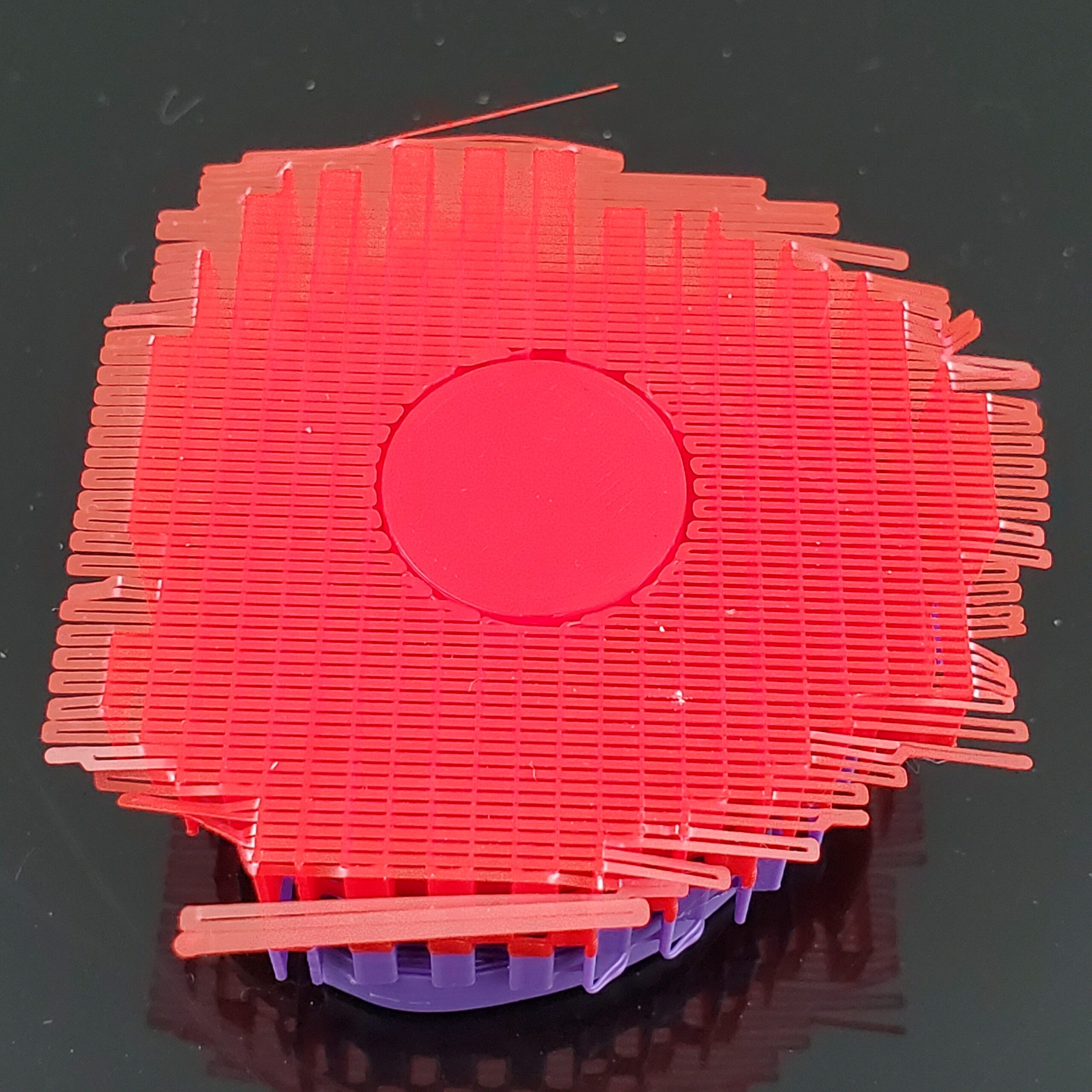
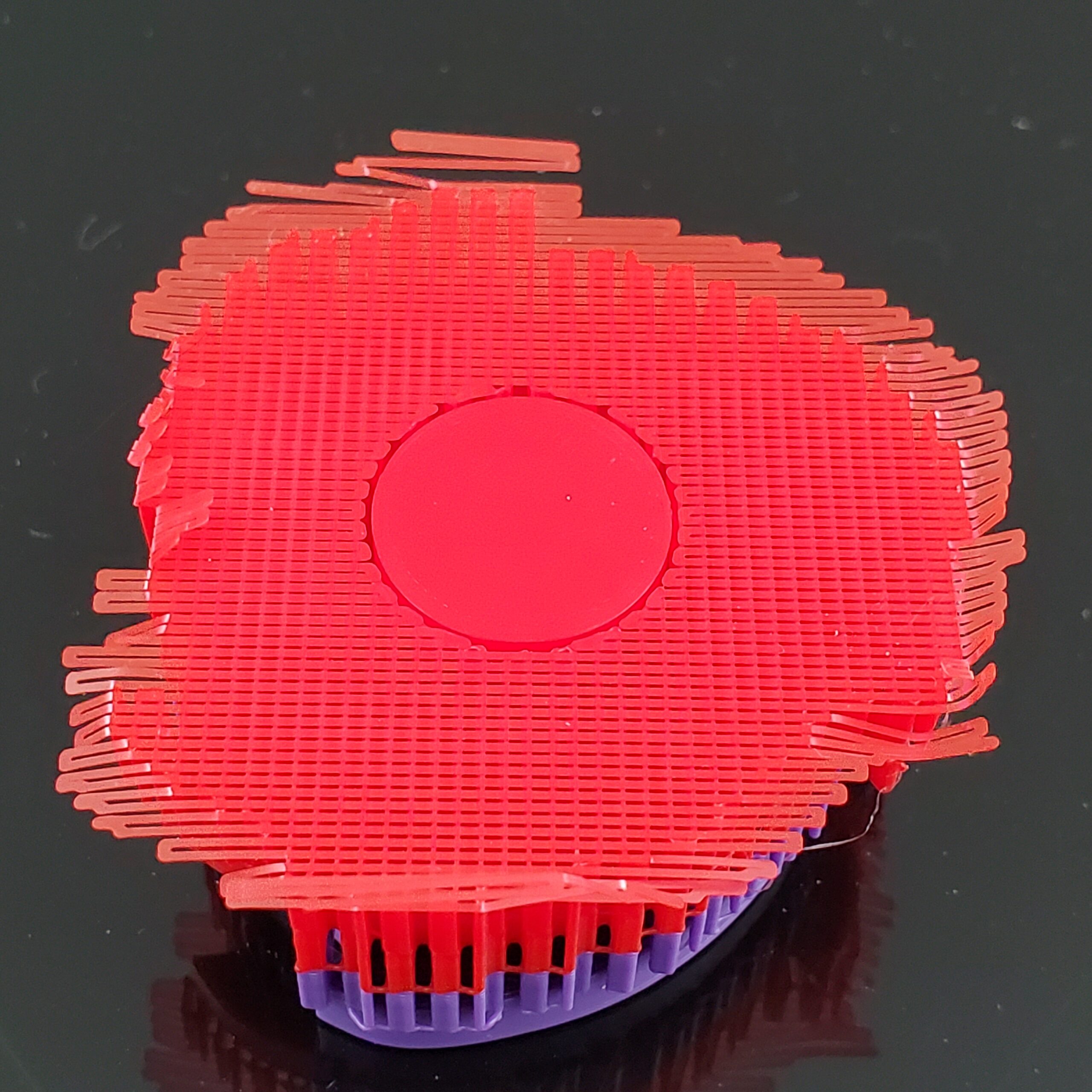
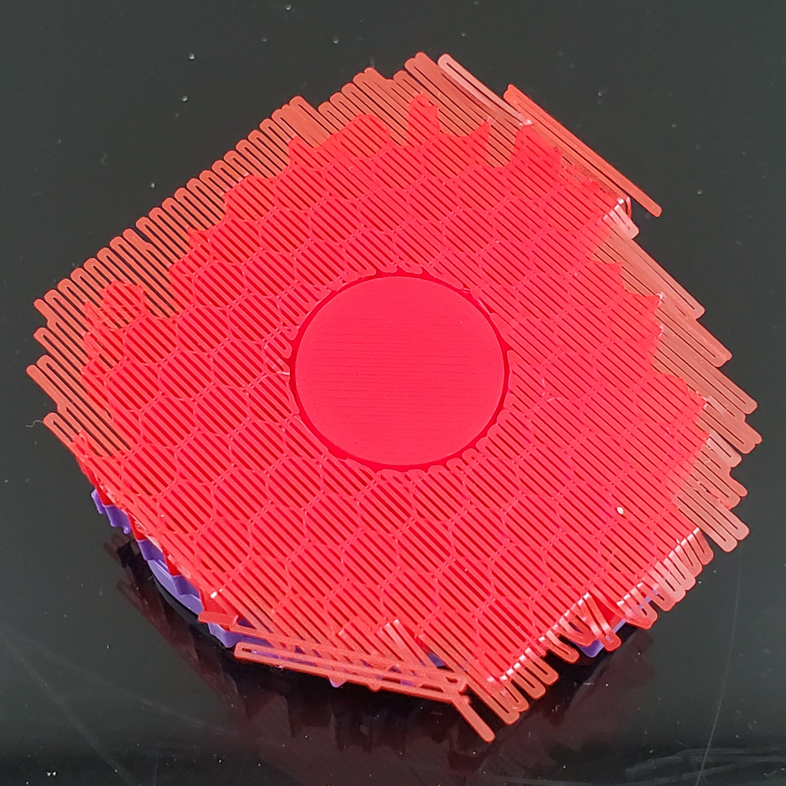
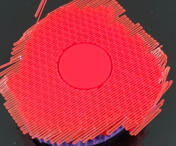
I ran across this thread while looking for ways I might improve the underside of a couple of parts I'm printing. They're for a model of a shredder, and are the shredding disks. When I first printed them using my usual support settings, the undersides were much uglier than I wanted, which is what prompted the search that landed me in this thread. I tried the suggestions "--" offered about eliminating the support interface and setting the gap to 0.01mm. Also made sure that the bridging was perpendicular to rectilinear supports. Figured I'd share my experiment and findings in case anyone else finds them useful.
First, the model I'm working on is one from that "other" site: https://www.thingiverse.com/thing:2473179.

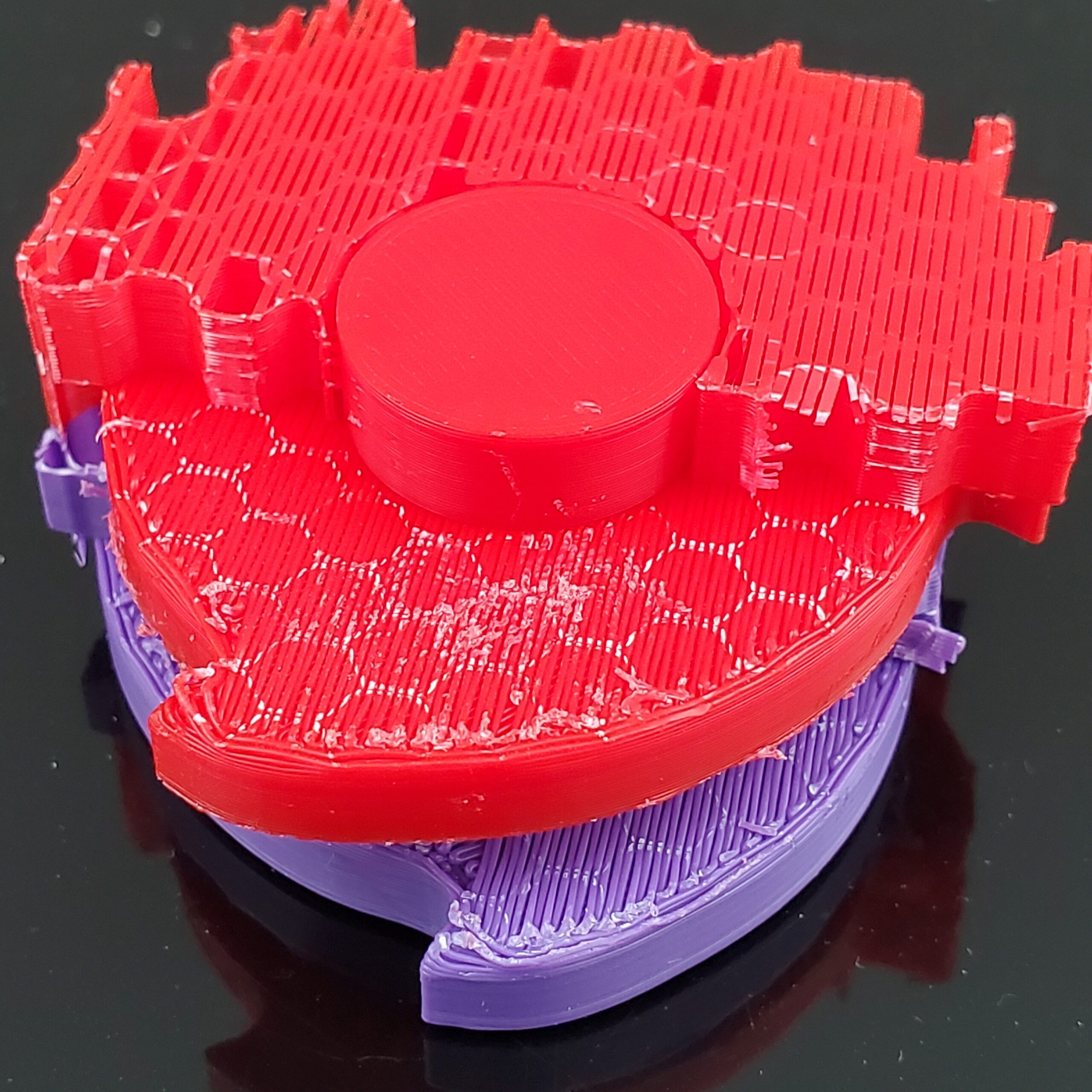
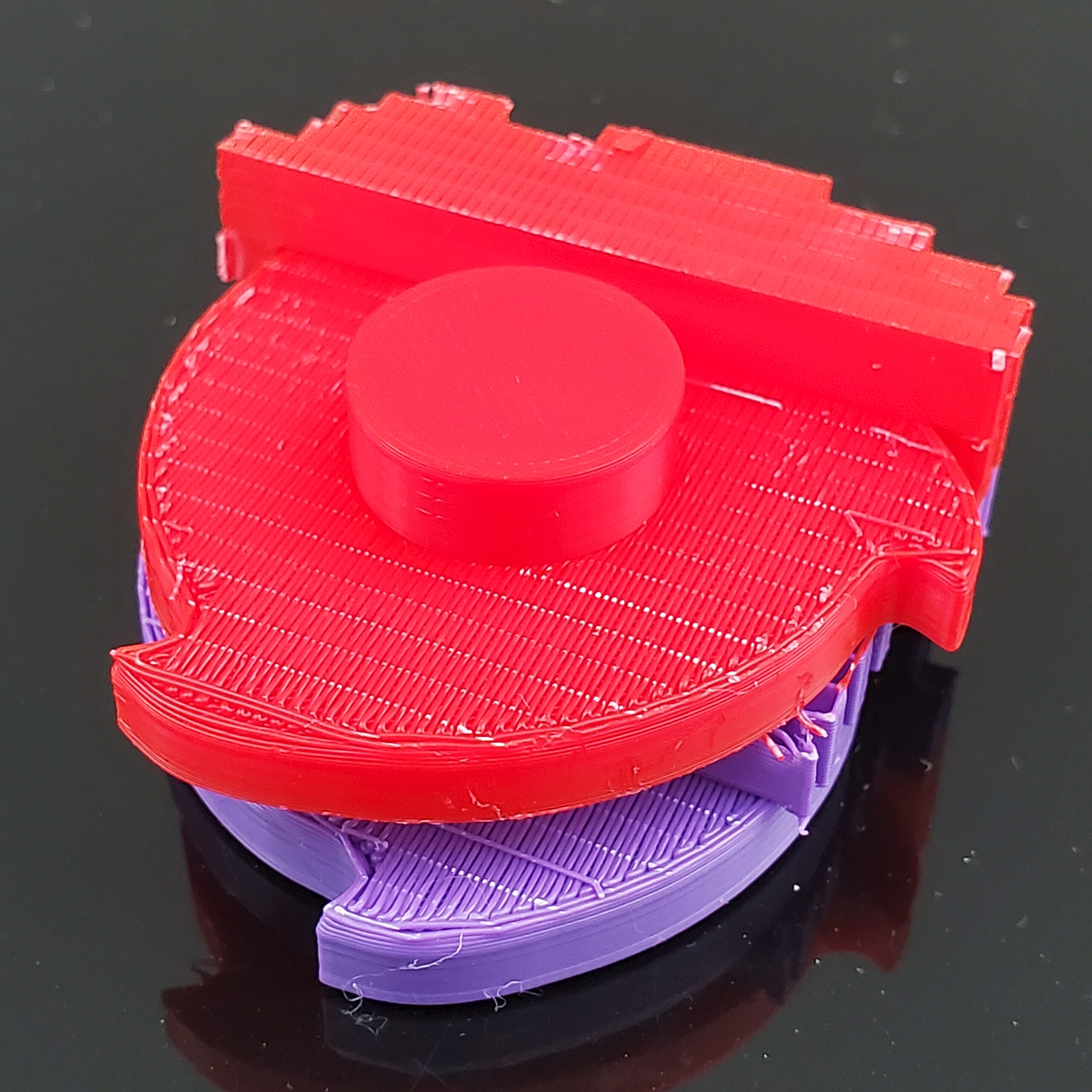
My first attempts at the driven shredding disk (red in the picture above, and I stuck with it) came out like this:
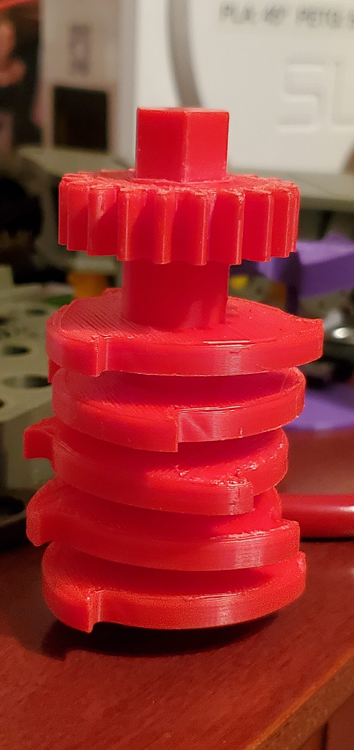
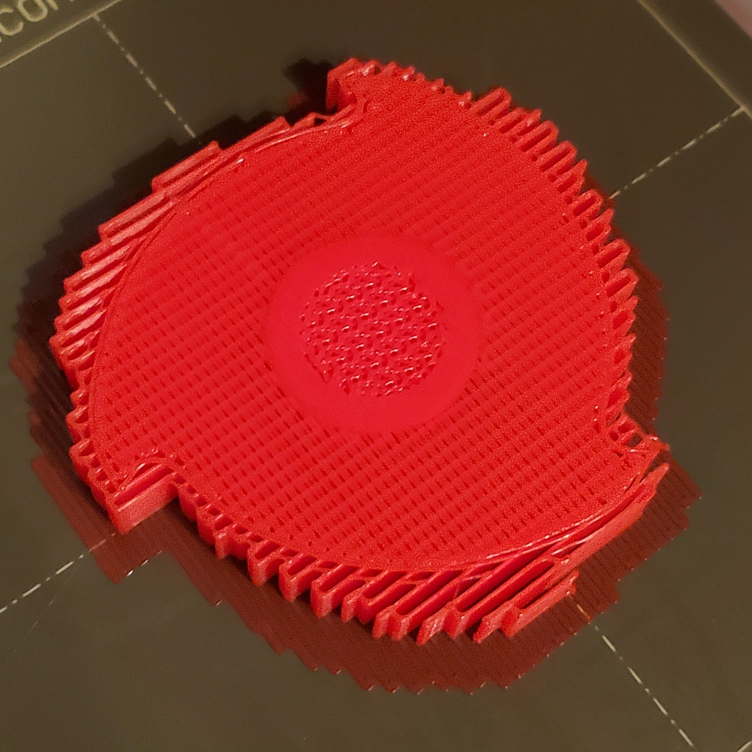
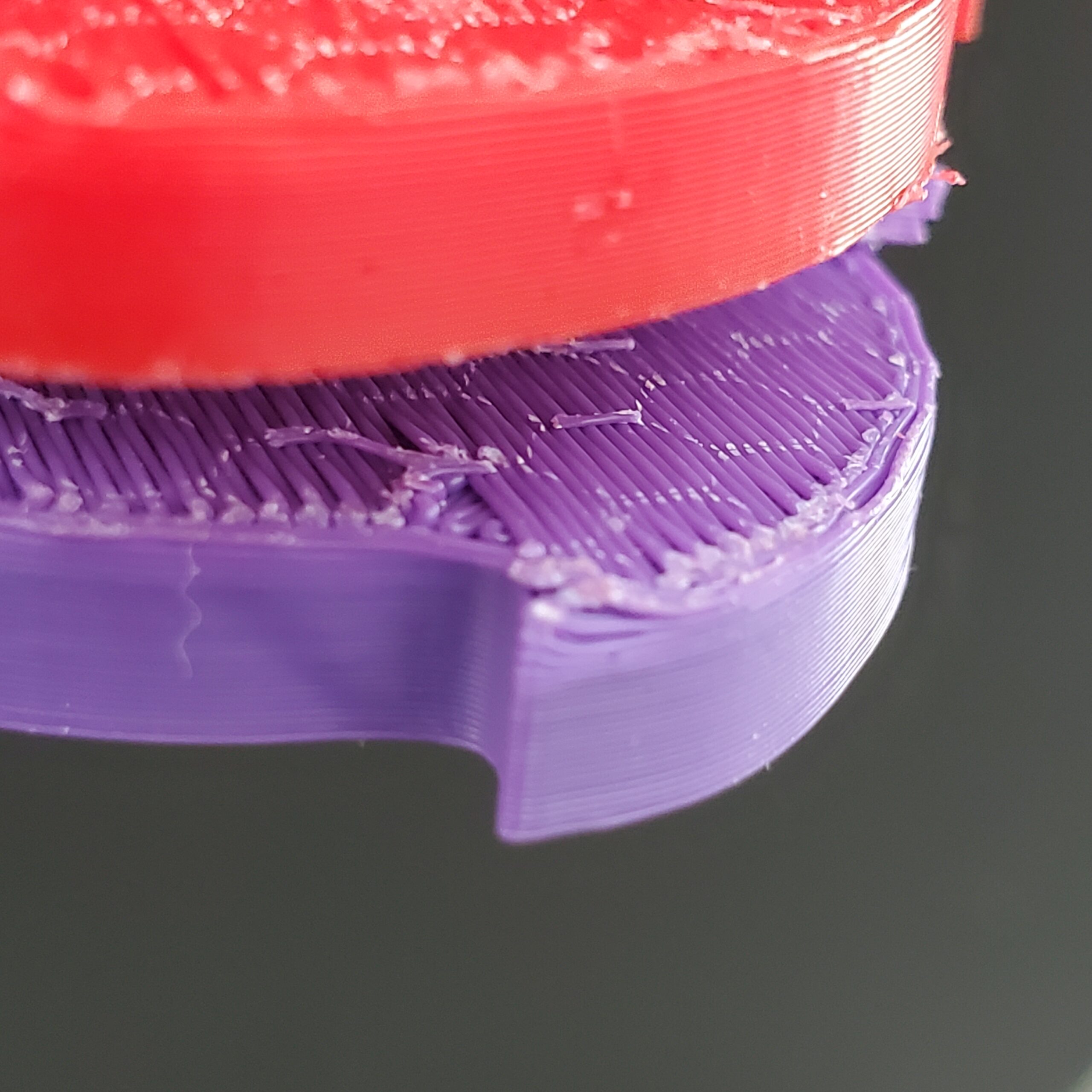
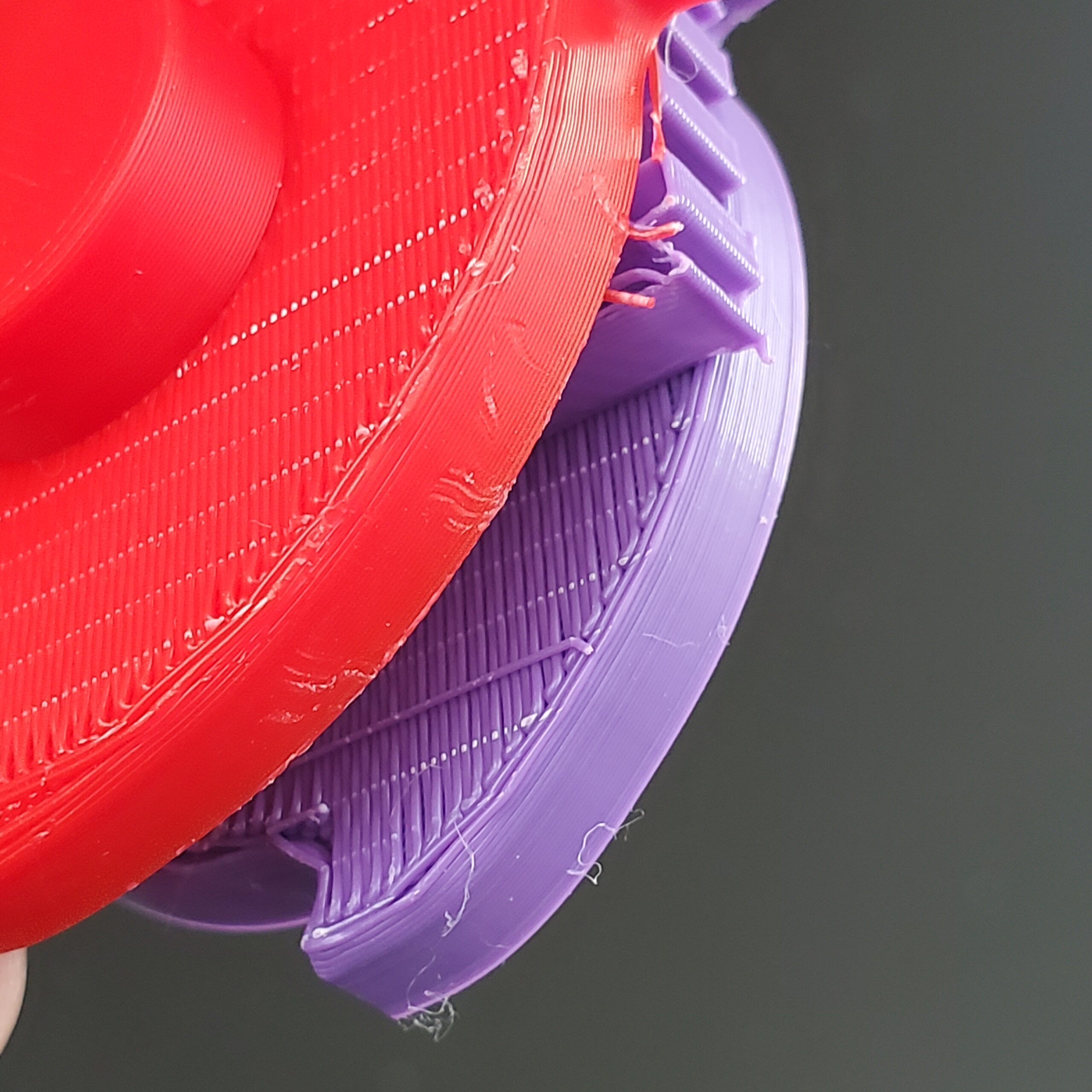
This is looking at the part from the bottom up. It's not bad, but you can see the underside of the horizontal toothed disk is not very clean. Here's a closer view from that part, as well as its neighbor:
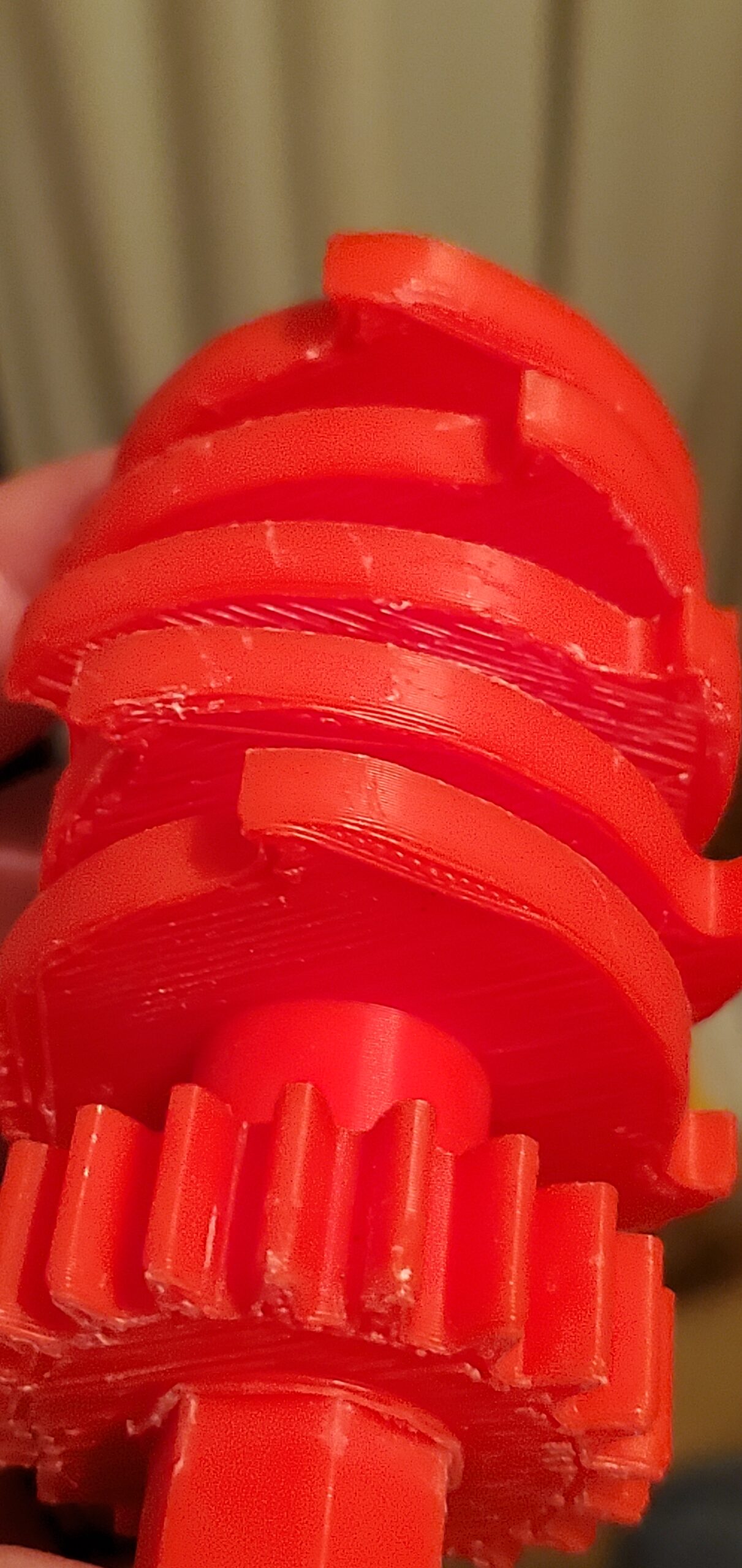
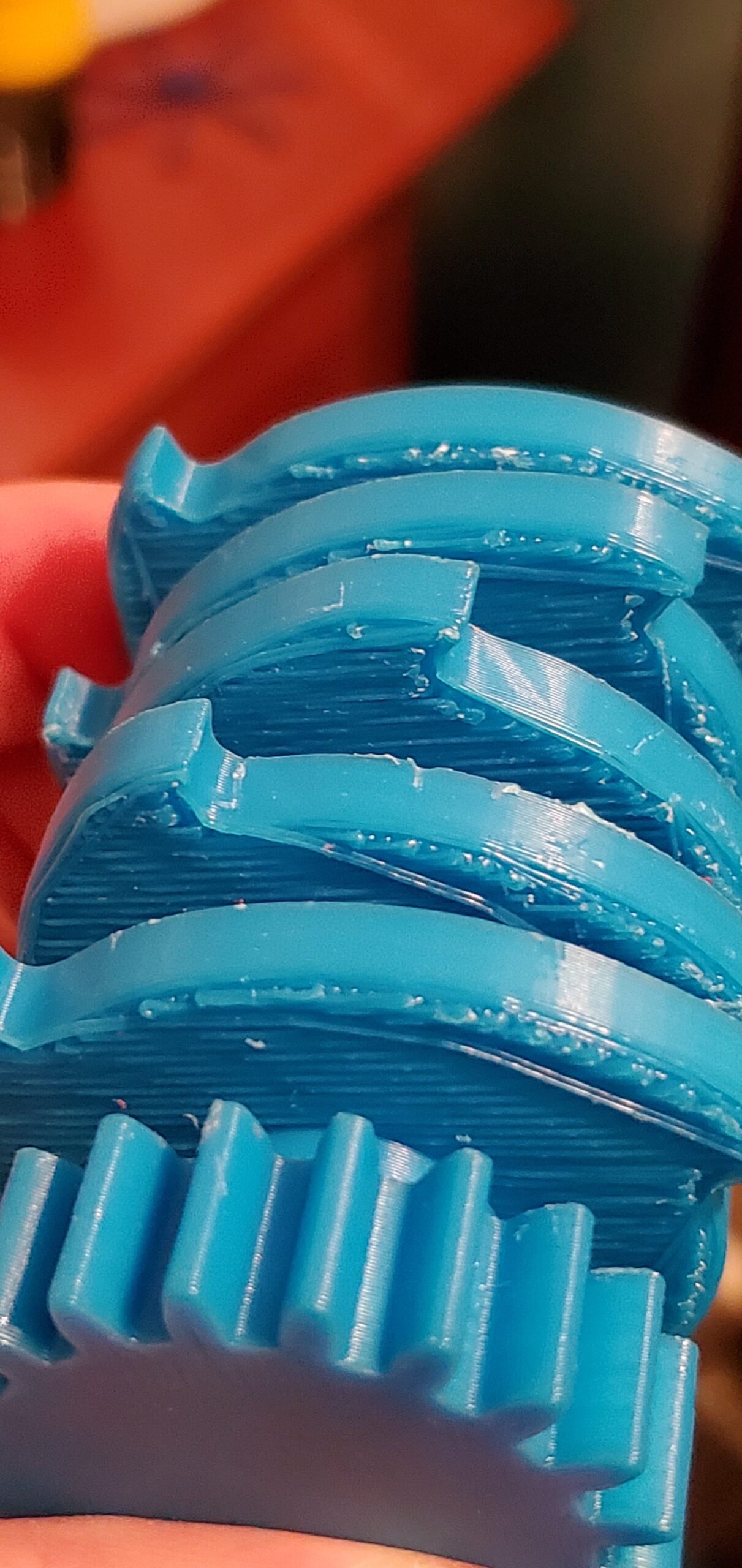
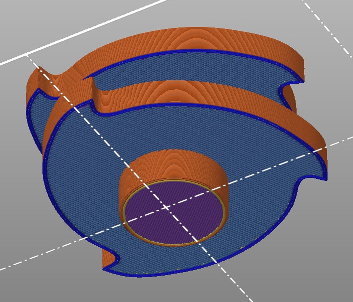
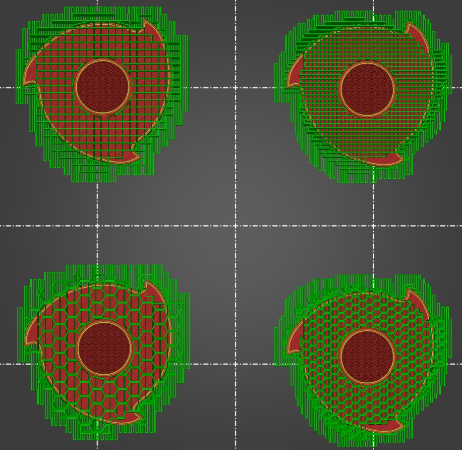
In addition to the general messy look of the bridged surface, it also looks like some perimeters got dragged in to the interior of the part (particularly noticeable in the blue one). So I started searching for ways to make it better, and that led me here. After reading the suggestions from "--" I wondered if the honeycomb support pattern might make a difference, and also whether a smaller spacing would help. That created four test cases - honeycomb vs. rectilinear, and 2mm vs 1mm spacing. I wanted to investigate the impact on the initial supports coming from the print surface and also those between the toothed disks, but didn't want to use filament wastefully, so I cut the part above the second disk for these tests. Here's a view from PrusaSlicer, looking up from below to show the overhanging perimeter and bridge infill areas:
All four test parts sliced, viewed from above cutaway between the two toothed disks:
And then we hit "Print" and we wait...
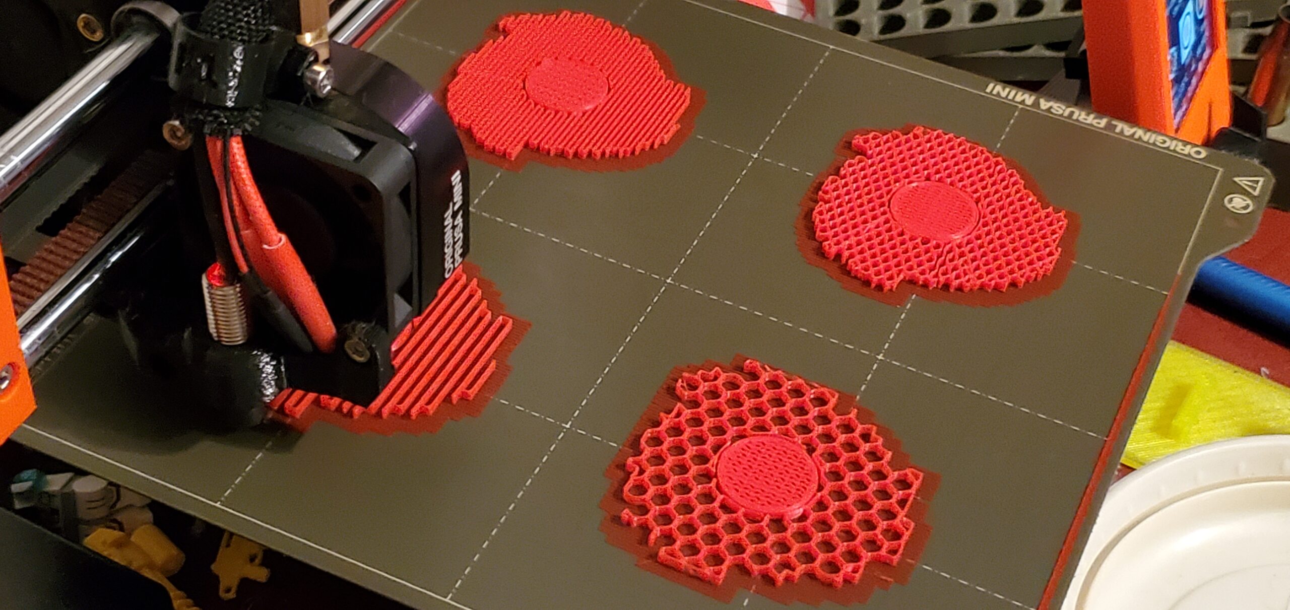
Took a series of shots after the first bridge layer went down, in case they showed anything useful:
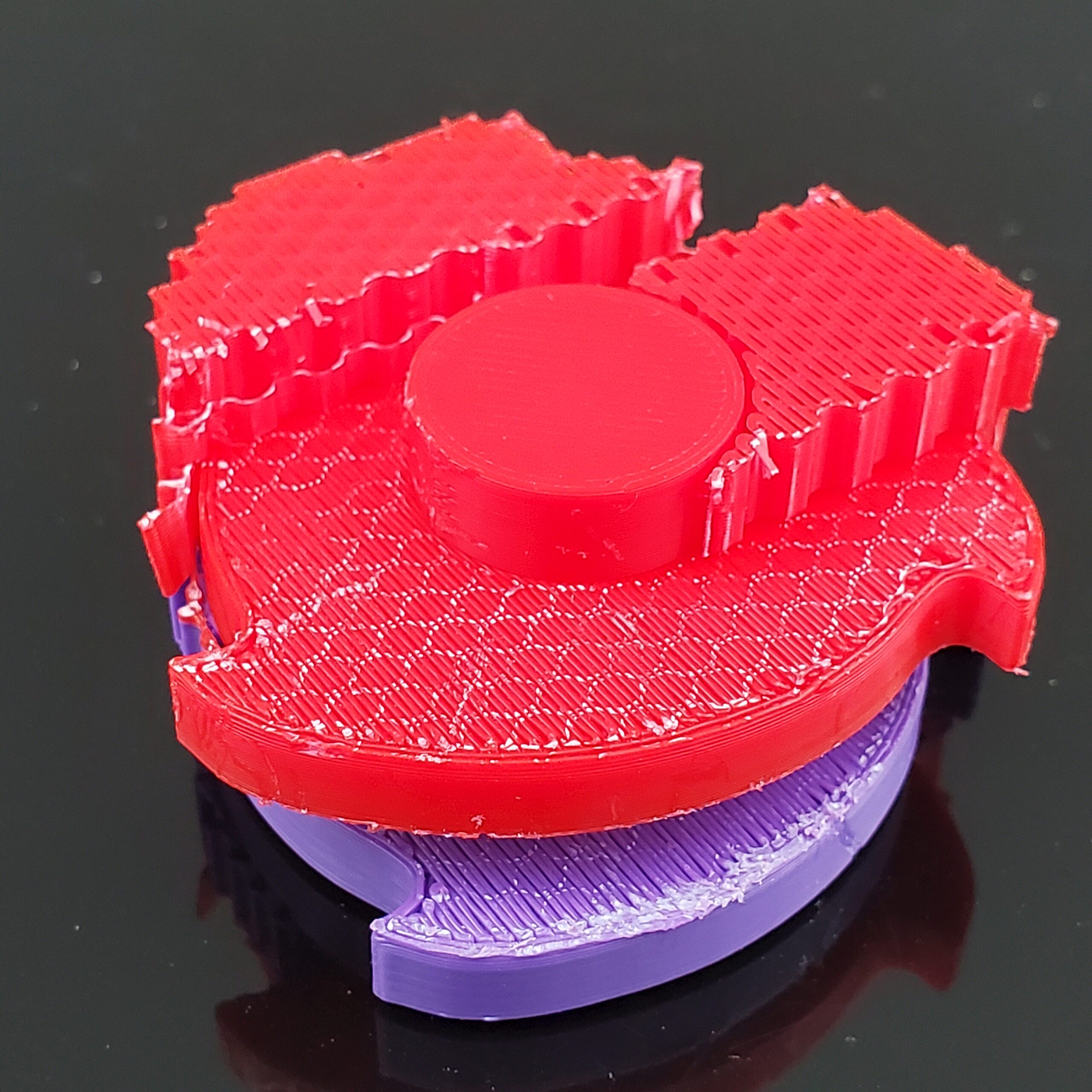
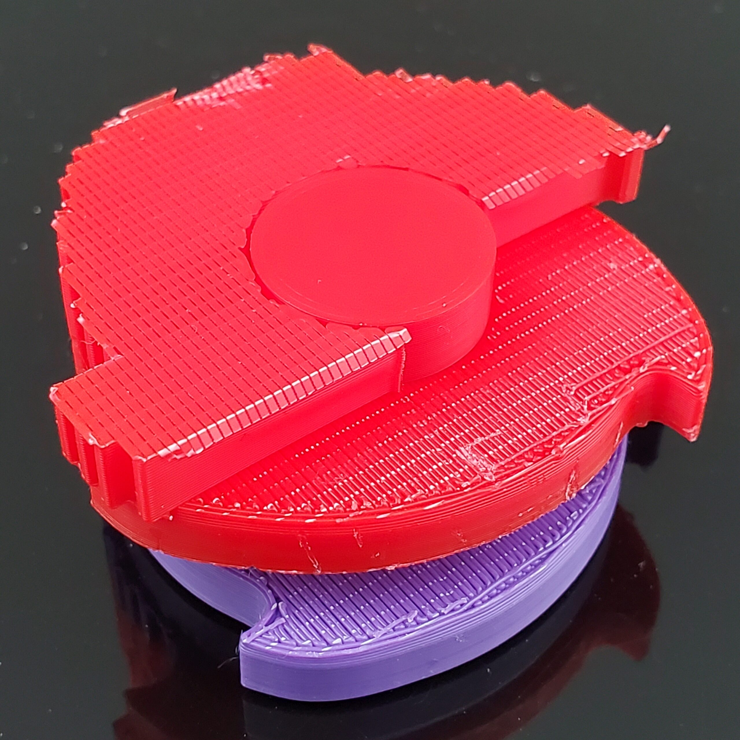
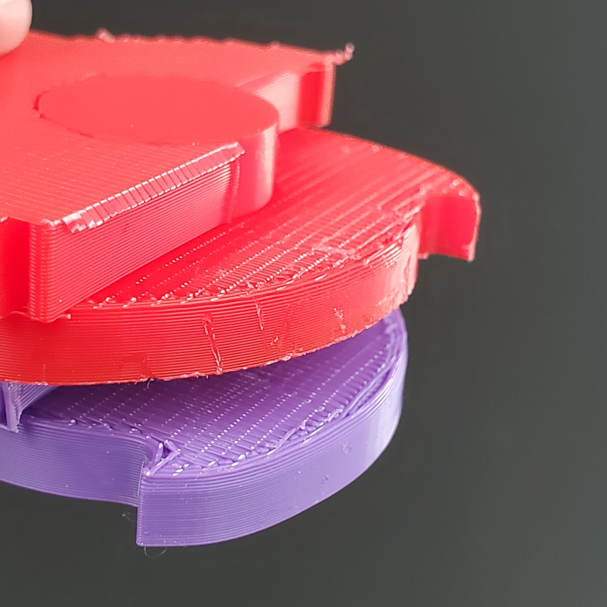
I failed to plan appropriately, and ran out of filament after the first toothed disk. But it worked out, because switching to purple allowed me to see the lines laid down right on top of the disk. Unfortunately, I forgot to take photos showing this, but here are each of the test pieces after they came off the printer. First, a view from the print bed side:
Then I got busy removing material. A few notes about what I observed during this process...
- The larger honeycomb was the most difficult to remove.
- The smaller honeycomb came off in convenient "chunks" that I had not expected
- Both rectilinear supports tended to "unravel" and come off in ribbons (typical in my experience)
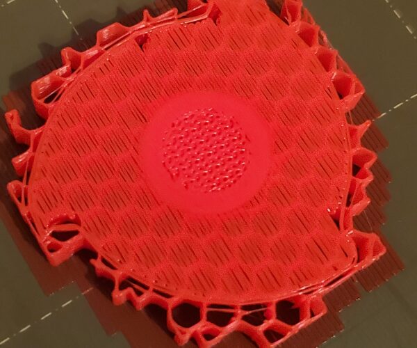
Then I took a closer look at each specimen. Let's start with the 2mm honeycomb:
As you can see in the left photo, there are fairly clear marks left on the undersides of both disks. Not a big concern for me, but worth noting. Also, and you can see this better in the right photo, there were issues with the overhanging perimeter at the tip of the tooth. This was not particularly surprising, as that happened to be over a void/"cell" in the honeycomb. But you can already tell that the general state of the underside is looking better.
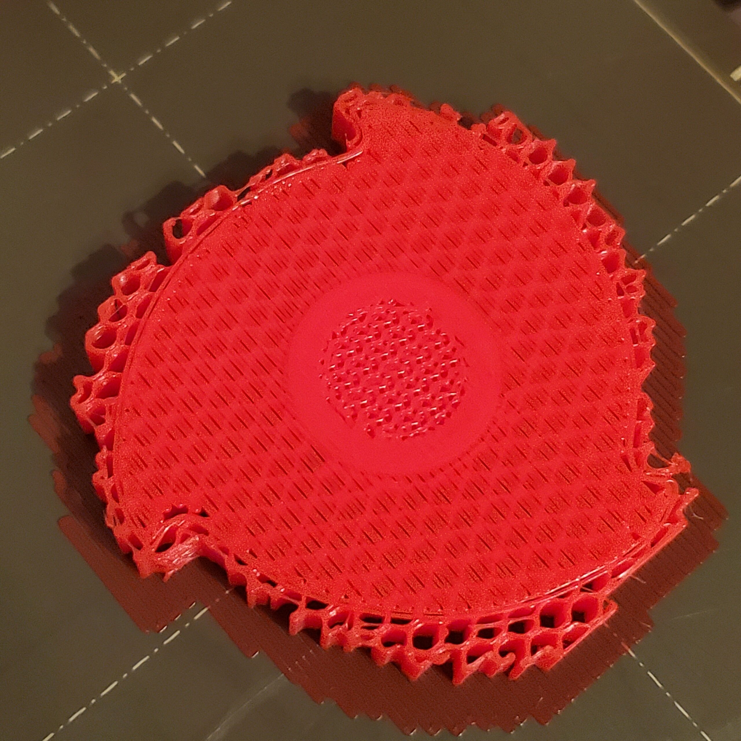
Moving on to the 1mm honeycomb:
First, notice the "chunk" behavior I mentioned earlier - I intended to leave all the support material on the back side of the central axle, but it came off readily with some of what I meant to remove. The markings on the underside of the disks is still pretty clear, but the issues with the overhanging perimeter appear to have been avoided using the smaller cell size. Nothing earth-shattering about that.
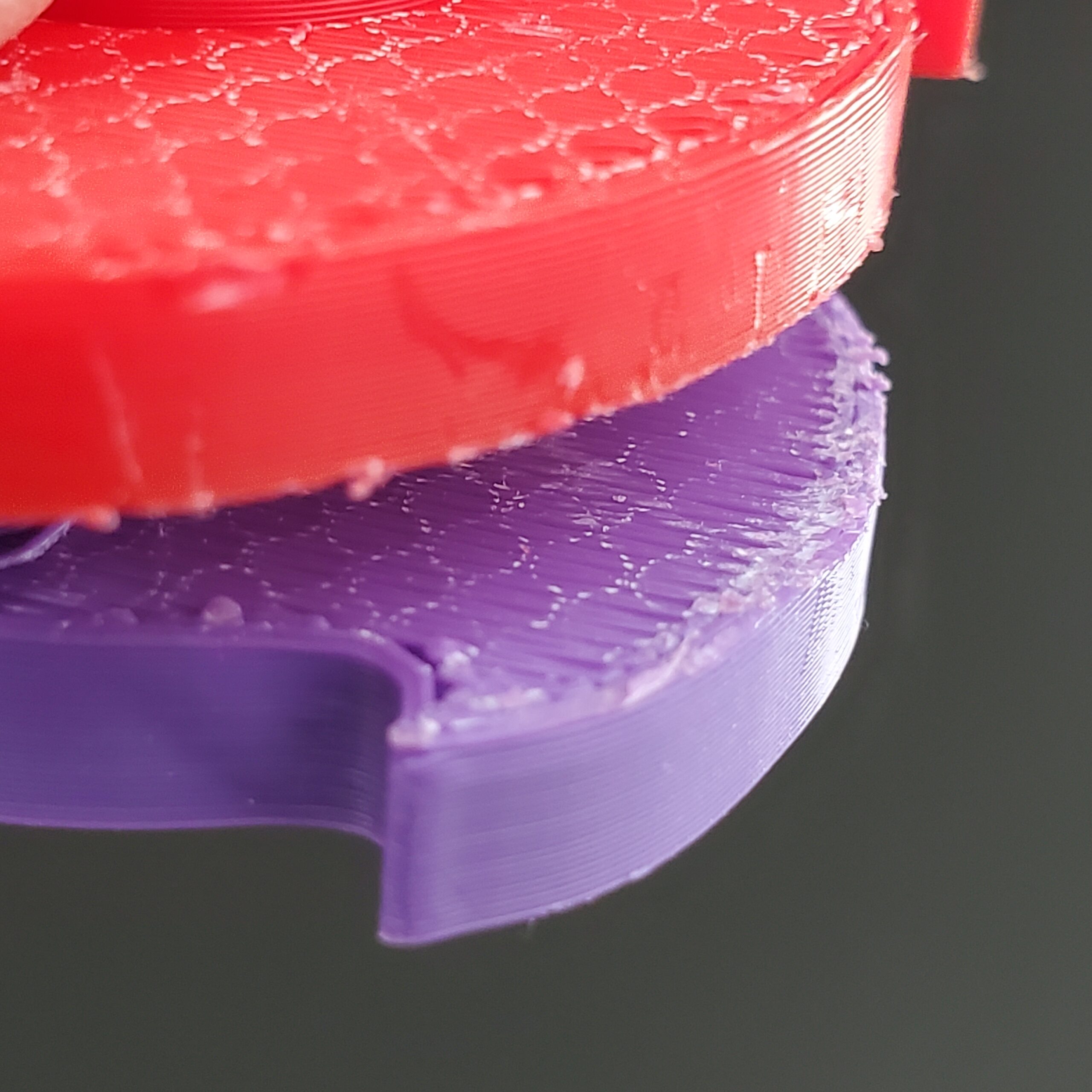
2mm rectilinear:
Markings left on the underside are less obvious, though they're still present. Similar issues with the overhanging perimeter on the tooth. I must say, I'm liking the way the underside surface is looking!
Finally, 1mm rectilinear:
You probably reached the same conclusion I did, but I'll go ahead and say it - this was the best I did. There are tool marks on the edge of the disk that are the result of my Neanderthal material removal technique, but both the perimeters and the bridged surfaces look pretty good here.
For posterity, the settings I used for this final test case were rectilinear supports, 1mm spacing, Z gap of 0.01mm, interface layers set to 0 (zero), "Don't support bridges" turned OFF, fan speed set to 50% for bridging (under filament settings in PrusaSlicer in case anyone doesn't know - I had to go searching for it).
If you found this experiment useful and have ideas for other experiments, please let me know. I really enjoy doing this kind of thing, and would be happy to do more of it.