90 degree transition weakest point - parts break all the time
Hello,
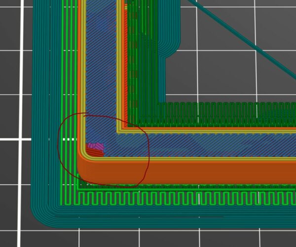
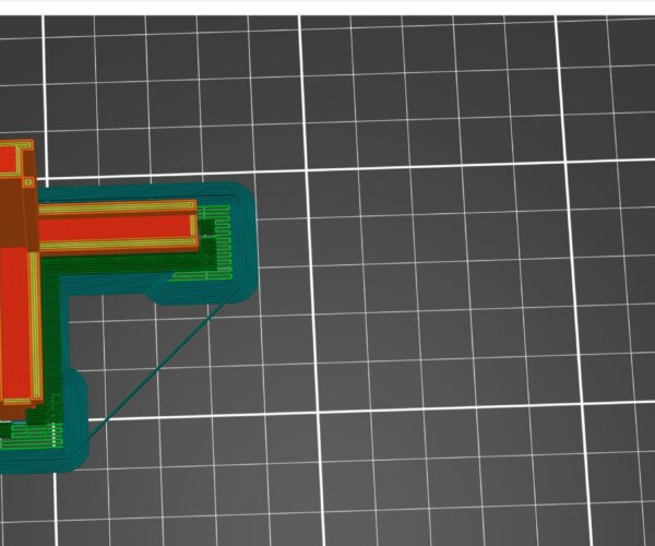
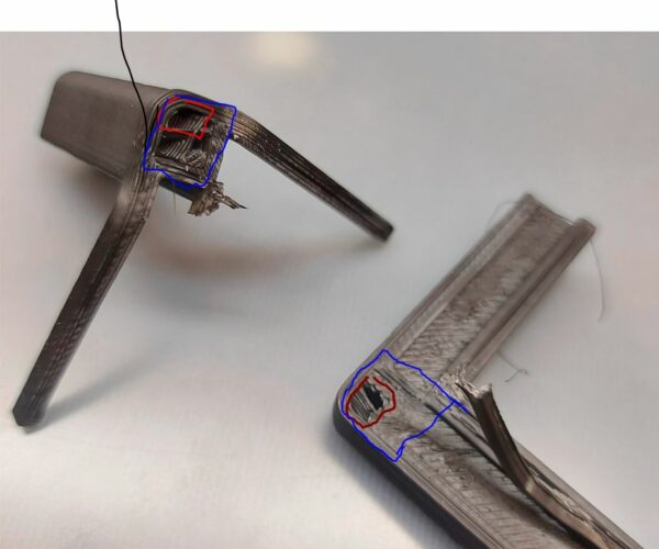
I'm new in printing but have had some success recently. What I failed on is the strength between same part sections with 90 degree transition from lower horizontal t0 vertical. Parts are breaking in the transition are at all time. ABS and PETG, same story. if anyone experienced that pls share what to tweak. I checked the slicing and I see that the cubic infill is almost covered fully by top layer of the horizontal part hence no transition of strength to vertical in that angle. Can I print it 100% strong across all plains with just a setting or a few changed in the prusa or I have to modify the design by adding an internal support box/rectangular that will get through bottom and to top parts. really appreciate any hint or advise. I'm sure this is a common learning curve:)
RE: 90 degree transition weakest point - parts break all the time
Hi!
If you are using PrusaSlicer, it is pretty easy to add a part modifier which can be used to strengthen key areas of your design.
Just import your file into PrusaSlicer. On the left pane it appears on the build plate. On the right, the file name appears under the heading "Name". to the right of "Name" is "Editing". Just right-click on the icon below "Editing" and a dialog appears. Choose "add modifier" and select a shape, like "Box". The shape will appear on the left pane, near your object. It also appears in the right pane, below the object. You can resize the modifier and move it to any part of the object.
Now here's the fun part... if you right-click the modifier in the right pane, you can change the infill and perimeters. If you were to say, make 4 perimeters, this would create a box within your object. If you increase the infill to 100%, that part of your object will be solid within the boundaries of the modifier. This is a good way to strengthen key point of your design without re-creating it.
¡no entiendo Español!
Nein! Nicht Versteh!
Я немного говорю по-руÑÑки но не очень хорошо, и...
I'm not very good at English either! Maybe someday I'll find a language I'm good at?
RE: 90 degree transition weakest point - parts break all the time
What chicago-Keri suggested makes sense. You may also want to post your project here for additional design supports. Save your project from Prusaslicer's File menu as a 3mf file. Zip compress it (or the forum software won't accept it), then attach it to a post here. I've gotten some amazing help here from folks who have forgotten more about 3D Design optimization than I'll ever know.
Formerly known on this forum as @fuchsr -- https://foxrun3d.com/
RE: 90 degree transition weakest point - parts break all the time
Using a modifier is one way to do it. You can also do it at model creation time in your CAD software. You can model in small voids in the internal spaces of your models. Prusa Slicer (or any slicer really) will then surround the voids with perimeters. This gives you extra plastic and so strengthens the part. The advantage of doing it in your CAD is that its not then slicer dependent and you dont have to manually position modifiers each time.
There's an old thread or 2 around here describing the same problems and the solutions but of course the search function sucks.
RE: 90 degree transition weakest point - parts break all the time
Take a scrap part and try to snap it. If it was printed horizontally it will be much tougher than one printed vertically. The molecules are aligned by the extrusion process and very little crosses the layer boundaries.
If a part needs the strength in three dimensions then it can pay to rotate it through 45 degrees so that some of the lay vectors into each dimension.
Cheerio,
RE: 90 degree transition weakest point - parts break all the time
Thanks, I had this in mind and played with different angles in slicer. yes it will improve the strength and will increase support requirement. cheers
RE: 90 degree transition weakest point - parts break all the time
it is possible to increase the strength that way. I will extend the walls which will connect ends of the columns, like triangles. more printing though. thanks
RE: 90 degree transition weakest point - parts break all the time
yeah. did you mean insert the support box or integrate box as an internal part in this area between low part and vertical one? My issue is that slicer and printer use bridge infill incorrectly, my opinion.
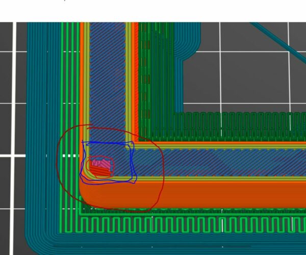
the first layer that covers horizontal part leaves very little to link up two infills in lower and and upper parts and that is the weakest area.
slicer shall somehow continue building a vertical hollow/infilled column not just sticking it on the top of almost completed layer. It comes down to the red square in the image needs to be to the size of the expected blue one. How to prevent blue bridging layer to stop closing the void for the infill?
RE: 90 degree transition weakest point - parts break all the time
It is easy enough to see without actually printing.
When you press the "Slice" button, the build plate switches to Preview mode. This shows all of the layers as the part is built up. The vertical slider to the right of the preview window allows you to view specific layers as the part will be extruded. I suggest doing this with your original part, and re-slice after every modification to see the result. This saves a lot of time and filament.
This picture shows a giant 3Dbenchy with a 25mm cube modifier forcing an otherwise 20% Gyroid infill to 100% Rectilinear infill. The upper slider to the right of the preview window is set to 23.4mm height, at layer 117. Notice that the modifier does not extend beyond the boundaries of the original Benchy. To cause the modifier to extend beyond the part, choose "Add Part" instead of "Add Modifier".
Good luck!
¡no entiendo Español!
Nein! Nicht Versteh!
Я немного говорю по-руÑÑки но не очень хорошо, и...
I'm not very good at English either! Maybe someday I'll find a language I'm good at?


