Visual cues for nozzle alignment and height during Preflight Check?
Hello,
Short of using the Nyloc mod, I've tried my best to level my bed as described in the assembly instructions and still end up with, more or less, an uneven print bed near the middle and the lower right corner.
As I run through the Preflight checklist, I can't clearly see from the guide where the nozzle is supposed to land on the print bed when looking at it from top down or from either side. Here is what I see:
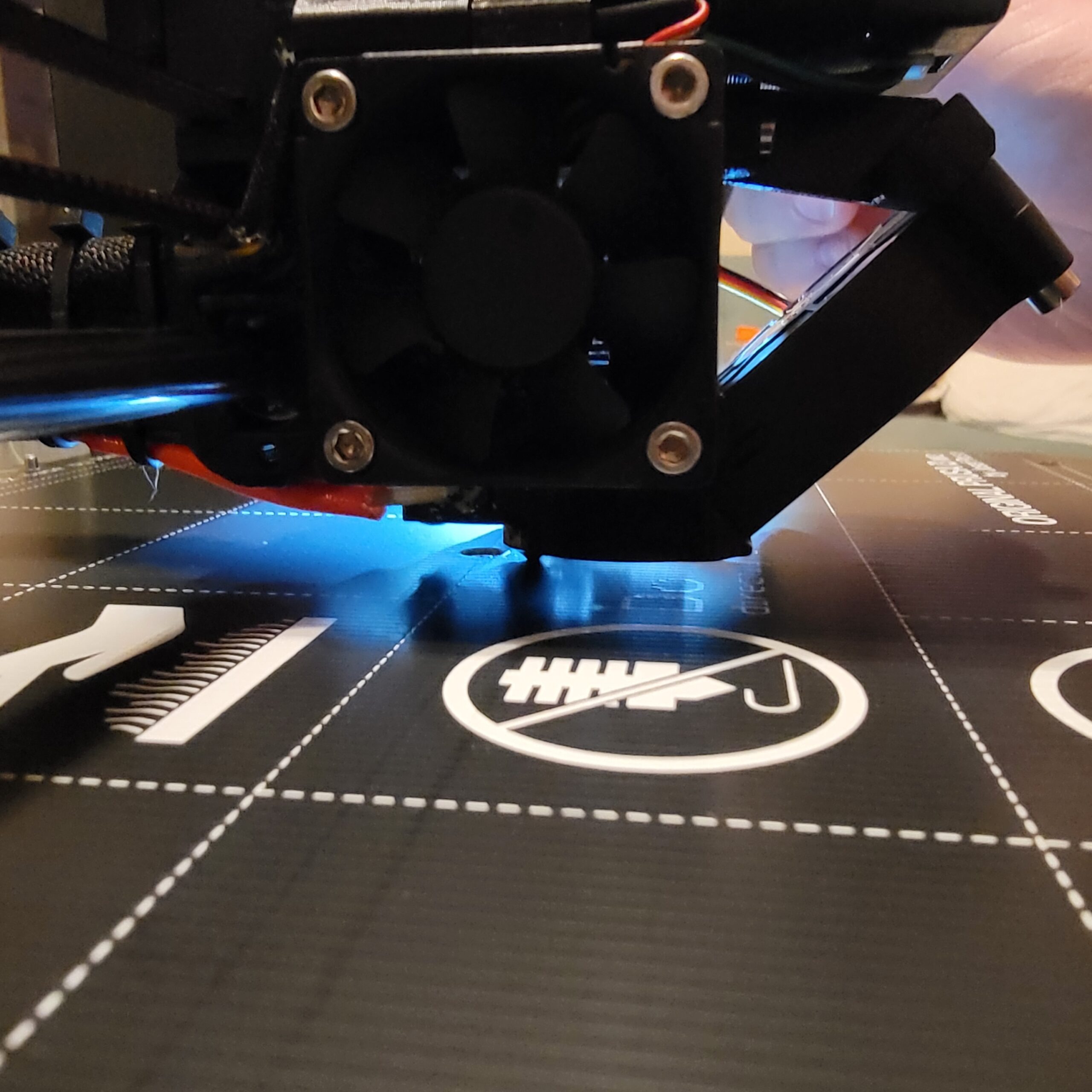
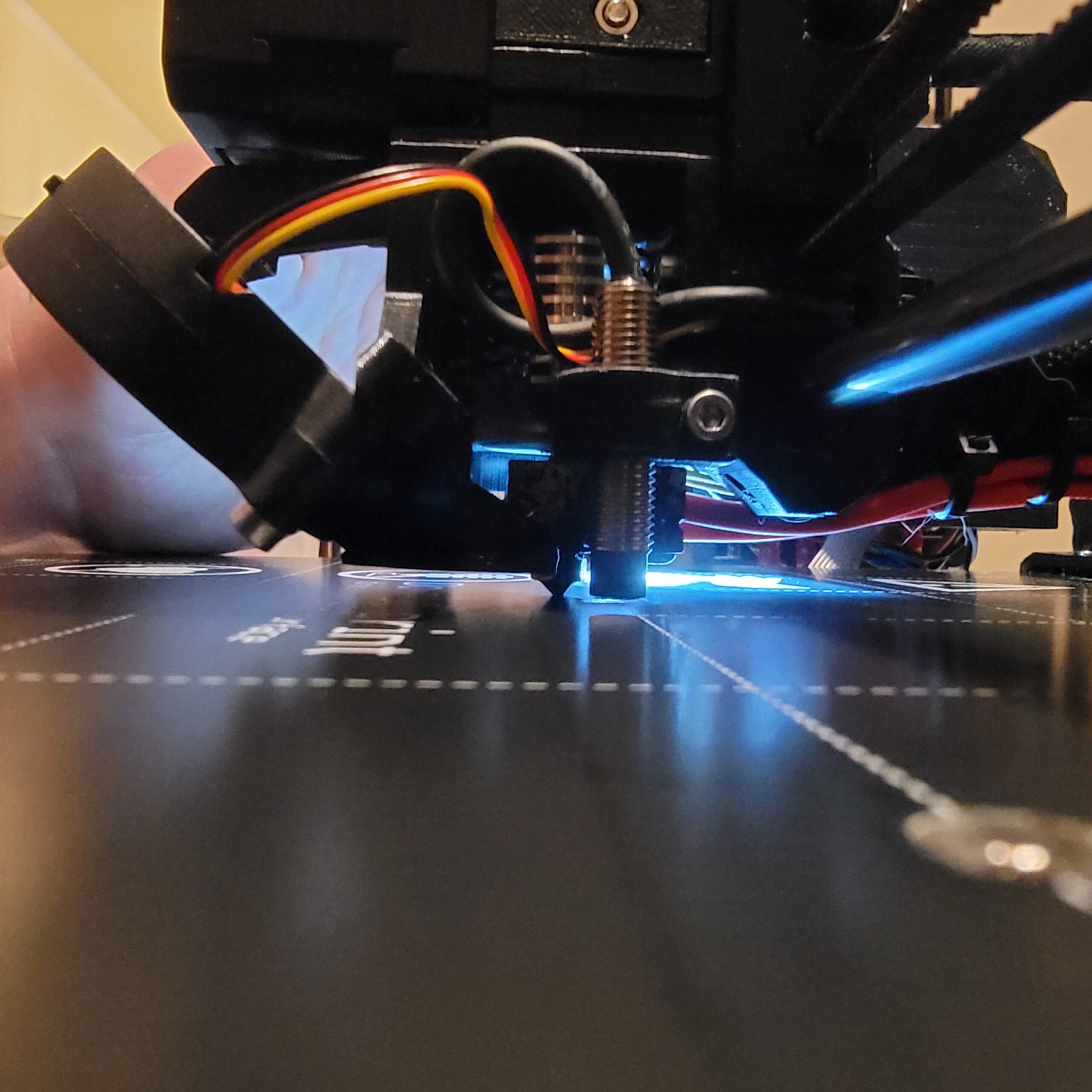

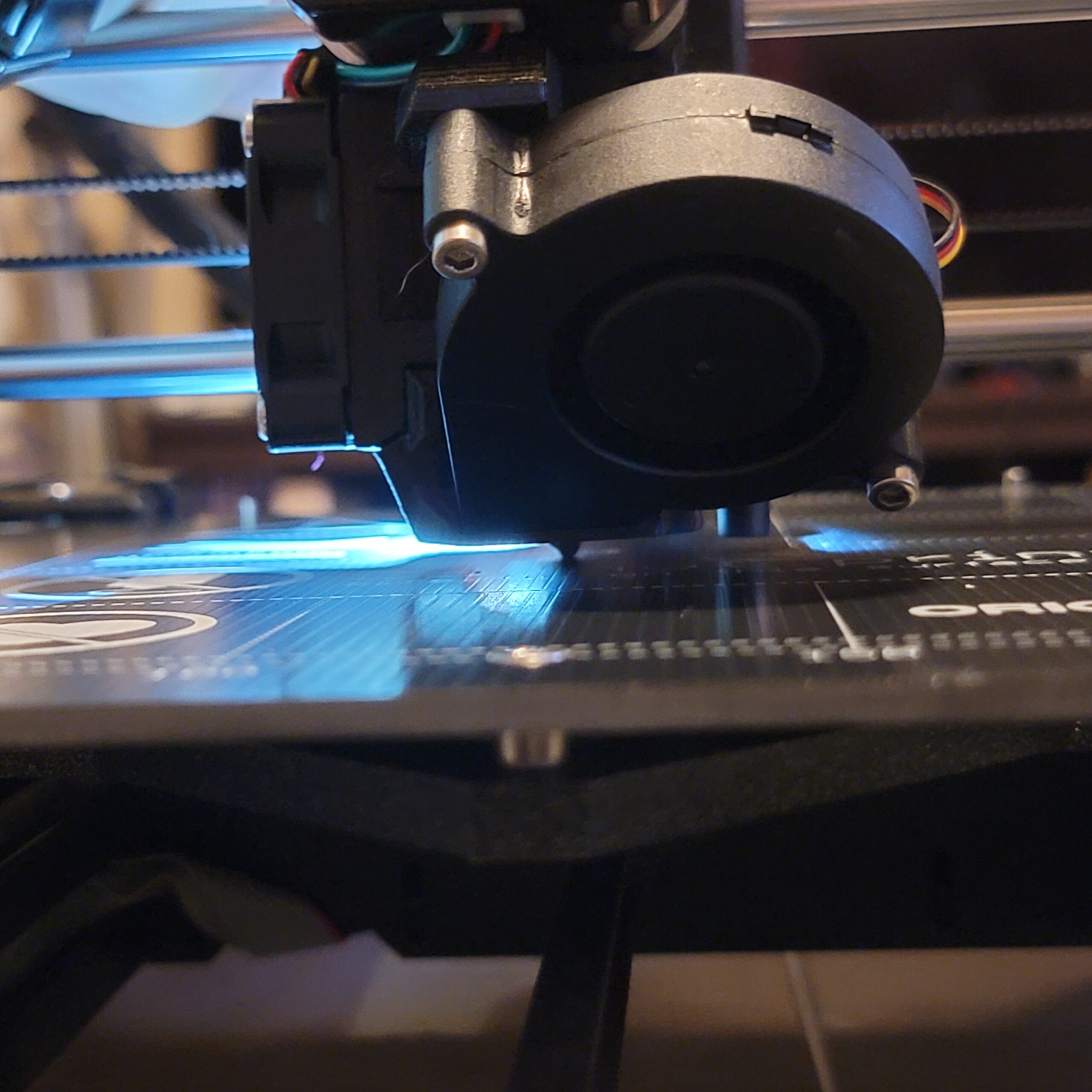
I've been putting it just below the center screw (X ~= 125, Y ~=103?), using this Super PINDA tool to adjust the height, and then following the method below to adjust the height of the nozzle, but it feels like my live Z adjust ends up being too low (~1200-~1300) and ends up still slightly scratching my print bed or cutting it close:
-
Using the threaded rods, lower the extruder and position the nozzle close to where my pictures display (~103)
-
Raise the extruder using both threaded rods simultaneously with a very slight turn, hardly any force, to avoid scratching the print bed
-
Move the extruder all the way to the left as far as it will go
-
Place a piece of paper under the extruder
-
Manually rotate both threaded rods until the nozzle pins the paper to the bed and I cannot remove the paper
- If the bed bends, I back off slightly, then gently rotate until the nozzle makes contact again, making just the faintest tap to indicate it connects
-
Turn the left threaded rod to raise the extruder up and stop when I can slide the paper out
-
While keeping the paper under the path of the extruder, slowly move the extruder to the right side.
- If the nozzle catches the paper and starts to drag it:
- Move the extruder slightly back to the left, just barely away from that spot
- Raise the right threaded rod only
- Try to move the extruder to the right again so that it doesn't catch and drag the paper at he same spot
- Repeat until I reach the right side
- If the nozzle catches the paper and starts to drag it:
-
Once the extruder is enough to the right that I can lower the nozzle to the very edge of the print bed, make sure that the sheet of paper is under the nozzle
-
Lower the extruder using the right threaded rod only until the nozzle pins the paper to the bed and I cannot remove the paper.
-
Turn the right threaded rod to raise the extruder up and stop when I can slide the paper out.
-
While keeping the paper under the path of the extruder, slowly move the extruder to the left side:
- If the nozzle catches the paper and starts to drag it:
- Move the extruder slightly back to the right, just barely away from that spot
- Raise the left threaded rod only
- Try to move the extruder to the left again so that it doesn't catch and drag the paper at the same spot
- Repeat until I reach the left side
-
Repeat these steps, moving the extruder from left to right and right to left, until it never catches and drags the paper
-
Move it back to the center of the print bed as before (Y ~= 103)
-
Adjust the Super PINDA height using the Super PINDA tool to adjust the height of the PINDA
Am I performing the preflight check beginning at the right spot, and is this a reliable way to perform the preflight check using the paper method described?
Best Answer by Neophyl:
Thats what the pinda sensor is for when in actual use. You just need it set up enough to be in working range.
When you do a mesh bed level (which unless you change the start routine it does before every print) then it will probe the steel print surface and adjust the first layer. In the lcd menu once your printer is set up and calibrated you can change probing from 3x3 to 7x7 to get a denser map. You dont need a perfectly level bed which is why the mk3 uses fixed spacers. While getting as close to level is ideal its not 'necessary'. You are just getting into general range so that the nozzle doesnt plow into the bed by having the pinda too far away outside its detection envelope.
What are you trying to actually achieve when you say "very small, precise distance measurements between extruder elements and the print bed" ?
You can adjust things afterwards using the live z. For example the printer will home and stop at whatever height the pinda detects the steel sheet. If I wanted my nozzle to be 0.3mm away when it stops I would then dial the Live Z and using a 0.3mm reference gauge (feeler gauge) would adjust until the gauge just fit. Once that was done you would know that Live Z value of -x.xxx = 0.3mm away from the print surface. Naturally you are limited by the pinda's max detection range of 2mm. Personally I wouldn't go too close to the max of -2.000 just for repeatability/reliability sake. Also please remember that the probe is temperature dependent so in actual use its always best to preheat your bed and soak heat it before starting a print.
For normal printing we don't worry too much about the actual first layers thickness, we adjust more on if the print extrusion lines are squished together enough to give an unbroken first layer. But it sounds like you have something different in mind which is why the questions.
RE: Visual cues for nozzle alignment and height during Preflight Check?
All you are trying to achieve is that the nozzle height is just touching the bed (at the highest spot really which is why you move it about) so that the pinda when set is close to the correct height relative to the nozzle. And a Live Z setting of -1200 to -1300 is quite normal and not 'too much'. The probe should be reliable up to 2mm away (-2000) so that's near the middle of the range.
RE:
All you are trying to achieve is that the nozzle height is just touching the bed (at the highest spot really which is why you move it about) so that the pinda when set is close to the correct height relative to the nozzle. And a Live Z setting of -1200 to -1300 is quite normal and not 'too much'. The probe should be reliable up to 2mm away (-2000) so that's near the middle of the range.
When you refer to the "highest spot", if my bed is not evenly leveled, should I try to perform this step closer to where the bed is more elevated? There always seems to be more risk of scratching my print bed in the lower right quadrant, so should I try to perform the preflight check and the Super PINDA height down there where it's at the greatest risk of catching the bed?
Also, if I want to get very small, precise distance measurements between extruder elements and the print bed (e.g. 2mm between extruder and print bed), is there a tool I can use for that, or is it just a matter of finding something of similar dimensions and using it as a reference?
RE: Visual cues for nozzle alignment and height during Preflight Check?
Thats what the pinda sensor is for when in actual use. You just need it set up enough to be in working range.
When you do a mesh bed level (which unless you change the start routine it does before every print) then it will probe the steel print surface and adjust the first layer. In the lcd menu once your printer is set up and calibrated you can change probing from 3x3 to 7x7 to get a denser map. You dont need a perfectly level bed which is why the mk3 uses fixed spacers. While getting as close to level is ideal its not 'necessary'. You are just getting into general range so that the nozzle doesnt plow into the bed by having the pinda too far away outside its detection envelope.
What are you trying to actually achieve when you say "very small, precise distance measurements between extruder elements and the print bed" ?
You can adjust things afterwards using the live z. For example the printer will home and stop at whatever height the pinda detects the steel sheet. If I wanted my nozzle to be 0.3mm away when it stops I would then dial the Live Z and using a 0.3mm reference gauge (feeler gauge) would adjust until the gauge just fit. Once that was done you would know that Live Z value of -x.xxx = 0.3mm away from the print surface. Naturally you are limited by the pinda's max detection range of 2mm. Personally I wouldn't go too close to the max of -2.000 just for repeatability/reliability sake. Also please remember that the probe is temperature dependent so in actual use its always best to preheat your bed and soak heat it before starting a print.
For normal printing we don't worry too much about the actual first layers thickness, we adjust more on if the print extrusion lines are squished together enough to give an unbroken first layer. But it sounds like you have something different in mind which is why the questions.
RE: Visual cues for nozzle alignment and height during Preflight Check?
Thats what the pinda sensor is for when in actual use. You just need it set up enough to be in working range.
When you do a mesh bed level (which unless you change the start routine it does before every print) then it will probe the steel print surface and adjust the first layer. In the lcd menu once your printer is set up and calibrated you can change probing from 3x3 to 7x7 to get a denser map. You dont need a perfectly level bed which is why the mk3 uses fixed spacers. While getting as close to level is ideal its not 'necessary'. You are just getting into general range so that the nozzle doesnt plow into the bed by having the pinda too far away outside its detection envelope.
What are you trying to actually achieve when you say "very small, precise distance measurements between extruder elements and the print bed" ?
You can adjust things afterwards using the live z. For example the printer will home and stop at whatever height the pinda detects the steel sheet. If I wanted my nozzle to be 0.3mm away when it stops I would then dial the Live Z and using a 0.3mm reference gauge (feeler gauge) would adjust until the gauge just fit. Once that was done you would know that Live Z value of -x.xxx = 0.3mm away from the print surface. Naturally you are limited by the pinda's max detection range of 2mm. Personally I wouldn't go too close to the max of -2.000 just for repeatability/reliability sake. Also please remember that the probe is temperature dependent so in actual use its always best to preheat your bed and soak heat it before starting a print.
For normal printing we don't worry too much about the actual first layers thickness, we adjust more on if the print extrusion lines are squished together enough to give an unbroken first layer. But it sounds like you have something different in mind which is why the questions.
I'm looking for more ease of repeatability and establishing a more efficient workflow than anything else.
I want to experiment with more maintenance, swapping nozzles, and trying new filaments without having to spend as much time calibrating the first layer.
I am looking for a consistent method that's easy to dial in so that I don't spend a ton of time printing first layer calibration squares. Unless the firmware has changed, I thought that the firmware first layer calibration as part of the wizard wasn't reliable and only works for a 0.6mm nozzle, so I've sliced first layers for my 0.25mm and 0.6mm nozzles that take 4-5 min. to complete each iteration.
Based on what you said, I might be focusing too much on the first layer, but I guess my thought was that it could result in worse or more inconsistent results further up the print.
RE: Visual cues for nozzle alignment and height during Preflight Check?
Build in first layer calibration only works with 0.4mm nozzle. For everything else you need to slice a little something. A medium size square is fine, depends a bit on how fast you are turning the knob and judging the result during live z adjustment. This takes about 5 minutes and there is no workflow in the world saving you this after you change your nozzle. (At least with the stock hot end)
If at first you don't succeed, skydiving is not for you.
Find out why this is pinned in the general section!
RE: Visual cues for nozzle alignment and height during Preflight Check?
Build in first layer calibration only works with 0.4mm nozzle. For everything else you need to slice a little something. A medium size square is fine, depends a bit on how fast you are turning the knob and judging the result during live z adjustment. This takes about 5 minutes and there is no workflow in the world saving you this after you change your nozzle. (At least with the stock hot end)
Maybe I'm just having difficulty seeing the difference between calibration square results, but what I've been doing is basically running squares immediately after swapping the nozzle, dialing the live z adjust back until prints have poor adhesion and either pull apart of have visible gaps under light, then lowering it until I get no gaps in the print.
Similar to how the bed doesn't need to be perfectly flat, is that level of precision on the first layer really necessary, or is swapping the nozzle and getting a square that's "good enough", even if slightly over or underextruded, sufficient?
RE: Visual cues for nozzle alignment and height during Preflight Check?
Agree with Robin, the only time I ever use the built in calibration is on initial build and calibration has you have to do it once to store initial values in eeprom. Once that is done as a one time thing I use a basic 75mm square sliced for the nozzle size and material I want to use it on. These I keep in a calib folder on the sd card and can be run as required.
As I only ever use E3d nozzles which have good manufacturing tolerance it usually only takes one square to get it dialled in as once tightened the difference is in microns.
Just don't use the prusa instructions of rotating the heatblock first before removing the nozzle. Use the E3d instructions for nozzle change. The prusa method sometime has the unfortunate side effect of turning the heatbreak in the heatsink which alters the overall hotend length if the threads on it turn.
RE: Visual cues for nozzle alignment and height during Preflight Check?
Thats what the pinda sensor is for when in actual use. You just need it set up enough to be in working range.
When you do a mesh bed level (which unless you change the start routine it does before every print) then it will probe the steel print surface and adjust the first layer. In the lcd menu once your printer is set up and calibrated you can change probing from 3x3 to 7x7 to get a denser map. You dont need a perfectly level bed which is why the mk3 uses fixed spacers. While getting as close to level is ideal its not 'necessary'. You are just getting into general range so that the nozzle doesnt plow into the bed by having the pinda too far away outside its detection envelope.
What are you trying to actually achieve when you say "very small, precise distance measurements between extruder elements and the print bed" ?
You can adjust things afterwards using the live z. For example the printer will home and stop at whatever height the pinda detects the steel sheet. If I wanted my nozzle to be 0.3mm away when it stops I would then dial the Live Z and using a 0.3mm reference gauge (feeler gauge) would adjust until the gauge just fit. Once that was done you would know that Live Z value of -x.xxx = 0.3mm away from the print surface. Naturally you are limited by the pinda's max detection range of 2mm. Personally I wouldn't go too close to the max of -2.000 just for repeatability/reliability sake. Also please remember that the probe is temperature dependent so in actual use its always best to preheat your bed and soak heat it before starting a print.
For normal printing we don't worry too much about the actual first layers thickness, we adjust more on if the print extrusion lines are squished together enough to give an unbroken first layer. But it sounds like you have something different in mind which is why the questions.
I greatly appreciate the feedback from you and Robin. I was certainly letting perfect be the enemy of good, in my case.
Once I got over the mental hurdle of focusing too much on the first layer, I also followed bobstro's guide on Live-Z calibration and realized that I was missing a crucial piece of the puzzle: under his section describing Jeff Jordan's "life adjust" method, I had been focusing too much on the gaps between lines and not enough on the gaps and holes between the interior and perimeter lines.
Once I lowered the live Z adjust to the point that both there were no gaps between the interior lines and no gaps between the interior lines and the outer perimeter, I got a really nice first layer that was possibly a little more squished than "ideal", but subsequent prints have been working great.