RE: life adjust Z - my way
Success! Yaaaaaaayyyyyyyy!
Happy Printing.
regards Joan
I try to make safe suggestions,You should understand the context and ensure you are happy that they are safe before attempting to apply my suggestions, what you do, is YOUR responsibility.Location Halifax UK
RE: life adjust Z - my way
I struggled with this and it is really unclear how to determine what the correct live Z height should be. The basic bed levelling pattern is hopeless for the newcomer to determine what the first layer print should look like. I thought I had it right at -0.600mm but wasn’t happy with the results.
The method that worked for me was to use the pattern for the bed levelling test here https://www.prusaprinters.org/prints/36706-bed-level-test
This is supposed to be the bed levelling for advanced users even the description provided for them is a bit vague as the pictures aren’t clear. However, for a 0.4mm nozzle the first layer thickness is supposed to be 0.2mm, and that’s the clue.
Run the bed level test print and carefully peal the print off the bed. If you can’t get it off the bed without it breaking up the head is too high. When you get close to the expected 0.2mm thickness the various passes of the head should have blended into each other.
Although the instructions here say “measuring the printed layer with calipers is not a recommended method to calibrate the first layer” I used a micrometer measure the thickness of each of the 9 large pads. It’s the one in the middle that matters for now. Then the live adjust Z can be used to adjust the head height and the test run again (Settings/Live Adjust Z) -ve values to get the head closer and thinner pads, or +ve values to gets the head further away and thicker pads.
It took me a few runs to get the middle pad to around 0.2mm but it needs to be something close. The other pads should be close, or thereabouts. If they are obviously out by a lot then the advanced bed level correction can be used to tweak them a bit as that gives control of the Front, Back, Left, Right sets of pads.
The thing to be aware of is the adjustment of the Live Adjust Z height doesn’t seem to have a direct correlation to the resulting change in thickness of the pad. A 0.04mm variation in the Live Adjust Z value doesn’t result in a 0.04mm change in thickness of the pad.
Examples – Pads are numbered A1 to C3 A1 being front left, C3 rear right and middle pad is B2. Value is thickness of each pad at each setting of live Z. Final setting of Live Z being -0.750mm
|
Live Z |
-0.600 |
-0.692 |
-0.740 |
-0.790 |
-0.750 |
|
A1 |
0.289 |
0.233 |
0.226 |
0.217 |
0.218 |
|
A2 |
0.285 |
0.240 |
0.219 |
0.218 |
0.213 |
|
A3 |
0.251 |
0.211 |
0.2100 |
0.227 |
0.209 |
|
B1 |
0.290 |
0.261 |
0.225 |
0.215 |
0.223 |
|
B2 |
0.292 |
0.278 |
0.245 |
0.213 |
0.233 |
|
B3 |
0.276 |
0.228 |
0.23 |
0.212 |
0.215 |
|
C1 |
0.278 |
0.222 |
0.215 |
0.215 |
0.214 |
|
C2 |
0.282 |
0.234 |
0.218 |
0.210 |
0.214 |
|
C3 |
0.245 |
0.214 |
0.218 |
0.213 |
0.212 |
Bed levelling values are all 0. It isn’t clear what happens when they are used if, say, all the bed levelling values were set at 0.020mm (Front, Rear, Left, Right) would the effective thickness of the B2 pad remain at 0.233mm and the all the others have 0.020 added to them?
RE: life adjust Z - my way
may i say a massive thankyou for this and especially the simple to understand explanation I was running fine but suddenly started having problems and was on chat with 3 different techs I changed or adjusted everything possible but in the end this seems to of sorted it -.705 for me was perfect thankyou again
RE: life adjust Z - my way
Can the gcode file in the OP be used to fine tune the Z offset of a 0.25mm nozzle or is this code written specifically for a 0.4mm nozzle?
If at first you don't succeed, redefine success!
RE: life adjust Z - my way
Can the gcode file in the OP be used to fine tune the Z offset of a 0.25mm nozzle or is this code written specifically for a 0.4mm nozzle?
It would probably print OK with a 0.25mm nozzle since the E3D nozzle geometry will allow roughly a 2X extrusion. However, for best results, you want to slice it with the appropriate nozzle settings. You can easily create a simple version of the test yourself.
- Start a new project (File->New project).
- Right-click on the bed area and select Add shape->Box.
- Click the little padlock icon next to the size boxes on the right and resize the box to 75x75x0.2mm.
Slice and print this square with your preferred nozzle and filament settings and you can essentially replicate the Life-Adjust procedure. just without some of the beeps and pauses.
I've got some notes along with alternative 1st layer test prints and gcode for various nozzle sizes and filaments here.
RE: life adjust Z - my way
Hi,
I'm new to 3d-printing, just finished building my 3Ks, but I have issues with my first layer, and the last layer, when I have a smooth surface, like the Prusa Logo.
I've read a lot on the forum, but I'm not sure what causes my problem. Though I'm suspecting not enough filament coming out of the extruder, since I feel my top layer on the Prusa Logo is not even as well.
I've included pictures of the Prusa Logo. Top and bottom. And some other prindet samples from the SD-card.
I've calibrated the first layer, using the PLA sample in this post. Found that in my case -,650 it is not sticking together, -,700 gives a squiched result and sharp filament pieces stiking up (guessing the nozzle is squeezing to much. So in the picture I'm using -,675.
Still not completely even surfave, but the best I get.
Now, looking at the top layer, it does not look good at all, but than I'm not sure of what to expect of my print. Is this how they will be. But it looks like there should be more filament.
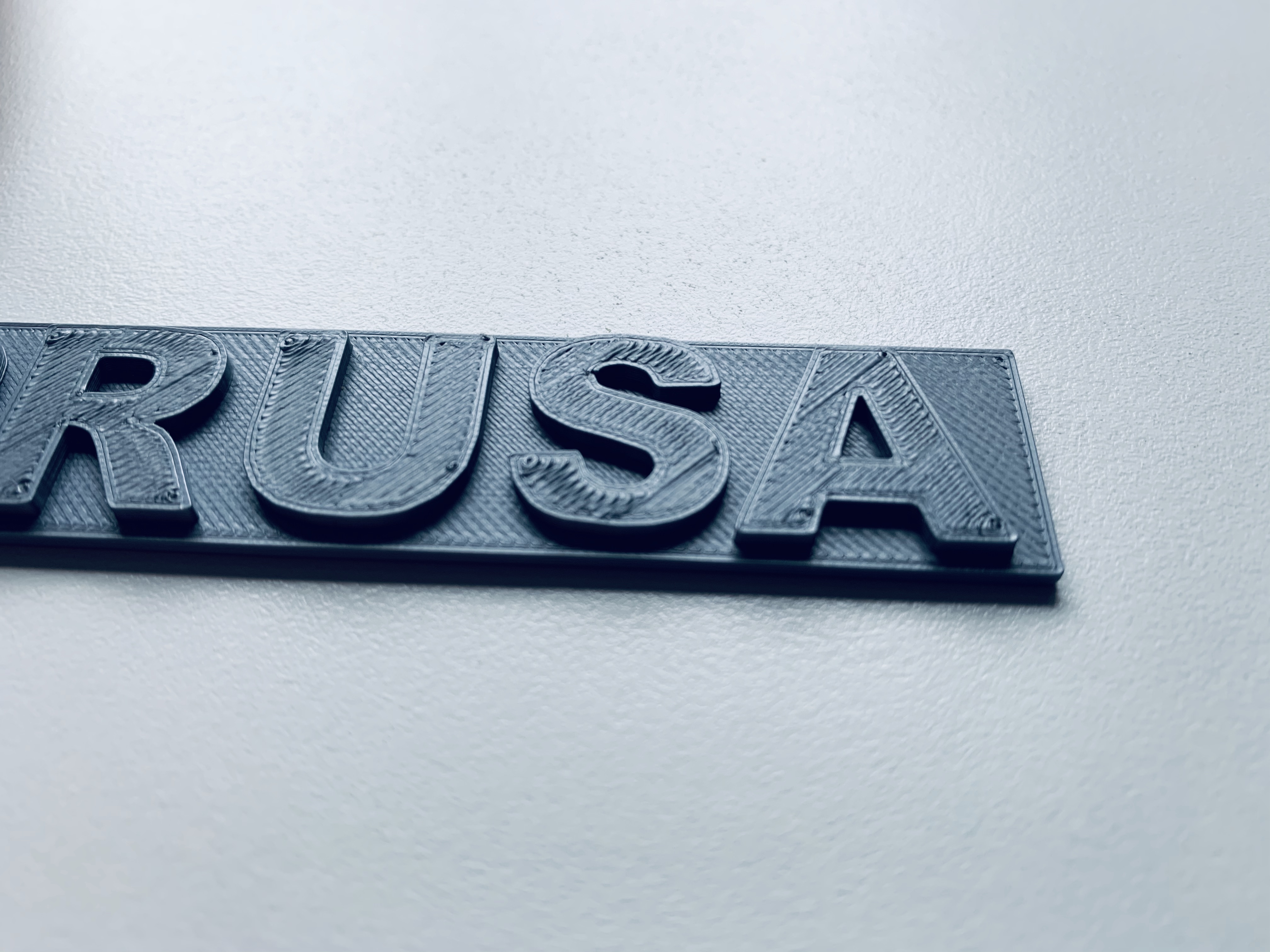
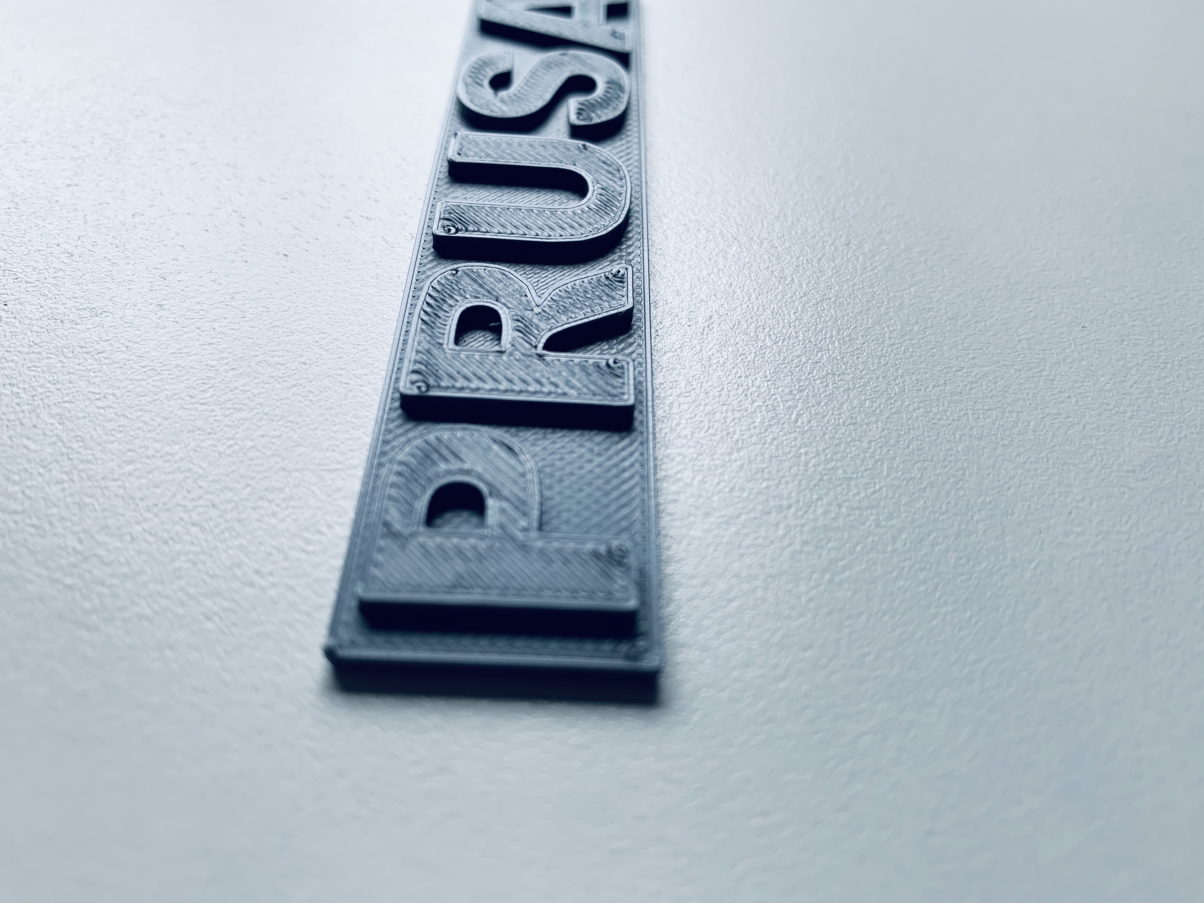
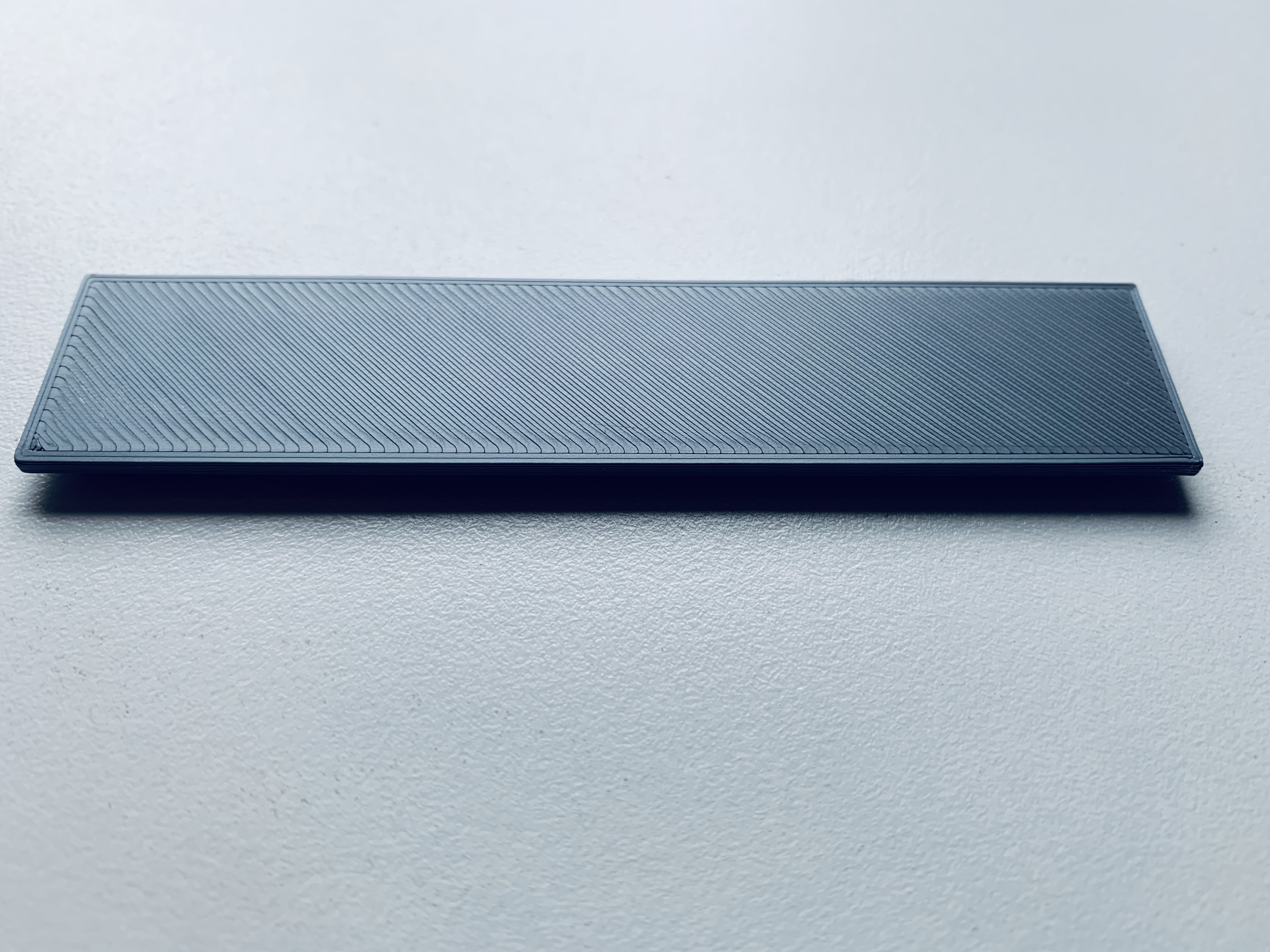
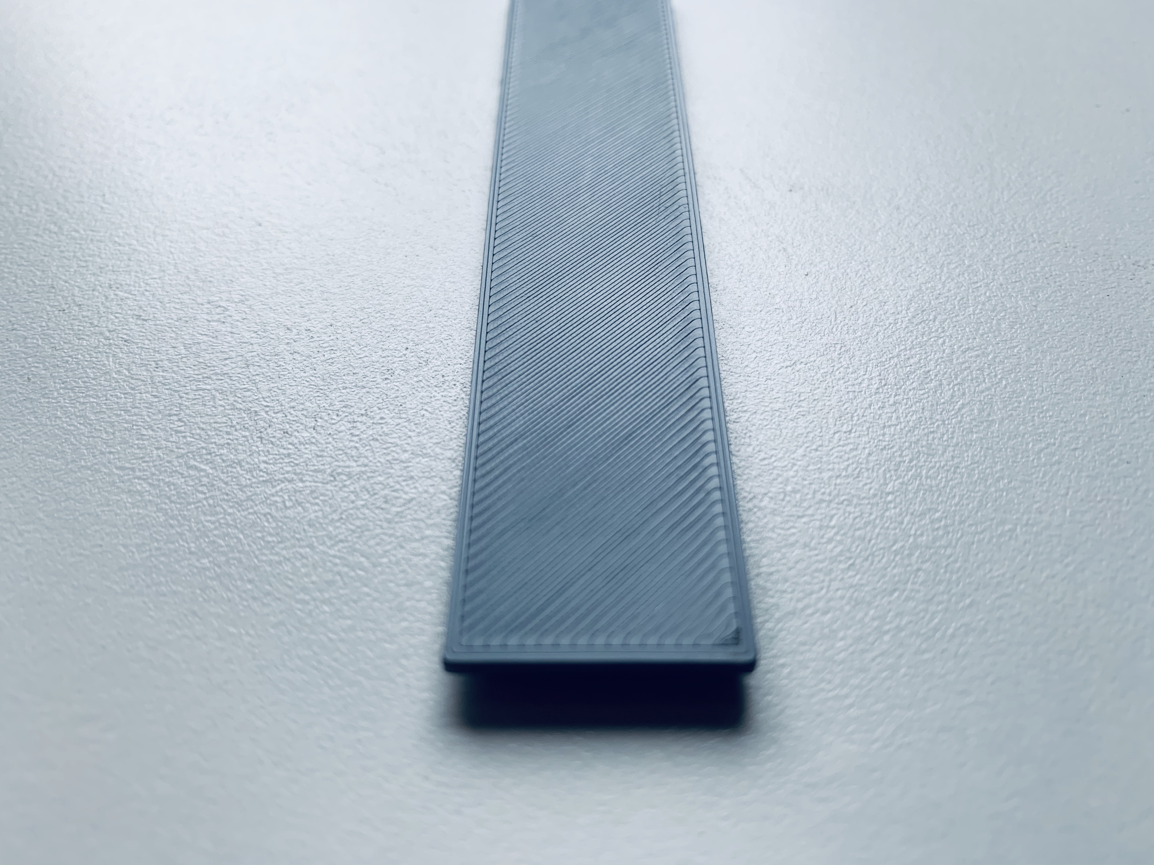
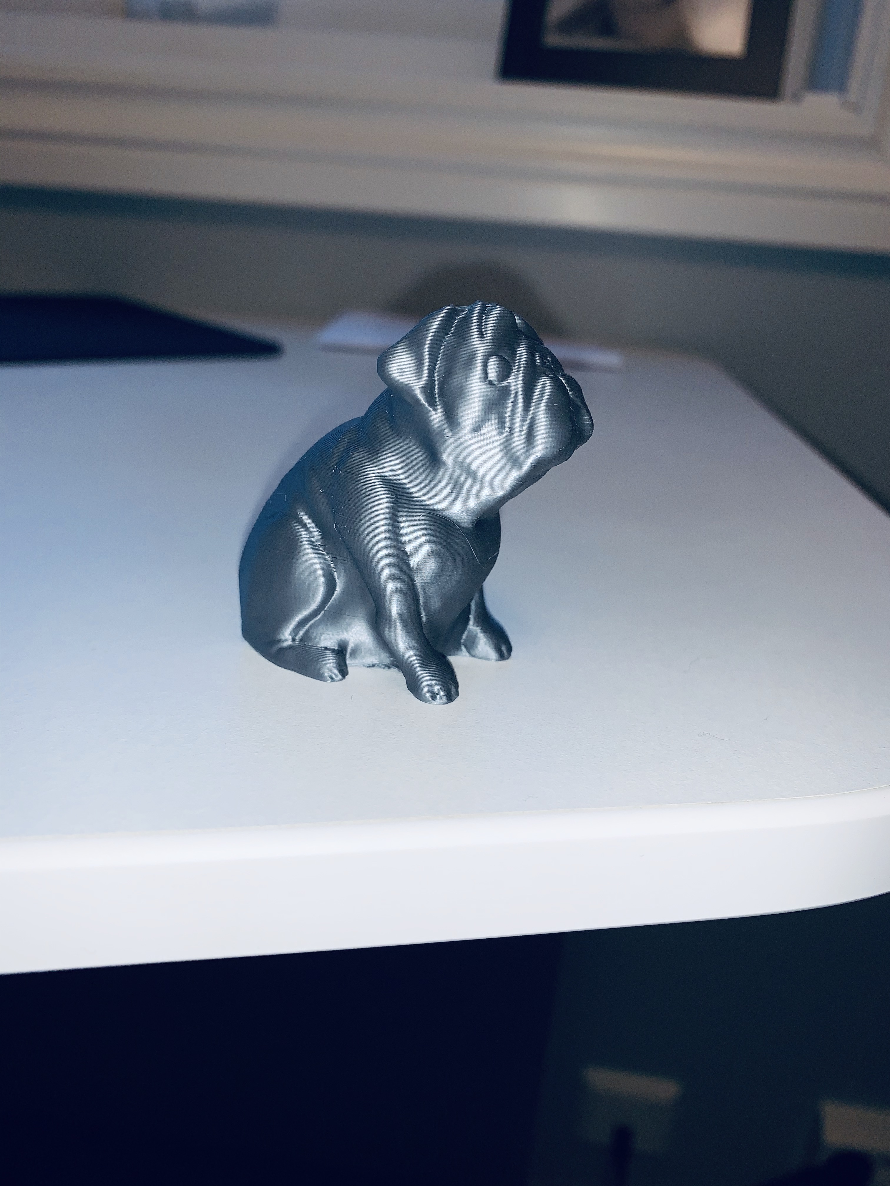

Reaching out to the community, hoping someone has good suggestions.
Tor-Einar
RE: life adjust Z - my way
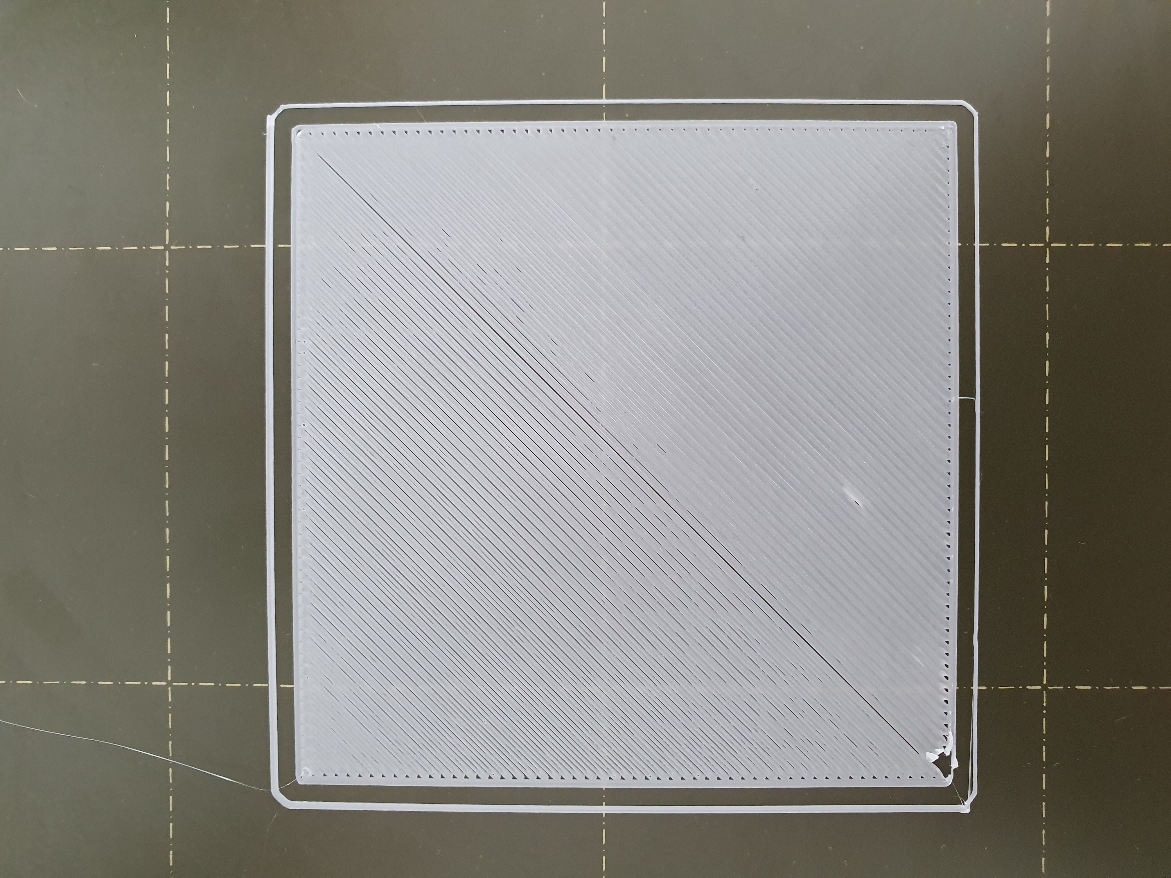
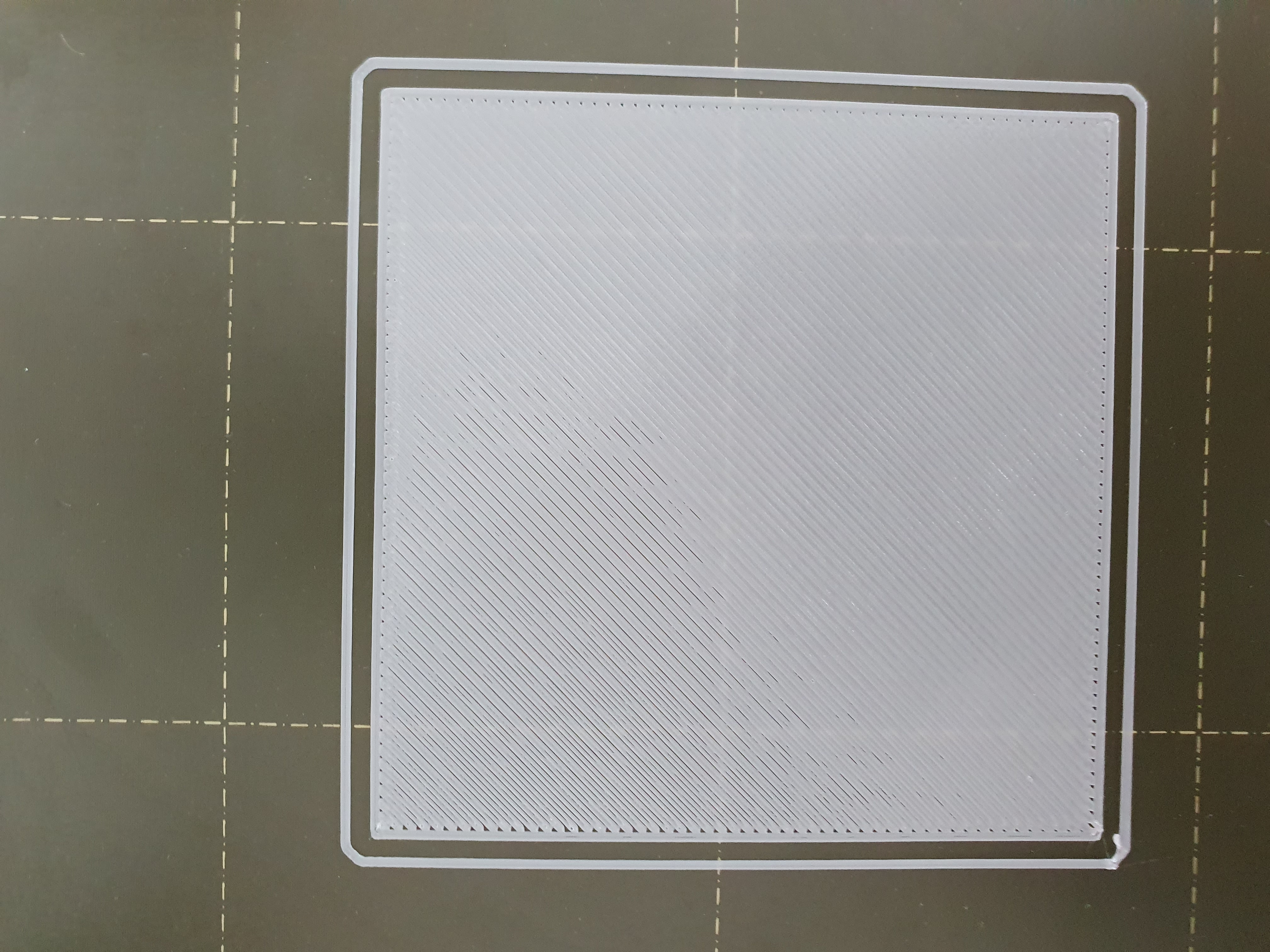
Howdy everyone, finished my build and am calibrating. Would anyone mind giving me some advice on this output? I tried the bed leveling file with all the squares first, noticed it was too squished at -.925, so I did the z adjustment again and set it at -.875. Then I ran the sample file from this thread to see the output and got the following. I noticed some small areas (top middle), think I need to lower the nozzle slightly or is this due to something else?
RE: life adjust Z - my way
@rythomas
Hi,
I'm not an expert at all, to me it looks good, would do the test again.
The idea of this test is to change the Z-value manually up or down when the alarm sounds (midway), then compare the two sides.
RE: life adjust Z - my way
Your photo looks reasonably close to me, but again, a photo straight on like that may have some detail that's not evident.
Are all of the squares across the plate consistently like that, or do they vary?
RE: life adjust Z - my way
@rythomas
Hi,
I'm not an expert at all, to me it looks good, would do the test again.
The idea of this test is to change the Z-value manually up or down when the alarm sounds (midway), then compare the two sides.
Your photo looks reasonably close to me, but again, a photo straight on like that may have some detail that's not evident.
Are all of the squares across the plate consistently like that, or do they vary?
Thanks for the replies, I started doing the Z Adjust mid way through after doing some prints yesterday. Weirdly enough I got all the way back up to -.925 with no squish and it removed any spaces where the edges met the diagonals. I tried measuring with a caliper as well, I got between .18 and .20 on the -.925, could be how I measured but it seems pretty close to me so I will stick with this setting for a while I think.
RE: life adjust Z - my way
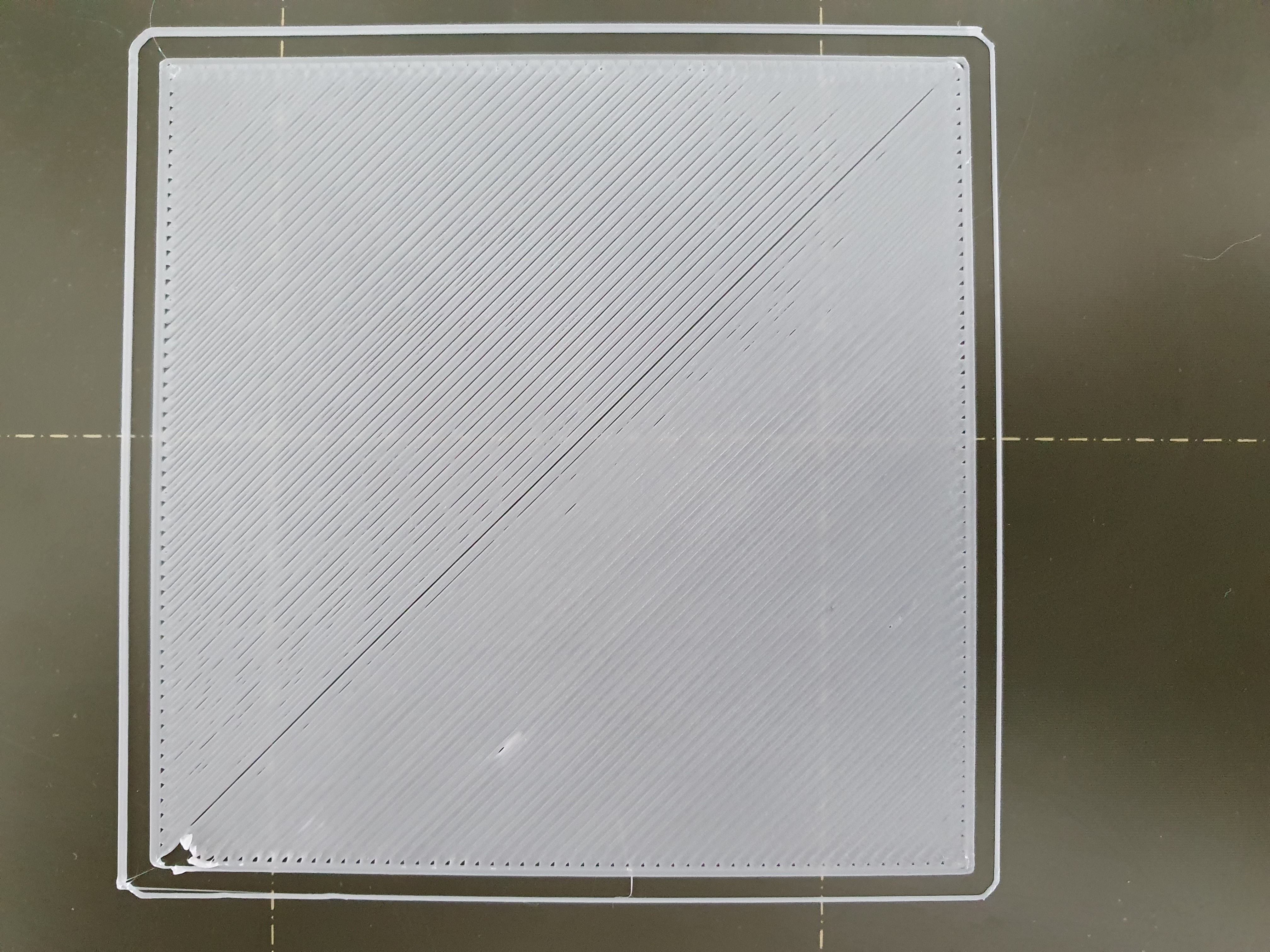
I'm still working on dialing this in and wil run a bunch more tests but I'm currently at -1.05 and, while the square starts off looking pretty good, it gets progressivley worse to the point that there are obvious gaps in between the lines by the time it reaches the far corner.
This is the first time I've built a printer so I'm wondering if I just might have assembled something wrong. I will say I was able to print 3d benchy in the middle of the plate, though with some issues, which is why I found and started running this test.
RE: life adjust Z - my way
@kbrec85
What I ended up doing was this test, dialing it in by moving by .10-.15 in whichever direction on the second half of the square it was needed (if lines were bunched, popping up, squeezing, move it +10, if they were not touching, gaps at the intersections, -.10). Then I would take a pair of calipers and test both sides of what I printed, seeing how close to .20MM I was. I labeled each square and when I had a good amount and though I had the right setting (there were many right at .20MM, like .21, .19, etc) I printed the 3 x 3 prusa test pattern. In my case I noticed some squishing in the corners, so I backed off the nozzle about.5 -.10 and re ran, no squishing in the corners and the center still looked fine. I then did another one of these patterns with that setting and confirmed it was still good.
After all that I put on the textured sheet and did it all over again, and realized you cant really get down to .20MM on the textured sheet, I would shoot for .25MM based on what I read. It looked correct pattern wise with no squishing or raising in my case.
RE: life adjust Z - my way
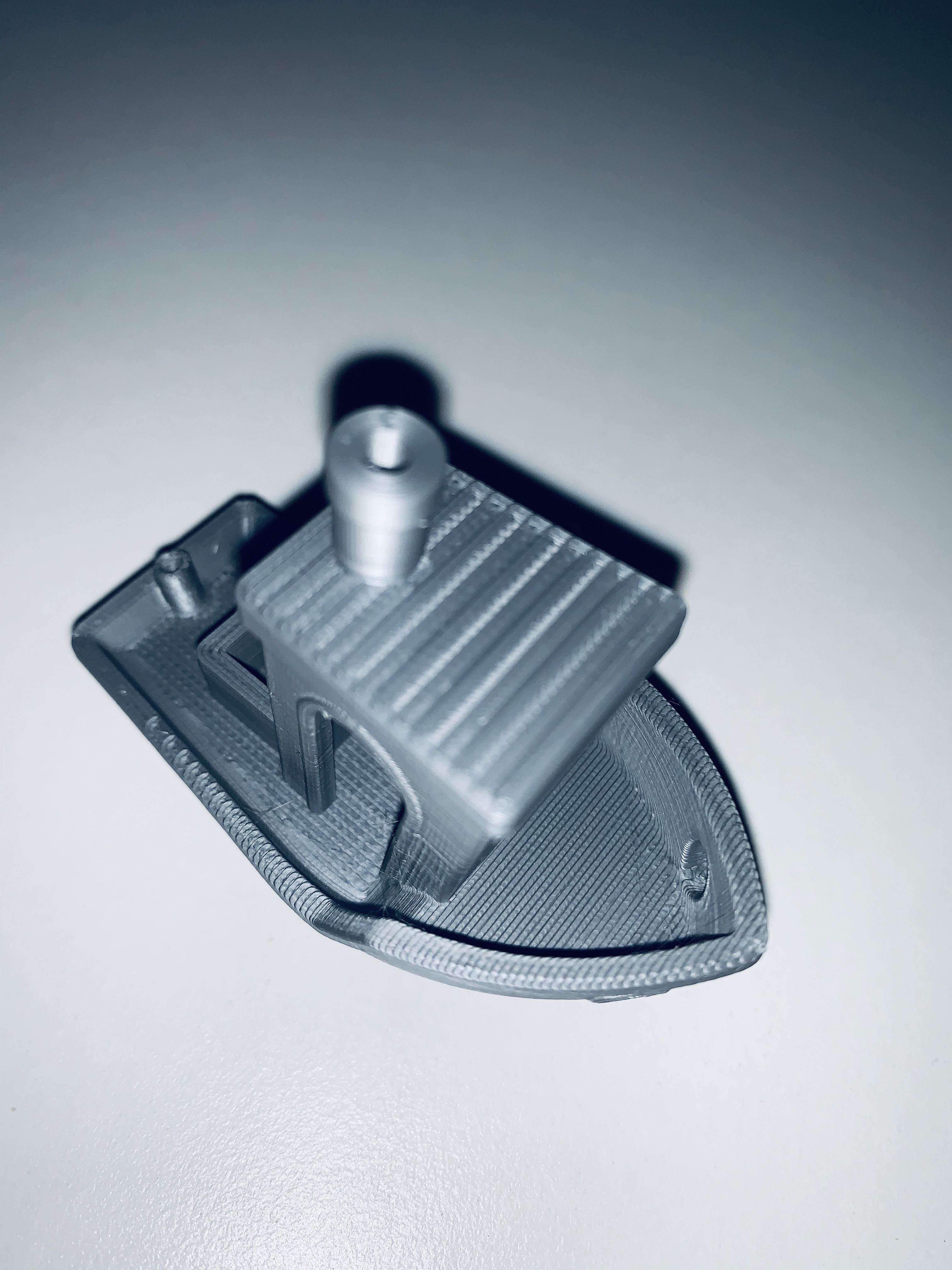
Just to see what happens, I'm printing out 2 side by side 75MM circumference dnd bases and its printing out the first layer mostly fine at -1.05, but there are a few artifacts that look like the nozzle is too close to the bed on the farthest from center parts of both circles.
RE: life adjust Z - my way
I'm still working on dialing this in and wil run a bunch more tests but I'm currently at -1.05 and, while the square starts off looking pretty good, it gets progressivley worse to the point that there are obvious gaps in between the lines by the time it reaches the far corner.
This is the first time I've built a printer so I'm wondering if I just might have assembled something wrong. I will say I was able to print 3d benchy in the middle of the plate, though with some issues, which is why I found and started running this test.
Once you get this approximate, if you think there is some irregularity, as in significant differences between the front/rear or left/right of the build plate, you can do an advanced calibration and compensate for the areas that appear to be higher/lower.
My experience is that once you have the Z calibrated, it stays put unless you change something physical on the machine. I installed the MMU2S and it did not change. I also replaced the fan shroud with again no change. It's still a good thing to check any time you do anything to the extruder assembly.
RE: life adjust Z - my way
Hi,
Just a thought for the guys that just installed their first printer and did this test of 75x75mm. (I'm new myself and realized my error).
I downloaded the gcode for this test pattern, but the temp. setting in this was way higher than what my PLA printed best in. I sliced this 75x75mm with the temp. that gave me the best print. And all of a sudden my z-calibration became easy to adjust.
Just a thought.
RE: life adjust Z - my way
jeffjordan i felt the need to express my gratitude to your method: simplicity is the keyword!
i've come from a wanhao duplicator 2 where bed leveling was a P.I.T.A. (not a pinda XD) and utterly impossible to obtain a decent result.
I've bought a Factory Assembled MK3s and whoa....a whole new world! but....I'm kinda picky and curious so i've fiddled around and stumbled on your website! BINGO!
Long story short...
I've put to practice your STL and BAAAM! god i just love the result!
My setup:
- mk3s factory assembled
- octopi
- pei sheet smooth (diligently washed with dish soap rinsed and washed again and DID NOT touch any part with my fingers, i do prefer dish washer instead of IPA, i run an IPA clean every 10 prints)
- 7x7 calibration pattern 49 points
- 3 point
- Silver PLA made by prusa (not prusament)
so long story short:
1st i got a run with the values i've obtained after a dozen rounds of the calibration pattern V2 provided by prusa which is confusing for who is a newbie but less than perfect who did already experienced bed leveling calibration. then i used the jeff's pattern


so the sweet spot i guess it's between 950-970
my measurement made with a digital caliper (MIND not a micrometer which i'll buy)
are:
- 920 0.21
- 930 0.21
- 940 0.21
- 950 0.20
- 960 0.20
- 970 0.20
- 980 0.21
- 990 0.22 some small stringy bits
- 1000 0.23 rough
- 1010 0.26 + rough
the small blob on the left was caused by the 920 brim which is super high and did not sick properly on the last bit of the perimeter or just an overextrusion
again Jeff THANK YOU!!!!
RE: life adjust Z - my way
Hey guys,
sorry if this was asked already but I'm not really sure for my case. This was all printed with the same z offset. Could this be a warped bed? The printer is a Prusa i3 MK3S. If it is a warped bed, what should I do? If it isn't, what could it be? Otherwise I'm just wondering how to adjust bed leveling.
RE: life adjust Z - my way
Hi Matic,
are you using 7x7 mesh bed levelling?
have you checked that the X axis is level, by driving it up to the top of the frame and ensuring that both sides stall against the end stops?
have you checked that both U rails are seated properly in the cups?
have you checked that the frame is level? doesn't rock from corner to corner?
regards Joan
I try to make safe suggestions,You should understand the context and ensure you are happy that they are safe before attempting to apply my suggestions, what you do, is YOUR responsibility.Location Halifax UK
RE: life adjust Z - my way
@joantabb
Hi,
didn't know about the 7x7 mesh bed leveling at first, the results were much better than at first to say nonetheless.
But, as you can see, there are still visible lines on the model.
I suppose you meant the Z axis, and they stall at the end stops.
I am not sure at what you meant with the U rails, but if you meant if the bed is tightened to the rails properly, it is.
I suppose you mean the frame which every component attaches onto, that's tightened and properly mounted too.
RE: life adjust Z - my way
Sorry Matic.
I meant the Y rails, and the U cups on the frame. if one of the rails is not properly seated in the u cups, then the motion of the Y axis, will have a slight twist in it.
when I built my first printer, I didn't realise that the work surface had a twist in it...
so when I ensured that the four corners were touching the work surface, I was actually building a twist in the frame...
If your printer is currently firm on all four feet, (Doesn't rock from corner to corner)
Try lifting the entire printer, by the top frame, and turn the printer 90 degrees. then put it down again, it should still be firm on it's four feet.
If it now rocks from corner to corner, then both your work surface and your printer frame are twisted...
I took my printer to the kitchen work surface which was not twisted, and re tightened the frame
Admittedly that was a Mk1 printer with the Threaded bar frame, which is MUCH easier to assemble twisted than the Mk3 Frame.
but you can get similar issues with the Mk3 frame.
I have a Geeetech with a Perspex frame and threaded rods, which is diabolical for twisting... you have to be incredibly careful when moving that printer...
Best of luck,
Joan
I try to make safe suggestions,You should understand the context and ensure you are happy that they are safe before attempting to apply my suggestions, what you do, is YOUR responsibility.Location Halifax UK