Testing the LCD
Hi all
I recently replaced the extruder fan on my MK2 and in doing so I've managed to damage either the screen cables or the board.
Basically my LCD no longer lights up, and when connected to my raspberry pi, the init SD card command fails.
I took out the LCD cables to get to the extruder fan cables but have put them make now and checked several times that the orientation is correct.
Likely I have damaged one or both cables or some static may have damaged part of the board.
Does anyone know of a way of testing the LCD without the Rambo board? I have a raspberry pi, arduino (mega and regular), cables, resistors, transistors, etc.
Thanks
Re: Testing the LCD
Maybe you put them on the wrong way around (not the position of the knob but switched the cables).
One cable is for the LCD and the other cable is for the SD Card.
So maybe switch the cables on the Rambo Mini side.
Re: Testing the LCD
@david:
if you are familiar with arduino & co, just hook the lcd up to one of your uno/duo/nano/mega's. you'll know how to do so, when you know the used lcd pins: therefore you could find the schematics here.
but beware, at our "original prusa lcd board" the coded plugs are mounted the wrong way around, so that pin#1 (which usually is encoded with the red wire at the ribbon cable) is pin#10 instead.
they did this to achieve the cables point downwards (instead of upwards) but that confuses people like me (and you ?) who try to follow design rules (instead of playing: "match the photos" of the assembly guide). as my kit arrived and i assembled it, i trapped into the same pitfall and connected the plug at the rambo in the direction that the red wire connects to pin #1 .... but that's not the way joseph designed it  .
.
dem inscheniör is' nix zu schwör...
Re: Testing the LCD
Thanks for the reply.
The problem is that the cables don't go direct to the LCD, they go to a board that has the SD card reader on which the LCD is soldered to.
I could unsolder the lcd display, but even if I test that it works fine, I still wouldn't know whether it's the Rambo mini board or the board the LCD is connected to.
If you know how to test the complete SD card/LCD board that would be great.
Thanks
David
Re: Testing the LCD
...
The problem is that the cables don't go direct to the LCD, they go to a board that has the SD card reader on which the LCD is soldered to...
🙄
yes, that's the way the lcd, the knob, the buzzer and the sd card reader are assembled together to form the LCD 2004 module that is used at our i3 / mk2 and a few other 3d printers !
➡
but as you can read* from the schematics (i've posted the link above), you can get access to the 4x20 character lcd module through connector #1 (EXP1), there you get access to all required pins ! you don't need more pins than +vcc, gnd, lcd7, lcd6, lcd5, lcd4 and lcd enable to control the display with a sketch at one of your arduinos (simply use the hello world example from the LiquidCrystal.h library).
*) i assume that you can read schematics, because you mentioned your arduinos... so i guess that you don't only possess them and assumed you've used them before 😕
so you can check at least the displays functionality....
dem inscheniör is' nix zu schwör...
Re: Testing the LCD
Ok, so I tried switching cables again on the Rambo and I've managed to get some success.
If I have just cable one in, the display mostly works. It displays the right information and the knob click works, but turning it has no effect.
If I plug in the second cable the Lcd shows white squares.
Potentially the sd card board or the cables are damaged.
Re: Testing the LCD
💡
just to let you know: a few minutes ago i tested my spare lcd modules.
to do so i had to extend the ribbon cable for about 65cm:
2 pieces at 30cm with some multi-pin connectors in between to change the orientation (because the connectors at these modules show the correct orientation !).
from the electrical point of view, that degrades the bandwidth of data transmission through the cable severely (3 additional joints where the surge impedance of the ribbon cable is violated).
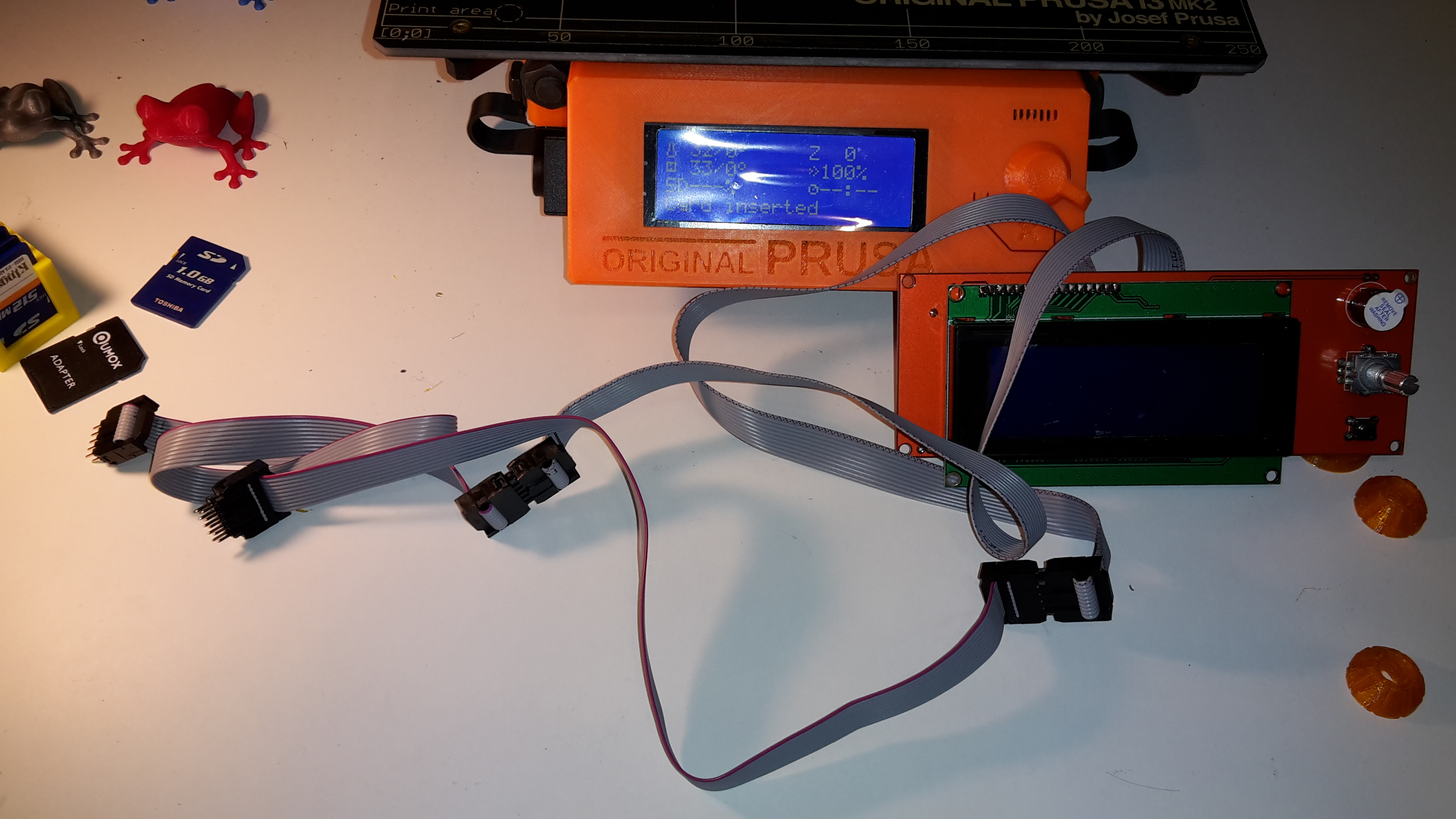
:geek: with that extension lcd, buzzer, rotary encoder & pushbutton and reset switch worked fine. even inserting an sd card was detected... but no successful reading was possible (managed once to get a listed directory with an old sd card, but failed the second time).
➡ so if someone encounters problems with reading sd cards: use a shorter ribbon cable, or at least check the cable at EXT2 (the one with the two markings) for damages or pinches.
dem inscheniör is' nix zu schwör...
Re: Testing the LCD
I think I'm going to try replacing the ribbon cables and the screen.
Does anyone know where I can buy these?
I can find the screen on ebay, but not the sd card board as that appears to be a custom board for this printer.
Re: Testing the LCD
you can find the complete LCD 2004 display smart controller (incl. sd card reader) at ebay. for example here
you then only need two 10pin ribbon cables of the correct length, with connectors, because the ones that come with the board are only 30cm each.
dem inscheniör is' nix zu schwör...
Re: Testing the LCD
Thanks, I've ordered a replacement which should hopefully arrive my next week.
Re: Testing the LCD
hi dave
when you ordered it from the link i posted above, it'll take more than an week, because they send it from hong kong. my order took 17 days to arrive here (in germany).
😕
but if you've ordered it from a more local supplier (like amazon) it'll probably be much quicker.
😀
💡
by the way, just checked the spare lcd with short cables connected directly to the rambo (with the red wire of the ribbon cable oriented to pin#1 (as it should be)) and it worked fine, even the sd card reader.
dem inscheniör is' nix zu schwör...
Re: Testing the LCD
...
The problem is that the cables don't go direct to the LCD, they go to a board that has the SD card reader on which the LCD is soldered to...
🙄
yes, that's the way the lcd, the knob, the buzzer and the sd card reader are assembled together to form the LCD 2004 module that is used at our i3 / mk2 and a few other 3d printers !
➡
but as you can read* from the schematics (i've posted the link above), you can get access to the 4x20 character lcd module through connector #1 (EXP1), there you get access to all required pins ! you don't need more pins than +vcc, gnd, lcd7, lcd6, lcd5, lcd4, lcdrs and lcd enable to control the display with a sketch at one of your arduinos (simply use the hello world example from the LiquidCrystal.h library).
*) i assume that you can read schematics, because you mentioned your arduinos... so i guess that you don't only possess them and assumed you've used them before 😕
so you can check at least the displays functionality....
dem inscheniör is' nix zu schwör...
Re: Testing the LCD
I tried out new cables for the LCD and everything is working fine.
Thanks for your help.