How was V2Calibration created?
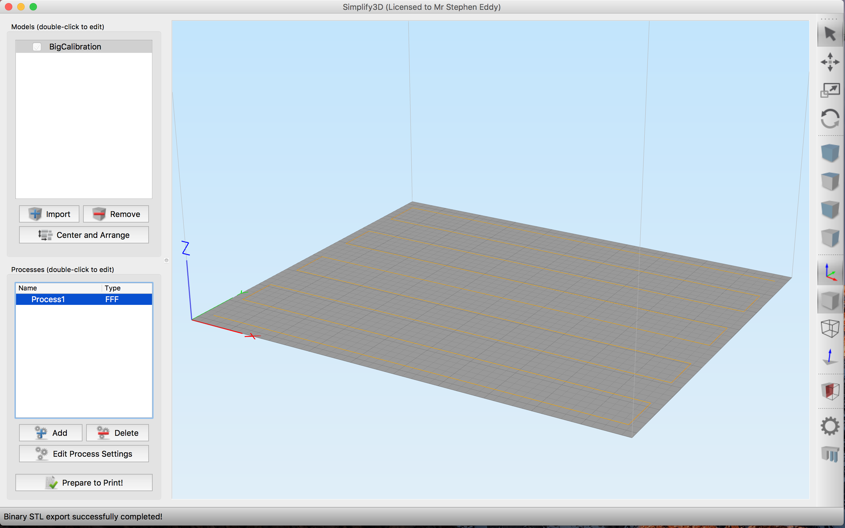
I am trying to create a bigger version of V2Calibration.gcode that covers the entire bed and has more lines. I tried modelling it using Fusion 360 as a square tube which is 0.2mm high and wide and cover the bed.
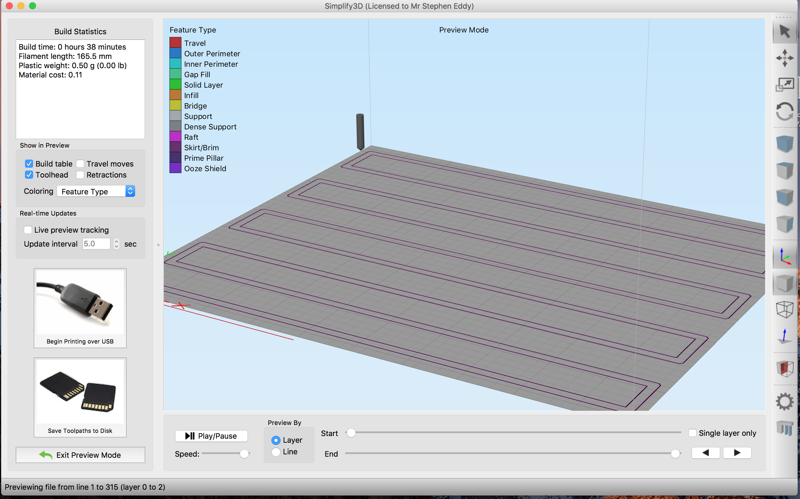
This looks like it worked when I bring it into Simplify3D, but when I preview the print all it prints is the brim and not the line. I tried printing out the brim which does work and covers the whole bed, but it took 35 minutes to print moving the head incredibly slowly.
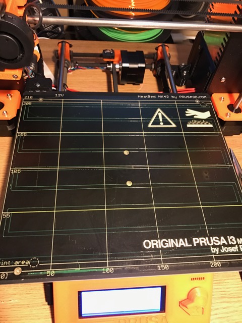
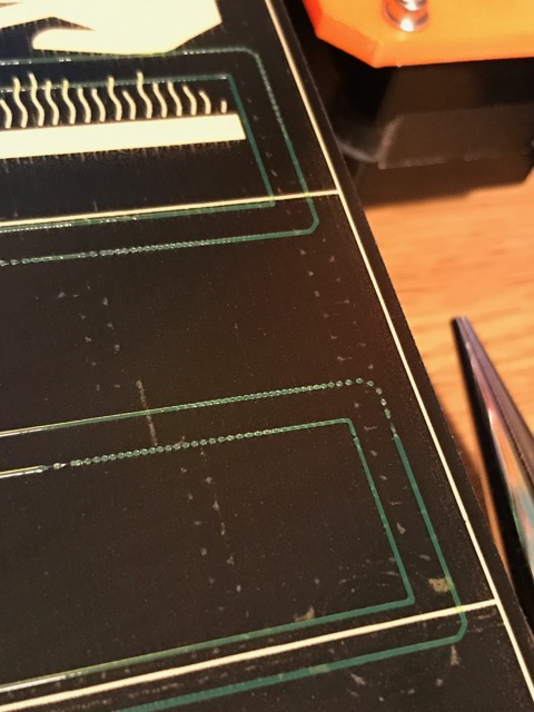
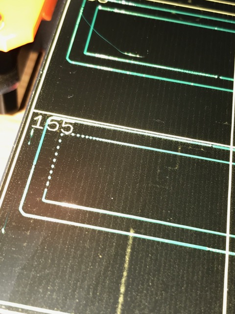
Also, the printed filament is missing in places showing rows of dots. Not sure if this is a fault of the filament or a fault of how the line is being printed.
Here is how the model and the preview looks in Simplify3D:
And here are some images of the print and issues:
Re: How was V2Calibration created?
For some reason it would only let me attach 2 images. Here are the closeups.
I have included the GCODE and STL file links below. Would appreciate any comments or help in making a bigger calibration model.
https://dl.dropboxusercontent.com/u/7799729/3Dprint/BigCalibration2.stl
https://dl.dropboxusercontent.com/u/7799729/3Dprint/BigCalibration.gcode
Thanks
Re: How was V2Calibration created?
I've created another one which is slightly smaller and is 0.4mm wide and 0.2mm high. Still Simplify3D will output nothing.
Here is a part of the GCODE output. As you can see, it outputs nothing where it should be.
G28 W ; home all without mesh bed level

G80 ; mesh bed leveling

G1 Y-3.0 F1000.0 ; go outside printing area

G1 X60.0 E9.0  F1000.0 ; intro line

G1 X100.0 E12.5  F1000.0 ; intro line

; layer 1, Z = 0.2

; layer end

M104 S0 ; turn off temperature

M140 S0 ; turn off heatbed

M107 ; turn off fan

G1 X0 Y200; home X axis

M84 ; disable motors
Re: How was V2Calibration created?
I've managed to slice the updated one with Slic3r and it works great.
It's here if anybody wants it:
https://dl.dropboxusercontent.com/u/7799729/3Dprint/V3CalibrationSlic3r.gcode
Re: How was V2Calibration created?
What are your settings in S3D? What is extrusion width set to?
I've created another one which is slightly smaller and is 0.4mm wide and 0.2mm high. Still Simplify3D will output nothing.
Here is a part of the GCODE output. As you can see, it outputs nothing where it should be.
G28 W ; home all without mesh bed level

G80 ; mesh bed leveling

G1 Y-3.0 F1000.0 ; go outside printing area

G1 X60.0 E9.0  F1000.0 ; intro line

G1 X100.0 E12.5  F1000.0 ; intro line

; layer 1, Z = 0.2

; layer end

M104 S0 ; turn off temperature

M140 S0 ; turn off heatbed

M107 ; turn off fan

G1 X0 Y200; home X axis

M84 ; disable motors
Re: How was V2Calibration created?
All default settings for the RC4 profile. Extrusion width at 0.2 layer height is 0.45mm (manual).
Thanks
Re: How was V2Calibration created?
If you mean that layer height is .2 and extrusion width is .45 then that makes sense. S3D has issues with thin walls. Set your extrusion width to the same or just slightly smaller/thinner than your model width. So, if the model line is .4mm wide then set extrusion width to .4 or to .39.
