Correction of inner diameters
I am designing a bracket that is supposed to fit exactly on a square tube with external dimensions of 15x15mm. However, according to the printout, the holder cannot be pushed over the pipe because the internal dimensions of the pressure part are too small.The question: Does the design have to take into account the nozzle diameter, = 0.4mm, be taken into account because the print head traces the construction line exactly? In this case, 0.2mm, = half the nozzle diameter, would be too much on each side?In CNC milling, there is a setting called "radius correction inside". This ensures that the cutter moves with its outer edge along the inner edge of the construction line and then the inner dimensions also fit.
Slicer is the Prusa Slicer 2.4.1, printer MK2S. Is there a similar setting option in this configuration?
Thank you very much for your answer.
Translated with www.DeepL.com/Translator (free version)
There is a variable amount of lateral spread, squish, as each layer is laid down and this varies with filament, the degree of external slope and extrusion multiplier. Also there is thermal expansion - or the amount of contraction as the part cools, to account for.
The best practice is to calibrate with trial prints and then to print a slightly tight fit and post-print machine to fit.
Cheerio,
RE: Correction of inner diameters
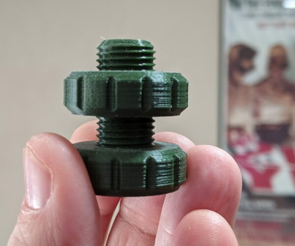
If you are after dimensional accuracy, the closer your slicer settings match your physical printer and filament, the better your results will be. I was frustrated trying to print threaded parts designed in Fusion 360 until I realized the importance of extrusion adjustments and particularly calibrating your filament extrusion multiplier to closely match your actual filament values. Once I did this, I am able to 3D print threaded parts designed using the Fusion 360 defaults with no additional manual tolerance adjustments. For example, the threaded nut on this fidget toy spins freely.
This adjustment also helps reduce stringing and distortion.
It doesn't help that PrusaSlicer makes some behind-the-scenes adjustments to flow rates. I have some notes on this here that might be helpful. I also have notes on my process for dealing with print inaccuracies here that are more focused on stringing but apply to accuracy in general. Also remember that any moisture absorbed by your filament will play havoc with accuracy, often distorting those inner surfaces. Be sure you filament is dry when accuracy matters (see notes pages).
and miscellaneous other tech projects
He is intelligent, but not experienced. His pattern indicates two dimensional thinking. -- Spock in Star Trek: The Wrath of Khan Unfortunately,…
RE: Correction of inner diameters
There is an option "XY slice compensation" in Print Settings/Advanced/Slicing in Prusa Slicer.
A more detailed setting is in Super Slicer, called "XY compensation" in Print Settings/Slicing/Modifying Slices.
If I understood correctly, theese settings are what you might need ...
RE: Correction of inner diameters
Hi Guys,
thanks for your quick answers. I fomulate my posts in german and translate with Deepl, so
don't wonder if something is not that precise formulated.
What the hell is " filament extrusion multiplier" and where do i find this setting in Prusa slicer?
RE: Correction of inner diameters
Its better known as flowrate if I understand correctly.
Da habe ich mir extra die Mühe gemacht, Prusa Slicer auf Englisch umzustellen, um den genauen englischen Menüpfad zur XY-Kompensation anzugeben... 😉
RE:
[...] What the hell is " filament extrusion multiplier" and where do i find this setting in Prusa slicer?
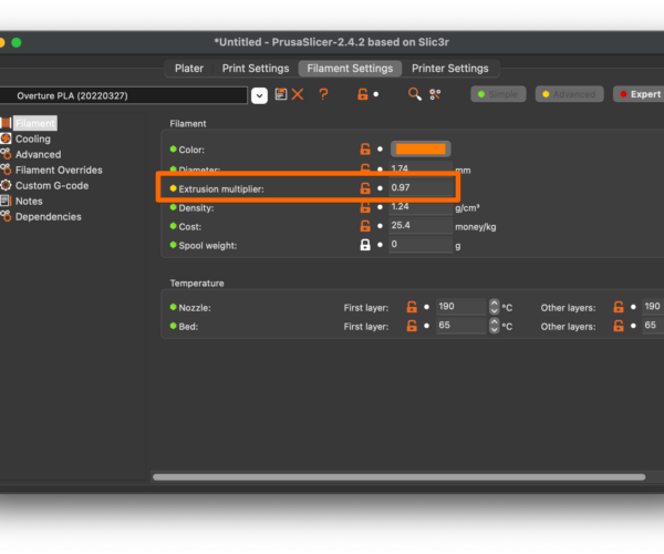
Sorry. It's spelled out on the notes pages I linked to. Look for Filament Settings->Filament->Extrusion multiplier.
And yes, it is referred to as flow rate (e.g., gcode M221) BUT be careful. Those are different settings and both are applied. Slicer settings affect slicing results. Gcode M221 affects printer flow rate. You don't want them fighting each other. Please refer to the 1st page of notes I linked to for details.
and miscellaneous other tech projects
He is intelligent, but not experienced. His pattern indicates two dimensional thinking. -- Spock in Star Trek: The Wrath of Khan Unfortunately,…
RE: Correction of inner diameters
In german settings it is called "Extrusionsfactor", in the display of the printer it is called "flow" and in g-code it is called "set flow percentage" (M221 S...).
RE: Correction of inner diameters
This isn't a criticism. Just a bit of advice based on my own experience:
- REMOVE the M221 line from the PrusaSlicer start gcode, or at least remember that it's there.
- Do NOT use XY compensation until you've tried adjusting extrusion. That setting will make "corrections" to other settings and you can end up making other changes to compensate for those changes. The root problem is over extrusion in many cases. Fix that first.
- Remember that M221 and the flow rate setting on the front panel are the same. If you put or leave the M221 in your start gcode, the printer will use that setting (you can verify on the front panel) and will not reset it until you either enter another M221 or reset the printer. (I always reset M221 to 100% in my startup gcode.)
- M221 affects prints all prints regardless of filament or slicer settings. Slicer settings affect only that print (gcode) using that filament. Better to make adjustments that only affect what you specifically want to affect rather than making changes that affect everything to fix one specific printer. Changing BOTH M221/flow and extrusion multiplier will cause headaches.
and miscellaneous other tech projects
He is intelligent, but not experienced. His pattern indicates two dimensional thinking. -- Spock in Star Trek: The Wrath of Khan Unfortunately,…
RE: Correction of inner diameters
Actually I use M221 a lot. While the z-offset is for optimal adheasion, on a textured sheet the surface is actually not fully closed, you might need a bit of overextrusion just for the perfect look ( for example printing the display case of the mk3s). So I insert custom gcode M221 S115 for the first layer ( it differs a bit, depending if I use Prusa Textured Sheet, Fysetc or Trianglelab) [and also M220 S60 as I use hilbert curve with it many short directional changes, so it should print very slow]. On second layer I return to standard flow for the filament (mostly M221 S95 or S100) and 80% speed (sometimes second layer on top of hilbert curve is a bit problematic) and on the third layer speed to 100%. Actually to get the perfect first layer to look optimal is much harder than just get it to stick...
If you have adjusted flow well (no over/underextrusion), dimension will still not fit: 1. The extrusion is not rectengular. If you print 0.2 layerhight, extrusion is widest in the middle. Inside of the object this eqals out if flow is correct, as the molten plastic is pressed against already printed walls. But on the outer perimeter, this effect is visible - and if you measure outside dimensions or inner diameters, you will always measure the thickest part of a layer. Also vibration or not perfectly constant diameter of filament lead to imperfections. So do not mess with extrusion factor or flow rate to compensate. This is to be solved by adjusting the object. Thats what xy compensation does. It makes outer dimensions of the object just slightly smaler and inner dimensions just a bit bigger. The reason Super slicer uses seperate values for outer and inner dimentions is round holes are made from polygons. So a hole converted into a polygon become always a bit smaler. So some extra is to be compensated, if you have round holes in an object with straight lines.
For flow and extrusion factor you are totaly correct. They do the same, but in a different way. Extrusion factor is used to calculate e-Value in gcode. Flowrate is set for printer related things (like increasing flow for the first layer on a textured bed) - and of course quick corrections (if you have to increase flow on the panel for a new filament on the fly, you can use this to recalculate extrusion factor in filament settings). A third parameter are eSteps. Together they result in "total flow".
Actually extrusion multiplier is used also to compensate eSteps. eSteps depends on the effective diameter of the gears. This depend of how deep the tooths get into the filament. This depends on how hard and stiff the material is. So you can only calibrate eSteps for one material (mostly for PLA). The Extrusion Factor stored for the filament takes not only the other characteristic into account, but also the effective diameter change (actually this effect seems to fade, as gears become bigger and bigger - from Bondtech dual gears to orbiter gears to LGX to Prusas new XL gears. As bigger the gears are, as lower the effect of effective diameter change)
RE: Correction of inner diameters
Thanks for all your replies guys.
It seems a lot of experimentation is necessary. The first thing I'm gonna try is, as mentioned in my initial post:
Desired inner diameter of the end product = 15mm, construction diameter is 15.4mm.
Assuming that the nozzle, 0.4mm, exactly follows the construction line, putting a 0.4 mm wide string of filament to the heatbed, resulting in an overhang on both sides of 0.2mm.
Regards and have a nice weekend.

