Help. Bed Calibration Anomaly
As many as you are probably aware, I've been having lots of reliability issues with my MK2 since it arrived, with <50% success rates for simple PLA.
Tonight I had a brainwave and decided to measure the differences in the Live Z Adjust figure all over the bed. My printer has been fully X,Y,Z calibrated and setup correctly.
I've taken measurements from all around the bed and included the co-ordinates in the picture below in brackets (X,Y). I avoided the extreme edges where it took the nozzle too close to the edge. I used the calibration paper from my FlashForge to adjust the Live Z value at each point until it the nozzle was at just the right height to put a little bit of pressure on the paper as I moved it under the nozzle. All movements of the axis was performed using the Settings / Move Axis option, after I had first performed an Auto Home operation.
The results are not at all what I expected as can be seen below:
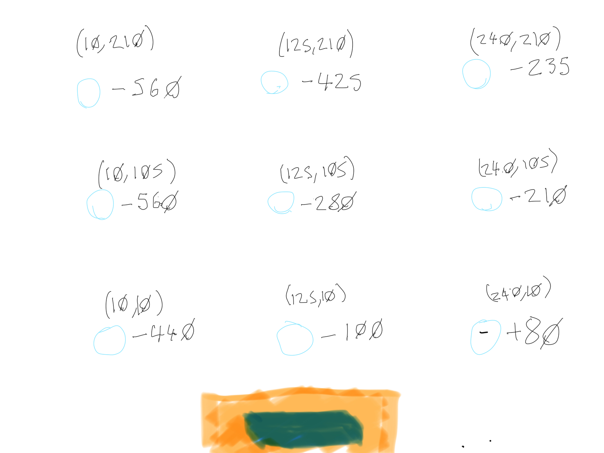
I would have expected the level to be about the same all over the bed given the Mesh Bed Levelling had completed. The Bed Level Correction is set to all zeros. The full calibration reported that the axis were perpendicular.
No wonder I can't get reliable prints. Does anyone have any idea what is happening here and how I might fix it?
Re: Help. Bed Calibration Anomaly
Could the PEI sheet be crook somehow?
I think the PINDA measures distance between PINDA probe and print bed, irrespective of presence of PEI sheet or other layers on the bed.
And your paper test measures distance betwen the nozzle tip and the surface of the PEI sheet.
If the PEI sheet is of uneven thickness somehow, then the PINDA would report a straight bed but printing will not work well.
Re: Help. Bed Calibration Anomaly
As many as you are probably aware, I've been having lots of reliability issues with my MK2 since it arrived, with <50% success rates for simple PLA.
Tonight I had a brainwave and decided to measure the differences in the Live Z Adjust figure all over the bed. My printer has been fully X,Y,Z calibrated and setup correctly.
I've taken measurements from all around the bed and included the co-ordinates in the picture below in brackets (X,Y). I avoided the extreme edges where it took the nozzle too close to the edge. I used the calibration paper from my FlashForge to adjust the Live Z value at each point until it the nozzle was at just the right height to put a little bit of pressure on the paper as I moved it under the nozzle. All movements of the axis was performed using the Settings / Move Axis option, after I had first performed an Auto Home operation.
The results are not at all what I expected as can be seen below:
I would have expected the level to be about the same all over the bed given the Mesh Bed Levelling had completed. The Bed Level Correction is set to all zeros. The full calibration reported that the axis were perpendicular.
No wonder I can't get reliable prints. Does anyone have any idea what is happening here and how I might fix it?
Can you upload a shot of your V2Calibration print instead?
And what Live Z Adjust value are you using when printing that?
Me on MyMiniFactory!
Me on Instagram
3D Printing Live Feeds
Prusa MK2 Usergroup Slack Live Chat
Unofficial live chat by users for users.
Re: Help. Bed Calibration Anomaly
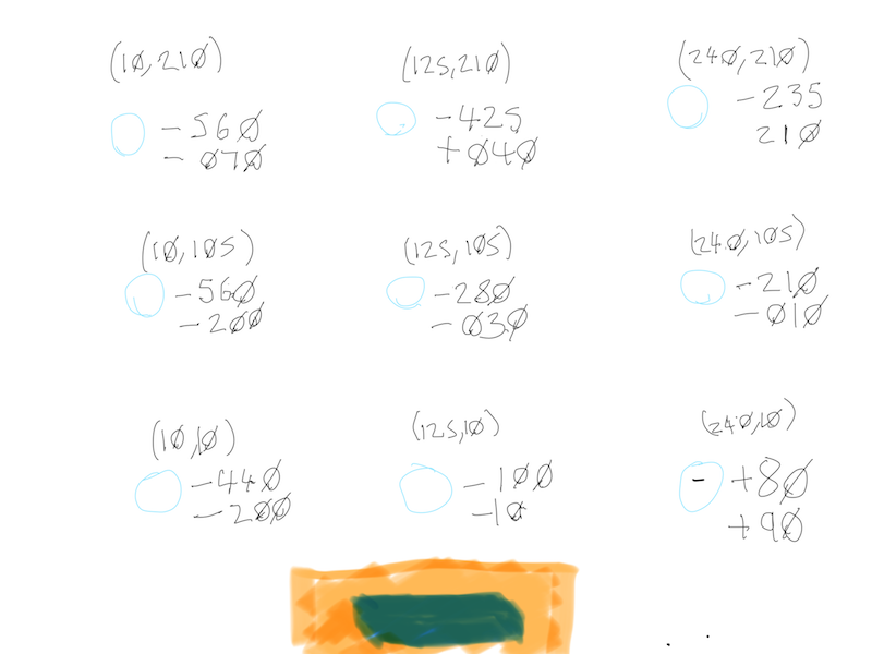
I've had confirmation back from Prusa support that the PINDA probe adjustments are not taken into account when you move the head via Settings / Move Axis, so the Z stays at the same height.
That means those values are reading the actual slant of my bed. I need to put them into a 3d program and plot out what the shape of the bed looks like based on it.
I also notice that in the firmware source code, there is a G81 code to read out the probe measurements stored in EEPROM and send them over serial. However, it looks to me like it is commented out in the released firmware, so I may have to compile a custom version. It would be enlightening to compare them to the measurements using the above method.
RE V2 calibration. I usually have that set to about -0.480 to print, and it will mostly stick then, though in some places it comes of very easily and in overs it is overly squished.
Re: Help. Bed Calibration Anomaly
I've input the above Z offsets into Blender to modify a Plane to see what the resulting tilt of the bed looks like.
Looking at the following render, I can see the issue is mainly my front right corner is raised up far too high and is causing the bed to twist slightly along the X-Axis.
I'm going to check the tightness of the front right screw holding the bed in place and then recheck the heights.

Re: Help. Bed Calibration Anomaly
This is hopeless. I checked the screws holding the bed and they were all tight. There was however a fair amount of play in the bed and the only thing that sees to stop that is the cable ties holding the bearings down. I removed the bed, tightened the cable ties (only one could be tightened by a single notch) then put it back on.
Below are the new readings after performing a Calibrate X, Y, Z (the printer reported axis were perfectly perpendicular). As you can see totally different than before (new figures are the bottoms ones below each point):
In order to compare this to what the probe measured, I homed the printer (G28 W), performed mesh bed levelling (G80) then read out the measured probe data (G81). Figures are below:
Send: G81
Recv: Num X,Y: 7,7
Recv: Z search height: 5
Recv: Measured points:
Recv: 0.31667 0.32417 0.34778 0.38750 0.44333 0.51528 0.60333
Recv: 0.27444 0.29180 0.31631 0.34796 0.38677 0.43273 0.48583
Recv: 0.23833 0.26486 0.29177 0.31907 0.34677 0.37486 0.40333
Recv: 0.20833 0.24333 0.27417 0.30083 0.32333 0.34167 0.35583
Recv: 0.18444 0.22723 0.26350 0.29324 0.31646 0.33316 0.34333
Recv: 0.16667 0.21655 0.25976 0.29630 0.32615 0.34933 0.36583
Recv: 0.15500 0.21130 0.26296 0.31000 0.35241 0.39019 0.42333
Recv: ok
Does anyone understand this well enough? I still can't get consistent first layer, it either is ground into the bed in places or floats above it.
Re: Help. Bed Calibration Anomaly
Did you maybe mount the bed carrier incorrectly?
It is possible to mount it rotated, and then the centre screw will not fit properly into the bed. That bends the bed.
There is a marker on the carrier which needs to be in the right position before you tie the bearings to the bed.
In the manual it is Step 13 of the y-axis assembly.
Re: Help. Bed Calibration Anomaly
Hi, thanks for the response.
I've got to admit that was the most confusing part of the instructions for me, so it is possible. The instructions show both a countersunk hole and a white marker dot. I did not have that white dot, only the countersunk hole. Also later photos where you might expect to have it marked, it isn't.
As mine currently stands, when you are looking from the front of the printer, the countersunk hole is in the back left corner on the top of the carriage holding the bed (side nearest the bed). Is that where it should be?
Sounds right.
Have a look at the photo in Step 22 in Y-axis assembly if you are not certain.
Re: Help. Bed Calibration Anomaly
did you manage to solve this problem?