Pinda v2 temperature study
This is not an appeal for help, but I've recently been investigating the temperature dependence characteristics of my Pinda V2, and thought others might be interested:
I've been assembling a printer from some of the parts of a i3 Mk2.5, but using a Duet3D board running RepRapFirmware. This was because, like many others, my bed power connections melted / burned, so since I had to do something about that, I thought I'd do something different. My resulting printer is probbaly 50% Prusa - it's Prusa motors, bearings, rods, general layout (but it's now a 'Bear' frame), and of particular relevance Prusa V2 PINDA.
I've never really trusted the Pinda temperature compensation, and since first using a V1 I have always done all bed preheat with the printhead as far from the bed as possible to minimise heat effects. One of the advantages of RRF is that it has 'meta gcode' facilities, where you can embed programmed code (loops, conditionals, etc.) into gcode files and the board executes it. This lets me examine the temperature response.
I can probe, heat up the probe by heating the bed (my printer is in an enclosure, so this is fairly effective), then probe again and see how the trigger height of the probe has changed. I thought this would reflect the standard firmware calibration - sitting the head just above the bed for a few minutes while it heated and periodically probing. However, it turns out to not be that straightforward.
My first pass did exactly that - put the nozzle just above the bed, switch the bed on, probe every time the pinda gets half a degree hotter than it was and see what happens. I got this:
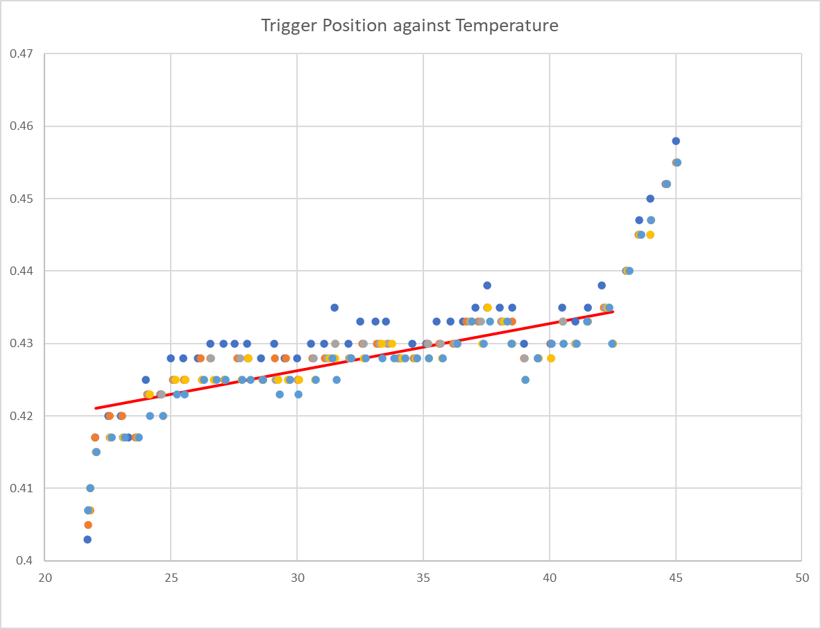
Interesting observations are linearity-ish through the middle, but it's a very small temperature dependence, and the non-linearity at beginning and end. After a number of runs of this I noticed something and when I return to that first data set it's there to see too. This is the graph of temperature against time for that first run:
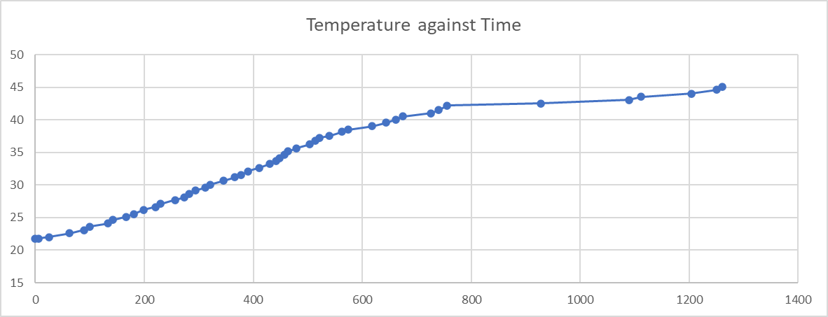
So that dramatic change in apparent temperature coefficient from about 42 degrees correlates with a dramatic change in time it takes to get to each temperature increment. This leads me to think that the thermistor in the probe heats up faster than the electronics - so when the temperature is rising (fairly) quickly, the electronics are actually cooler than reported and so exhibit less apparent temperature dependence.
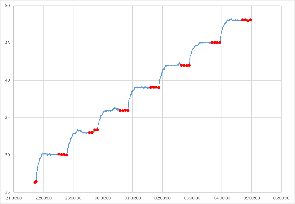
So then I did it again. This time I coded a more complex heating algorithm - it uses PID (but not very tuned) to adjust the bed setpoint temperature as if it was the power input and tries to hold the pinda at a constant temperature for 40 minutes before taking four sets of probe readings at 5 minute intervals, with 3 probes per set and then moving on to the next temperature. Again, this was by embedding code into a gcode file.
This does of course come with the caveat that I’m assuming my bed doesn’t itself move at different temperatures. I suppose I could set up a dial gauge on it (but the only one I have has lost its spring, so not terribly useful).
This is fairly successful (with some cheating on the first cycle to avoid a massive over-temperature spike while the integral term initialises / stabilises) and I typically get a temperature v. time from the pinda thermistor like this (red dots are where probing was done):
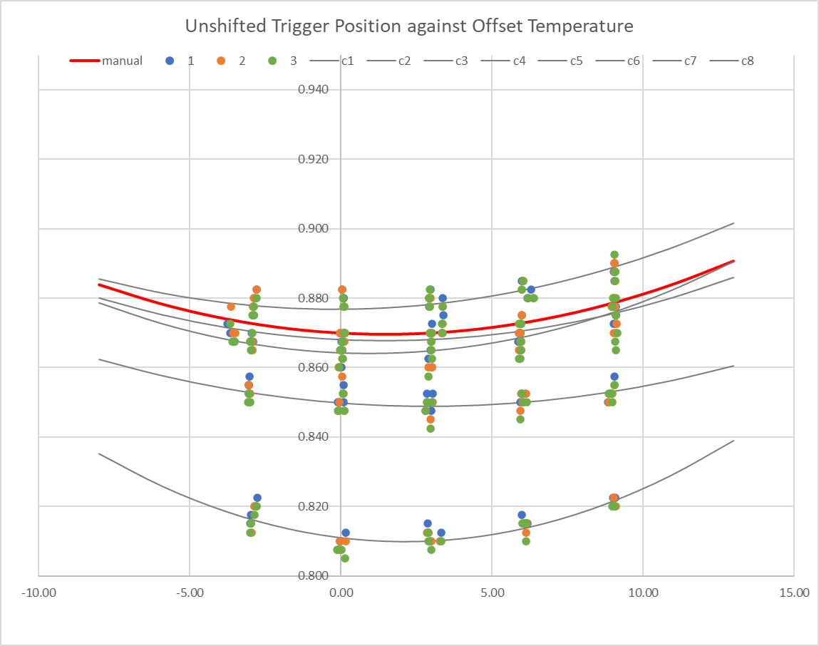
Now I get a more consistent temperature coefficient, which is distinctly non-linear, but which matches quite nicely to a 2nd order polynomial:
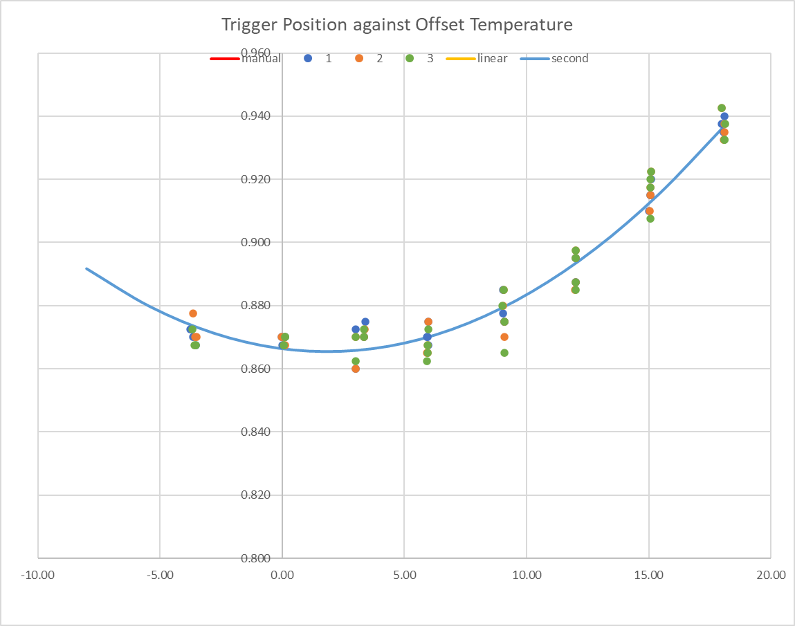
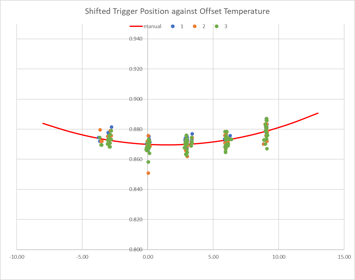
If I put multiple runs on one graph, I find that the behaviour is relatively consistent. I first discovered my printhead homing approach was not giving me a consistent result, which manifests as all the points in the test-run matching the curve relative to each other, but offset by an absolute amount up up to 0.06mm low (i.e., the homing was apparently setting up the axes too high). Therefore I have taken the data from each single test run (typically 32 bed level readings in eight sets of four readings at each temperature), fit a second order polynomial, find the shift that would bring the polynomial to my calibration point (0.87mm at 30C), then apply that shift to all the data in that test. When I do this, the resulting scatter across all the tests (five runs and counting) is about the same as the scatter within any one test, so I'm finding quite consistent response from the probe (after I fix my initial axis homing).
I'm curious how the standard firmware manages to do a calibrate in a few minutes if this time dependency exists, but possibly it doesn't actually calibrate directly, and just takes some readings that it uses to adjust the built-in calibration.
This is fairly niche information, I appreciate, but I thought I'd post in case anyone is interested. Actually, my main conclusion is that I didn’t really need to bother, because my conclusion here is that over a 15C range where I’m interested (most of my prints start with the probe at about the same temperature), the trigger height only varies by 0.01mm (ish).
From reading around on various forums, I wonder if Pinda v2 probes are possibly not only temperature-dependent but also show quite widely varying dependence – there are reports of people changing probe and suddenly finding calibrating the first layer much easier or much more difficult. Possibly I’m lucky with a low-variation one.
Even without such a (hypothesised) variation, this specific data may not be relevant to anyone else, because the apparent temperature correlation is a function of the thermistor properties (I have no idea how consistent the thermistor is), the electronics actual dependency and the behaviour of the bed (i.e., my bed likely moves differently in response to temperature than anyone else's - it's a Prusa Mk2.5 heated bed, but I've modified it a bit (notably insulated the bottom) and it's no longer on a Prusa frame).
Conclusion
So the conclusion to all that is that I've now got a calibrated 2nd order polynomial temperature compensation, but actually it's a small enough effect that I could do without. Over the range 25 to 35C (where I normally am when probing the bed at the start of a print) the compensation equates to a variation in trigger height of only 0.007mm (between max and min), or about three microsteps on the z axis.
Workings
I'm happy to share my workings (e.g. the files that run a PID loop on the bed temperature), but they aren't going to be of any use to anyone using stock Prusa firmware (or any standrad Prusa mainboard), so probably not worth posting them here. If anyone wants my data underlying the graphs above I'm happy to email it if you get in touch
RE: Pinda v2 temperature study
I would like to have the update files, I have a Prusa Mk4 2.5s machine with Super P.I.N.D.A AND Duet3 mini CARD. Thanks
RE: Pinda v2 temperature study
This was the source but it didn't work for me, the files are incomplete, and it always gives me pinda errors ect, I have written there in the comments but no one responded-
https://www.cnckitchen.com/blog/prusa-mk25s-duet-3-mini-5-conversion