RE: Oh no we're skewed! Prusa Mini edition.
Honestly I'm thinking of sending the Mini+ back. I have a XY skew which is a pain to fix and I fear will be back with time.
Really this should be fixed through software/firmware.
Yeah, It might have been smart for me to follow other designs on the labels. They don't necessarily match up with other calculators.
RE: Oh no we're skewed! Prusa Mini edition.
hello, i used goskew with prusasclicer for a mini+ and i notice in the gcode file anomalies on thumbnails after processing in goskew. i guess you have to remove the thumbnails in prusasclicer?
for example :
; generated by PrusaSlicer 2.5.0+win64 on 2023-02-03 at 12:40:34 UTC
; thumbnail begin 220x124 11772
; h786ZPQNCVG1lMaIqJq5zqTEX7.000uqFAoc78mbVY0.000DaAUcq8GzDB3nQiUnFmCvlWboX7.000uNk+paElUEX7.000Y0.000
; nspOi3VXUiQ2GToNFkuo/MtM4DDWOEyn7eQ+OaoKFqegp5Y+1jyWBj22VTboDj5rrHvYBzXVIvtdpJ
I've also noticed this, but haven't had time to fix it. As far as I've seen it doesn't effect the print, only the preview image.
I've made an issue for it, so I'll take a look when I can. Should be a pretty easy fix.
RE: Oh no we're skewed! Prusa Mini edition.
Thanks Kranex
i examine your code
I thinks two solutions
- modify regex (add space after ] ' -> gmatch, _ := regexp.MatchString(`G[0-1] `, line)
- testing the first char of each line -> for i, line := range lines {
if first char not equal ';'
gmatch, _ := regexp.MatchString(`G[0-1] `, line)
if gmatch {
blablabla
as I don't know 'go' I modified the regex and after compilation it seems fine
RE: Oh no we're skewed! Prusa Mini edition.
After playing with this for a while I came to a realization. The problem isn't skew, or at least not what Marlin calls skew. Skew is consistent. You can measure and compensate for it. The mini has what you might call 'swing'. Dial it in before a print and it will be changing with almost every layer. I ended up giving mine away; I can't use it to make mechanical or matching parts so it's no good to me. I thought about machining a couple aluminum parts to reduce the swing but even ignoring the swing I have better printers and the person I gave it to had no printer. It will do random toys downloaded from Thingiverse but beyond that it's pretty bad.
RE: Oh no we're skewed! Prusa Mini edition.
Thanks Kranex
i examine your code
I thinks two solutions
- modify regex (add space after ] ' -> gmatch, _ := regexp.MatchString(`G[0-1] `, line)
- testing the first char of each line -> for i, line := range lines {
if first char not equal ';'
gmatch, _ := regexp.MatchString(`G[0-1] `, line)
if gmatch {
blablabla
as I don't know 'go' I modified the regex and after compilation it seems fine
Fixed it in the latest version, took longer than expected as it kept slipping my mind.
In the end I decided to go with:
^\s*G[1-2]
To the best of my knowledge, at least out of a slicer, gcode is always one instruction per-line and that line always begins with the instruction.
Conditionals would be an exception to this rule, but I highly doubt that translation gcode that would require skewing would be in conditional logic.
To really do this properly I'd have to upgrade goskew to parse gcode into an AST and manipulate it that way. There's libraries for it but I don't think
it's enough of an issue to deserve the effort.
RE: Oh no we're skewed! Prusa Mini edition.
Hi
Just wondering is the XY skew generally the same on mini (printed Y front/back) mini+ (injected moulded Y front/back) ?
RE:
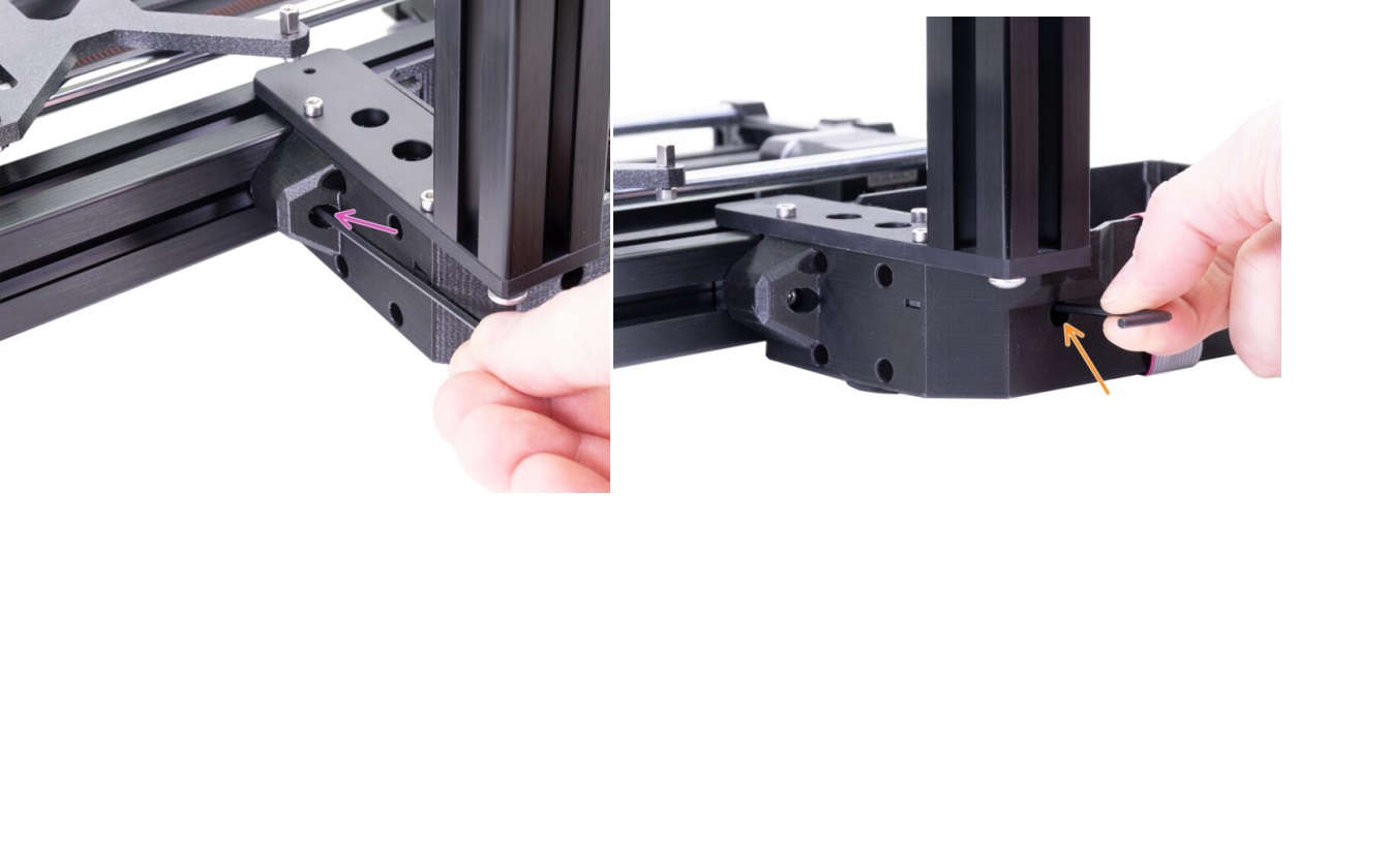
Guys I've been trying to correct my mini for months, besides making many upgrades(extruder and heat-break Bondtech) I decided to square the machine as much as possible.My mini suffers from a tilt of the XY axis, toward the board and not toward the display as usually happens(see orange arrow):

The deviation is small, and I could not correct it in any way.
Mounting the pgooch designed shims beside the buddy in my case makes the problem worse, because my axis has to be shifted counterclockwise.
The only possible way to be perfect was to screw the top screw of the box buddy to the aluminum profile:

But leave the two side screws unscrewed.
This is because screwing those screws brings the box closer to the aluminum bar and inevitably shifts the y-axis clockwise.
So however the printer becomes very unstable, I could try to print a new box buddy mo I would then have to disassemble the whole machine without the confidence to solve.
I came across this thread by chance and saw the solution created by goskew.I printed the calibration triangle and got the following measurements:
SX:99.48
DX: 99,86
Base: 99.86
I then reworked the gcode with the command:
goskew tri 99.86 99.48 99.86 -o caliangle-skewed.gcode caliangle.gcode
I printed the modified gcode and obtained the following measurements:
SX:99.76
DX: 99,76
Base: 100.00
Is it normal to get these measurements? I don't understand why the base is longer. I have the impression that the script just reversed things.
RE: Oh no we're skewed! Prusa Mini edition.
Hey guys!
I found this thread from the YouTube video and the GitHub repo.
Of course I have been suffering the same issues as all of us MINI'ers. Thanks for sharing all this it really helped me to identify that was my XZ misalignment which was making the issues.
Checking possible solutions I came across this model and this, so I decided to combine both to help myself with the calibration.
I hope it is helpful for somebody else.
RE: Oh no we're skewed! Prusa Mini edition.
Re. Carlo
my mini (printed Y front/back) had a 10% XY skew after alot of measurement, it was my Y axis (if you have a long enough Machinist Square) mine was of buy 1,1mm
so if you have the mini with the printed Y fornt/back it can be the same issue


RE: Oh no we're skewed! Prusa Mini edition.
Is there a way to account for a much larger skew?
When I check my XZ squareness, it's off by quite a lot.

The screws that hold the Z axis up on the Y axis are already tensioned so much that adding more force would probably break something, and the suggestion on the Prusa help center to re-align the righthand Y extrusion doesn't work, since the extrusion cannot rotate enough to compensate for this amount of skew.
The difference is about 4mm between the floating end of the X axis and the near end. The printer can compensate mostly, but I'd like to actually get it to be square somehow.
RE:
Sorry to necro-post a bit here. This thread has been great. I'm trying to do the silicone tube bed levelling mod to squeeze the last bit of variability out of my printer, and running into an issue with it. I may be expecting too much? But... the instructions in Prusa Mini Silicone Bed Levelling mod state to try to get the bed level within .02mm - and hopefully 0mm difference between probe points. I can't near get there at all...
It seems like (lack of) consistency in the mesh bed levelling process is thwarting my attempts. I'm wondering if I've got something wrong (maybe a bad sensor), or if I'm expecting too much precision out of the process?
Here's what I'm seeing and what I've tried to correct it!
Prior to diving into the PMSBLM, I squared the printer up again, including adjusting XY squareness, etc, following this thread. After that, I started the PMSBLM mod. I probably did about 10 mesh bed leveling processes, and fed the results into the calculator/graph generator provided by PMSBLM project (awesome project, and tooling - thank you!). I started adjusting bed level per instructions from the calculator, ran another mesh bed leveling, and repeated - until I started noticing that it had me adjusting the same fastener in opposite directions on consecutive runs, and things were getting silly.
So, I ran three mesh bed leveling runs in a row, with no changes (and ensured that nozzle temp was at 170, bed temp at 60). There were fairly widely varying differences between all three runs, with the values for a given probe location having a spread of up to .15mm (almost a full layer height). (note, that's eyeballing the data - I haven't tried to programmtically crunch it to get 100% accurate numbers - but eyeball is good enough for discussion?)
I went through several adjustments and ran three mesh bed leveling procedures in between each adjustment, trying to make things be more consistent:
- loosened trapezoidal nut tension
- No real difference in spread between readings
- Adjusted Super PINDA sensor position, per installation guide
- It turns out, I might've missed this step in assembly - I needed to come down a full "zip tie thickness" height
- Note to self - this invalidates previous stored values for Live-Z adjustment on my sheets...
- But... no real difference between readings
- Adjusted trapezoidal nut tension again - basically screw heads touching nut with no real tension
- Again, no real difference
(if it's useful, I have the output from "G29 T" gcode from each...)
Using Octoprint to talk to the serial port, and monitoring the actual height numbers reported by the firmware during sensor readings, it looks like the Z-height that's read is pretty inconsistent from reading to reading, varying by up to .06mm for a given probe location. The firmware is clearly doing some math/figuring from there to average those readings, and use that to develop the mesh bed leveling map based on that run.
Between the Super PINDA sensor readings, and the firmware decision making, I end up with a difference between each mesh bed leveling procedure of up to .14mm or so (so, again 3/4 of a layer, or so) - and that seems to be big enough to make a significant difference, possibly enough that things like Bed Leveling Correction are ineffective from print to print (Bed Leveling Correction operates in .001mm, adjust off of... mesh bed leveling?, and every time you do mesh bed leveling, it's changing each probe point by up to .14mm with no change in hardware), and that PMSBLM leveling "right" (down to .02mm or less) are basically impossible to get nailed down.
Before I go nuts... anyone got ideas about what I might be missing, or whether I might have a hardware problem (S-PINDA sensor, or...??) - or is this the precision limit of the system, and I should ignore PMSBLM's suggestion of trying to get the bed level to within .02mm?
RE: Oh no we're skewed! Prusa Mini edition.
You may be just hitting the issue of deviation in readings due to the setup not being stable due to loose parts and the fact it's all plastic that wobbles during the movements, and on that lengths of the elements it gets to the level so being really hard to avoid without additional changes. Add to it some delays in the probing movements and how it senses the plate/readings and you got the spread in the readings?
No wonder the first layer in the PrusaSlicer is 0.2mm to just smooth out most of the issues 😉
Some rabbit holes I could recommend if you really care, but frankly speaking I have no idea if it would solve your problems:
- reprint plastic parts in ABS/ASA or PC to make it more rigid (and useful if you print things in higher temps)
- bear mod - to increase rigidity even more
For me the silicone mod is not really needed, I have no issues after bed leveling, because proper squaring and MBL procedures are enough, maybe I'm super lucky with my model....
See my GitHub and printables.com for some 3d stuff that you may like.
RE: Oh no we're skewed! Prusa Mini edition.
You may be just hitting the issue of deviation in readings due to the setup not being stable due to loose parts and the fact it's all plastic that wobbles during the movements, and on that lengths of the elements it gets to the level so being really hard to avoid without additional changes. Add to it some delays in the probing movements and how it senses the plate/readings and you got the spread in the readings?
You may be right, there - just wobble in the system, or vibration. Still makes me wonder about the directions in the PMSBLM project, though - if this is "standard" performance, there's no way someone can get the bed zero'ed out as they suggest. I realize we're talking about comparatively small movements, here, of course.
No wonder the first layer in the PrusaSlicer is 0.2mm to just smooth out most of the issues 😉
Some rabbit holes I could recommend if you really care, but frankly speaking I have no idea if it would solve your problems:
- reprint plastic parts in ABS/ASA or PC to make it more rigid (and useful if you print things in higher temps)
- bear mod - to increase rigidity even moreFor me the silicone mod is not really needed, I have no issues after bed leveling, because proper squaring and MBL procedures are enough, maybe I'm super lucky with my model....
I might yank the silicone mod and go back to the original install, and see what I see there, too. If it's really not any better, I might as well roll with the stock setup with bed leveling correction set to sort of average all the readings and just go from there or something.
The bear mod looks to be more than I think is reasonable given the printer I'm working with - at some point, I'd be better off upgrading rather than fighting a lower cost design. It's definitely not a bad printer, but it obviously has some limitations vs. other designs.