Direct addressing of GPIO board
Does anyone know or have figured out the I2C address for this board?
I have a number of these (4) and would like to utilize outside of the Mk3/4/C1 environment.
Thank you...
Best Answer by Sembazuru:
Additional info for anyone interested. The chip in question is a TCA6408ARGTR, and here is the link to the datasheet on TI's website (link copied from the DigiKey product page):
That should give you all the commands. There is an ADDR pin (pin 16) that on the I/O board is tied to ground. I don't have physical access to the board to see how Prusa did it, but if there is an accessible trace that can be cut and you are able to tie that pin to the VCC of the chip (3.3VDC) then the address will change to 0x21 and you could have two of these boards on the same I2C bus without any extra chips (like an I2C multiplexer). Would have been nice for Prusa to run that pin to a jumper where the user could easily change the address to allow two I/O boards on one printer, but I don't see any indication of that on the schematic. I have a suspicion that Prusa just tied that pin to the same copper fill that the middle pad is soldered to. In that case, there would be no way of isolating pin16 without SMT rework.
RE: Direct addressing of GPIO board
So if anyone is interested, I ran a serial scanner on the GPIO board. Turns out the address is 0x20. It responds nicely to commands from a RPi.
Now to find some use for it!
RE: Direct addressing of GPIO board
Additional info for anyone interested. The chip in question is a TCA6408ARGTR, and here is the link to the datasheet on TI's website (link copied from the DigiKey product page):
That should give you all the commands. There is an ADDR pin (pin 16) that on the I/O board is tied to ground. I don't have physical access to the board to see how Prusa did it, but if there is an accessible trace that can be cut and you are able to tie that pin to the VCC of the chip (3.3VDC) then the address will change to 0x21 and you could have two of these boards on the same I2C bus without any extra chips (like an I2C multiplexer). Would have been nice for Prusa to run that pin to a jumper where the user could easily change the address to allow two I/O boards on one printer, but I don't see any indication of that on the schematic. I have a suspicion that Prusa just tied that pin to the same copper fill that the middle pad is soldered to. In that case, there would be no way of isolating pin16 without SMT rework.
See my (limited) designs on:
Printables - https://www.printables.com/@Sembazuru
Thingiverse - https://www.thingiverse.com/Sembazuru/designs
RE: Direct addressing of GPIO board
Good info - you do have one area where you can cut the trace, or sever the leg at the solder pad. Tricky but can be done. I'd load the picture but for some reason the 'add media' button doesn't work...
RE: Direct addressing of GPIO board
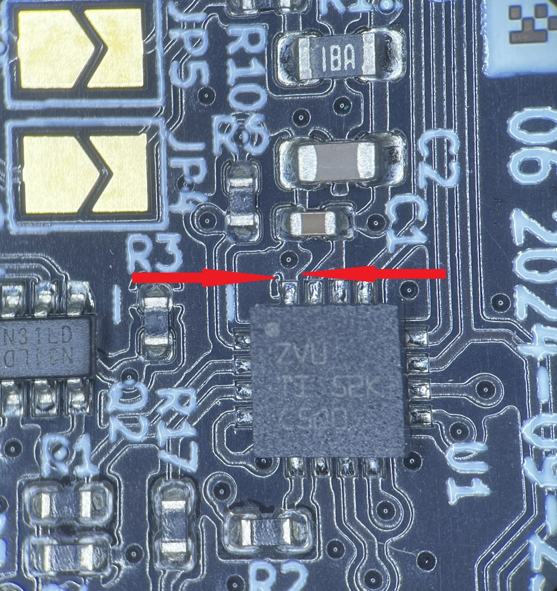
Maybe, but I think I might see a problem. It looks like that pad has at least one more connection to the copper fill on the side. I added an orange arrow to the picture pointing out what I see. To me, that looks like the spokes of a thermal relief for the pad and the one I point to with the orange looks like it goes under the body of the chip. Someone with the hot-air rework tools and a spare board to lift the chip would have to investigate further. I have neither... 🙁

See my (limited) designs on:
Printables - https://www.printables.com/@Sembazuru
Thingiverse - https://www.thingiverse.com/Sembazuru/designs
RE:
You probably need to cut it higher on the pictures - between the closer condensator and the place with a hole around the dot, and then solder the jumper cable to the second pin on the bottom left ( ground).
Using hot air to remove the chip to see underneath is important, not sure what's there - thermo pad could be connected to something like GND.
Another problem that I see is thst mentioned hole with the dot, it can go to the other side and may be important for other components. So without unsoldering the chip and checking overall layout would not risk it.
See my GitHub and printables.com for some 3d stuff that you may like.
RE: Direct addressing of GPIO board
Good point - there may be other connections (to the component above the chip) underneath. FYI - the hole is a via connecting that net to other components thru traces on the back
RE: Direct addressing of GPIO board
An i2c address multiplexer would let you use all four hackerboards without other mods. This one from Adafruit handles up to 8 same-address devices:
Using it is fairly straight-forward: the multiplexer itself is on I2C address 0x70 (but can be adjusted from 0x70 to 0x77 using jumpers on the back) and you simply write a single byte with the desired multiplexed output number to that port, and bam - any future I2C packets will get sent to that port. In theory, you could have 8 of these multiplexers on each of 0x70-0x77 addresses in order to control 64 of the same-I2C-addressed-part.
Not as satisfying as a simple trace cut, but then the trace cut wouldn't let you use all four at once...
RE: Direct addressing of GPIO board
Cute!
To every problem, there's always a clever answer out there.....