Splitting a revolved STL using a tongue-and-groove joint (plastic housing style)
Hi,
Does anyone know a way in PrusaSlicer to split an STL along a parting plane and create a tongue-and-groove (male/female) joint for alignment, similar to plastic housings?
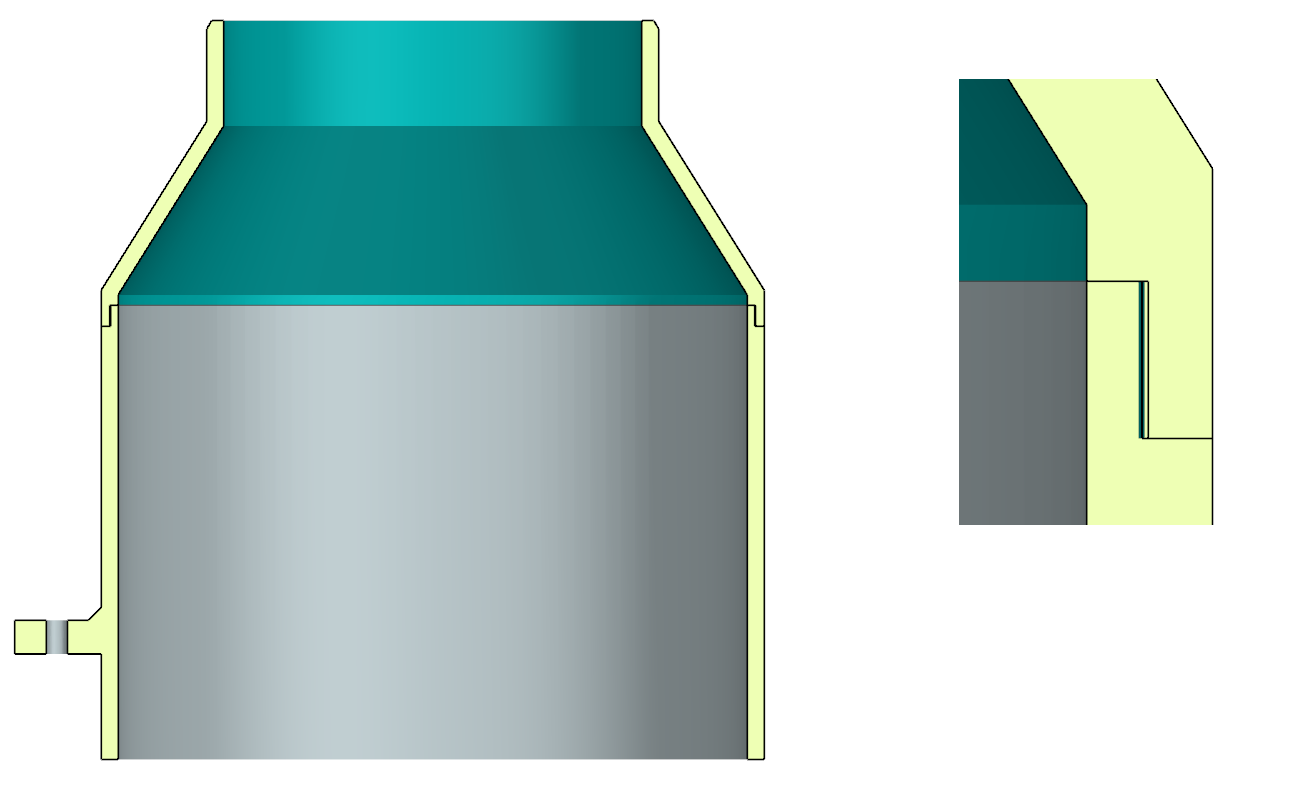
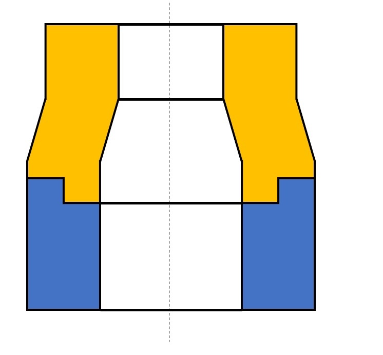
I received an STL file from a client that looks like the first image (a revolved part). To improve print quality, reduce print time, and avoid excessive supports—especially on the upper conical surface—I would like to split the part into an upper and a lower shell, as shown in the second image.
The goal is to create a self-aligning joint (tongue & groove / pilot lip) so the two halves center properly when assembled, just like injection-molded plastic housings.
Unfortunately, the file is STL-only and can no longer be edited parametrically in a CAD program, and doing this manually has proven quite tedious.
Is there a clean workflow in PrusaSlicer, or would you recommend another tool specifically for:
splitting an STL along a parting plane
adding a tongue-and-groove / locating feature
optimizing the model for FDM printing with minimal supports
Any suggestions or proven workflows would be greatly appreciated. Thanks in advance!

RE: Splitting a revolved STL using a tongue-and-groove joint (plastic housing style)
You could ask an AI to do it. Upload the STL, upload the cross-section image and ask it to split it for you. Most of the time it will give you what you want, sometimes it will produce gibberish.
Otherwise I would pull this into OpenSCAD, revolve the lower part then subtract it out.
Or, it's a pretty simple part. Can just reverse engineer it in FreeCAD, Fusion 360 etc.
RE:
I've experimented with this kind of structure for electronics cases that mimic the injection-molded off-the-shelf boxes. The devil is in the details - you'll need quite a few "fudge factors".
For a workflow, it would be a few lines in Python with FreeCAD and AI is really good to walk you through this (it makes loads of mistakes that are easily spotted trying its input, it's an iterative process).
Depending how it's meshed, the computational burden may be non-trivial. Boolean "common" operation is usually less problematic than its "cut" counterpart so the approach I'd take is to generate both an upper-side template and a lower-side template with what you want to keep, then
partA=stlImport.common(upperSideTemplate).removeSplitter()
partB=stlImport.common(lowerSideTemplate).removeSplitter()
For loading the file you can try (with "doc" an existing document)
fn = "C:/temp/3649 Medium Stone Grey Technic Gear 40 Tooth.STEP" # file name from my example
Import.insert(fn, doc.Name)
solids = []
for obj in doc.Objects: solids.extend(obj.Shape.Solids)
single_solid = solids[0]for s in solids[1:]: single_solid = single_solid.fuse(s)
stlImport = single_solid.removeSplitter()
Here is an example that resulted from fairly similar code (splitting an existing design):
https://www.printables.com/model/1497084-3649-stone-gray-lego-40-teeth-gear-with-zebra-dna
But as said, the biggest challenge are the "fudge factors" is making the two parts fit. The obvious approach would be deriving e.g. lowerSideTemplate from a suitable solid e.g. cylinder by simply subtracting upperSideTemplate. This works up to the point where you try to assemble the halves...
As @hyiger suggests, it would be relatively simple in OpenSCAD but you might approximate it in PrusaSlicer with the cut function, check 'Add Connectors' and edit the connectors to suit.
Having written that, based solely on your pictures, I see no need for supports, especially if the part is printed inverted.
Cheerio,
RE: Splitting a revolved STL using a tongue-and-groove joint (plastic housing style)
Thanks everyone for the suggestions — I really appreciate this great community.
After testing a few approaches, I ended up finding a workflow that worked very cleanly for my specific case, so I wanted to share it here in case it helps others working with STL-only files.
Because the model was provided strictly as an STL, I imported it directly into Siemens NX, which offers very robust tools for working with facet bodies.
Workflow used in NX:
Import STL as a facet body
NX allows the STL to be treated as an editable body rather than just a visual mesh.
Split the STL along a defined parting plane
I created a datum plane at the optimal split location and used Split Body to divide the part into an upper and a lower shell.
Add a tongue-and-groove (pilot) joint
Due to the very thin wall thickness (≈3 mm), traditional connectors such as pins, dowels, or screws were not viable options.
For this reason, I used a tongue-and-groove joint, which provides reliable self-alignment while maintaining uniform wall thickness and structural integrity.
Export both halves as separate STL files
Each part remains perfectly aligned during assembly and ready for printing.
Why this approach worked well:
Clean self-centering alignment during assembly
No need for fragile connectors in thin walls
Significantly reduced support material
Improved surface quality on the conical section
Faster print times and lower material usage
In my case, only the lower part requires support, while the upper section prints cleanly on its own.
While PrusaSlicer is excellent for slicing and basic cuts, for adding functional mechanical features to STL-only geometry, using a CAD system like NX proved to be the cleanest and most controllable solution.
Hopefully this helps anyone facing a similar challenge. Thanks again for all the helpful input!
RE: Splitting a revolved STL using a tongue-and-groove joint (plastic housing style)