Sequential Printing using Spiral Vase mode with Multiple Objects (15) - here's how
 Here you can see the print is nearing completion with no issues!~
 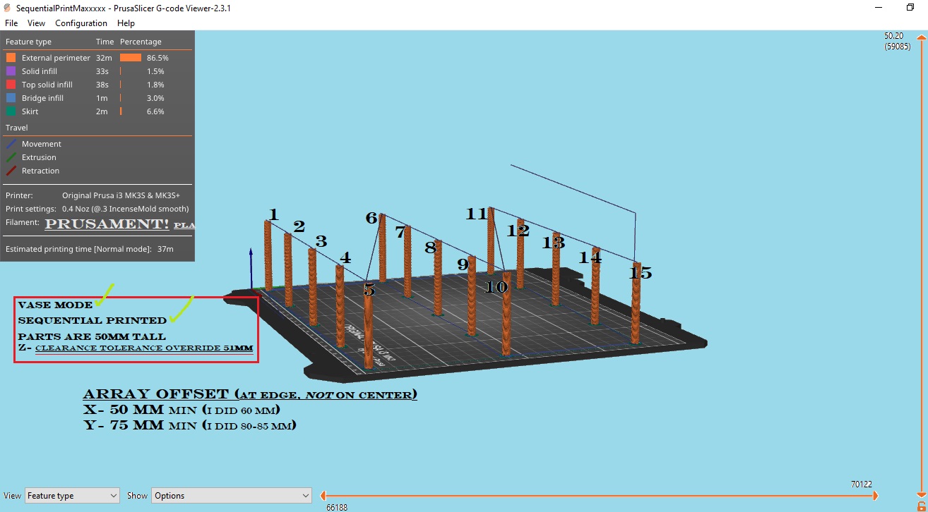 This only took 37 minutes!
(I kinda described everything already between the captions, descriptions, and text of the pictures. Any questions please feel free!)
~edit~ does anybody know why I cant see the pictures in my post?~ Do you see them?
I apologize if this is old news, I was unable to find anything regarding printing multiple parts sequentially with spiral vase enabled. I am relatively new to the forum and to printing itself, and I am only a few months into using my printer and still excited by just about everything! Please ignore that I failed to put the skirt far enough away to avoid the brims (yes the brims have been run over by the skirt)...... I was sick of getting the error of "toolpath outside of print area" during slicing, and just crammed it in there. It would probably have been better had I just translated everything a few mm to the back to make room, or simply not used a skirt. What can I say- I like a tight skirt....
I used Sequential Printing (complete individual objects), Spiral Vase Mode, .4 dia nozzle, and printed them Front Row First (Left to Right), and then printed center row (Left to Right) and finally the back row (Left to Right). This eliminates the need for *ANY consideration of Z height These parts are only 5mm diameter, and and you are only limited in total number of parts at a time by the physical X and Y sizes of your parts.* (this is not always the case, and I will explain down below). You must have a clearance in the X axis of roughly 45mm from edge to edge so do take into account the part dimension itself....not the center point! In Slic3r it says 42mm I believe, and that is probably accurate but the truth is unless you are printing a 1mm wide part, you need to calculate each part from its X-axis-edge to the edge of the next part on the X axis, in order that it does not get touched by your extruder FAN. If it's even too close at a height of 20+mm and not cooled, it could theoretically get sucked into the fan. Stringing would also get sucked in, but we dont have to worry about that....spiral vase....
The Y axis clearance is a little bit more tricky if you are trying to maximize your number of parts, for several reasons. Firstly, some of this only applies *if your parts which are higher than 20mm are also small enough (in the Y dimension) so that the lower X-axis rod does not ever "travel far enough in the Y axis" (in reality it is the bed moving and not the x-axis rod) that it crosses the other parts (which are along the X-axis in relation to each other). This condition is true if the total Y length of the individual parts (if they are identical) is smaller than the distance between the X-axis rods and extruder nozzle, otherwise you must offset each subsequent part in that row incrimentally by a Y-value of [Part.Size-in-Y-dimension] minus [distance between X-axis Rod and Extruder nozzle]. It's actually much more easier than it sounds, I promise. If that was confusing, think of it this way: the parts shown here are only 5mm diameter, which is smaller than the distance between the nozzle itself and the X-axis rods. This means, at every point in travel while extruding the next part in that row, the X-axis rods never are directly above any of the parts in that row since they are fix-positioned further towards the back of the bed in relation to the nozzle, which ultimately means these parts can be unlimited Z height. When placing parts in a row which are not identical instances, it's slightly more complicated but uses the exact same reasoning to determine the offset. Next we consider the part fan, which is at an angle (which means if you have short parts you can get away with them being even closer together!) Parts under 20mm in Z means you can have parts that are very large in both the X-dimension and also the Y-dimension *untested. I think I will make a print after posting this, which will consist of 4 spiral vase which take up the entire print bed- one per quadrant- to test this. If your parts are tall enough to contact the part fan, then you will want to make sure that the outside edges of the parts in the Y column have enough distance between them that they will not come in contact with the fan when printing the next row. (It appears to be roughly 2.5 inches, so 63mm might be enough to physically clear but could get sucked into part fan if too close) I printed 50mm tall parts so that I would know they were spaced adequately (therefore I could do this same print setup with 150mm tall parts and it would be no different outcome in terms of collision). Print Order Going Left to Right= this means you don't have to consider the super pinda wiring or right side of the part fan (which sticks out), but rather only have to calculate based on the left side of the extruder -with no wiring (only the vertical fan which is a nice perpendicular to our print bed). Print Order Going Front to Back= this means you don't have to consider the wires connecting to the back of the extruder (they might be closer to print bed) since there are never any printed parts "behind you". Also, you don't ever cross any parts which have already been printed because you never return to the front of the print bed.
Hopefully this helps, is understandable enough, and the math wasn't done incorrectly. It's entirely possible that I explained something wrong, and I would appreciate if anybody points out something which doesn't seem to be correct. This does work, at least for parts of these dimensions, and so if anybody wants to explore different parts with this concept I would be happy to brainstorm if necessary. I have used this spacing method (minus spiral vase) to sequentially print out "tiny disc golf baskets"- which consist of 12 total parts (each basket was chopped into 3 pieces to eliminate supports), and if they were geometrically optimized to allow for spiral vase mode on each individual part they could also be printed with both sequential and spiral vase enabled. Just to give you an idea of how this can work for more than just tiny cylinders. I'm gonna go ahead and say it before it's proven to be true: If it can be spiral vase printed, it can also always be sequentially printed (unless it measures over half of the print bed). The same does not hold true in reverse, for obvious reasons (ie not every part is a candidate for spiral vase).
"I don't always print using spiral vase mode enabled, but when I do, I prefer to print multiple instances sequentially."
I am Egg. Keep on printing.
Pictures were too big (I think)
Here's the pictures I meant to include in my original post.
RE: Save this somewhere!
Nice write-up. I've seen this technique before, but you did a good job with providing detail. You should save it for posterity on HackADay or some such site. It would also be a good starting point for a Knowledgebase article. I'd be happy to host it for you on my pages if you like.
Thanks for that~
I'm happy to hear that you enjoyed this. I should probably do a more technical and structured job of setting it up, taking pictures of the settings, and all that before asking you to host it, but that sounds awesome if you would want to do that for me! I had all the pics and numbers ready to go before printing it (was originally doing 20 parts), except it kept failing at first layer right away and I couldnt figure out why. It ended up being the fact that I was due for my very first acetone cleaning of the bed......isopropyl 91 has been working great, but I guess ive finally broken the thing in with enough hours....so by the time I figured that out and was getting good first layers I had already changed everything and was only using 15 parts and forgot to take all the pictures and screenshots....which is why I had to settle for pictures near the end of the actual print and a screenshot of the exported g-code tool path.......woops! I would be happy to do a better job, including the exact numbers involved. I would have redone it all today before posting but I wanted to put this up because I didn't know how much info was floating around easily accessible and this changed my life already. I wish I'd known this when I was printing my backflow incense molds.......one...at....a....time....
RE: Another Incense Mold Print

Video of This Print I make my own incense, and I use molds to shape and compress them. As you might have guessed, I use Spiral Vase mode, and I also enable Sequential Printing mode. Here's another perfect example of using spiral vase + sequential printing for an actual purpose (other than proof of concept which my original was). I believe I was using 0.1mm or 0.15mm layer height for these, so Spiral Vase really saved me some time there. Hope this helps or is at least entertaining!