Part of my STL file object vanishes when sliced
(I have images in this post, but it looks like they are trimmed by the forum software, since the full width of the images is not visible in the editor. Also, I'm linking to files for Blender, PrusaSlicer, and 2 STL files. Is there a preferred way to include such files on this forum - and a way to be sure my full images are shown?)
I'm using Blender for design work and have created a handle and camera mount for an Ender 3 Pro. Here's the parts I designed, in Blender:
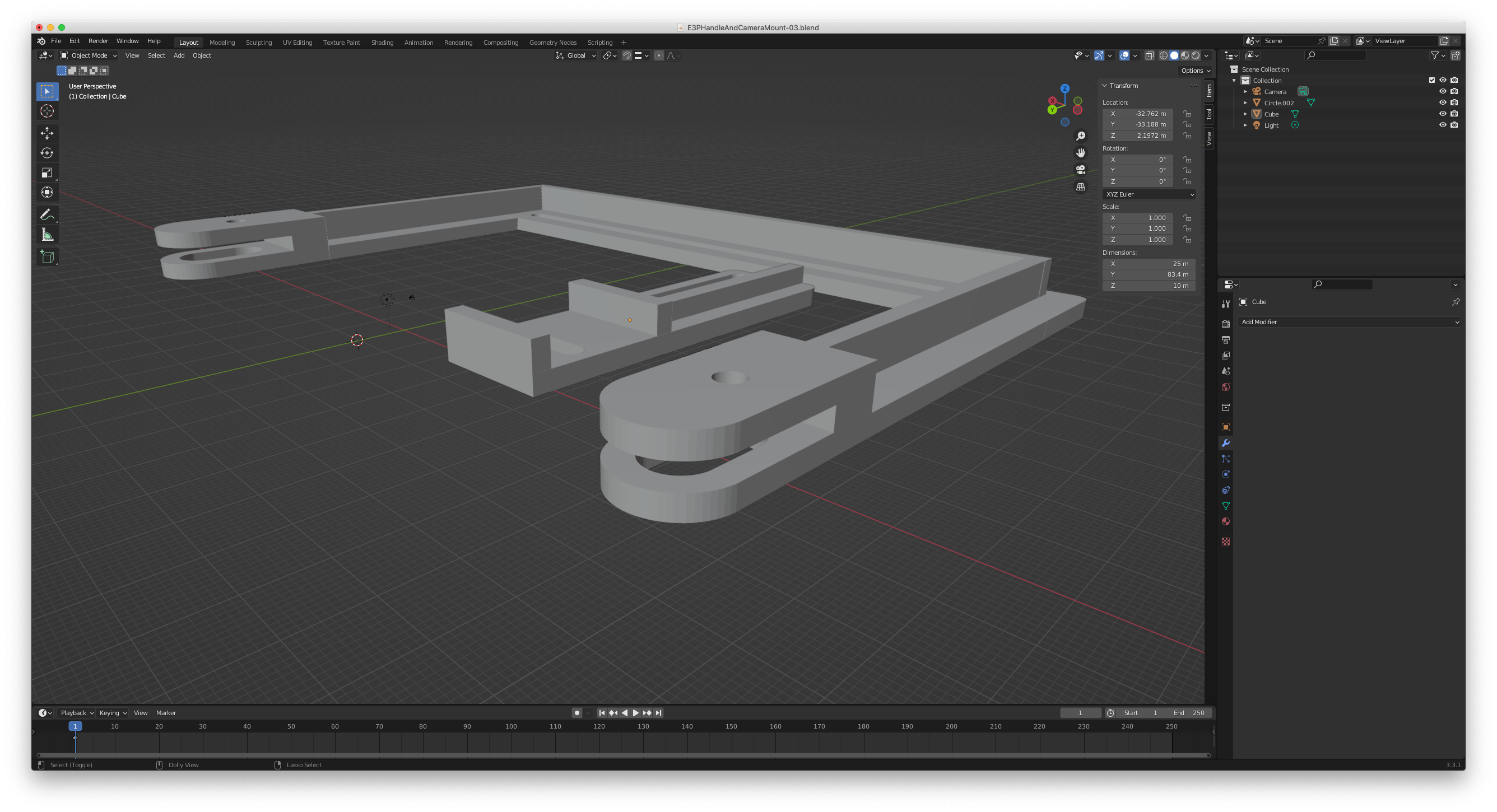
In the wider image I uploaded, you can see the full "C" shaped main object. Note that at the ends there is an upper and lower tine for the connector. You can still see this in PrusaSlicer:
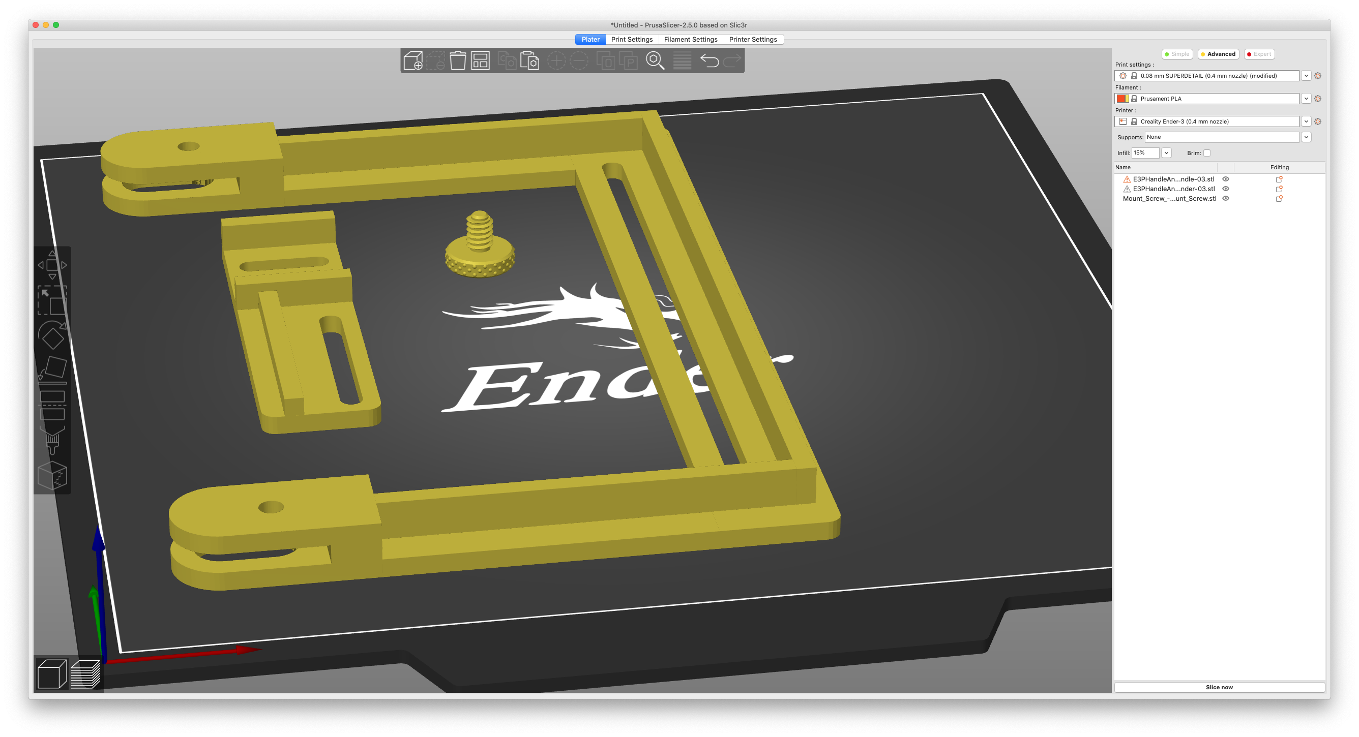
Here it is in Prusa Slicer. (The thumb bolt is from someone else - not really part of the issue). In the front bottom of the image, you can see the two tines on one end of the handle. (I'm guessing that when this posts, clicking on the image, which is cut off on the left side here, will show a full image?)
But then I slice it: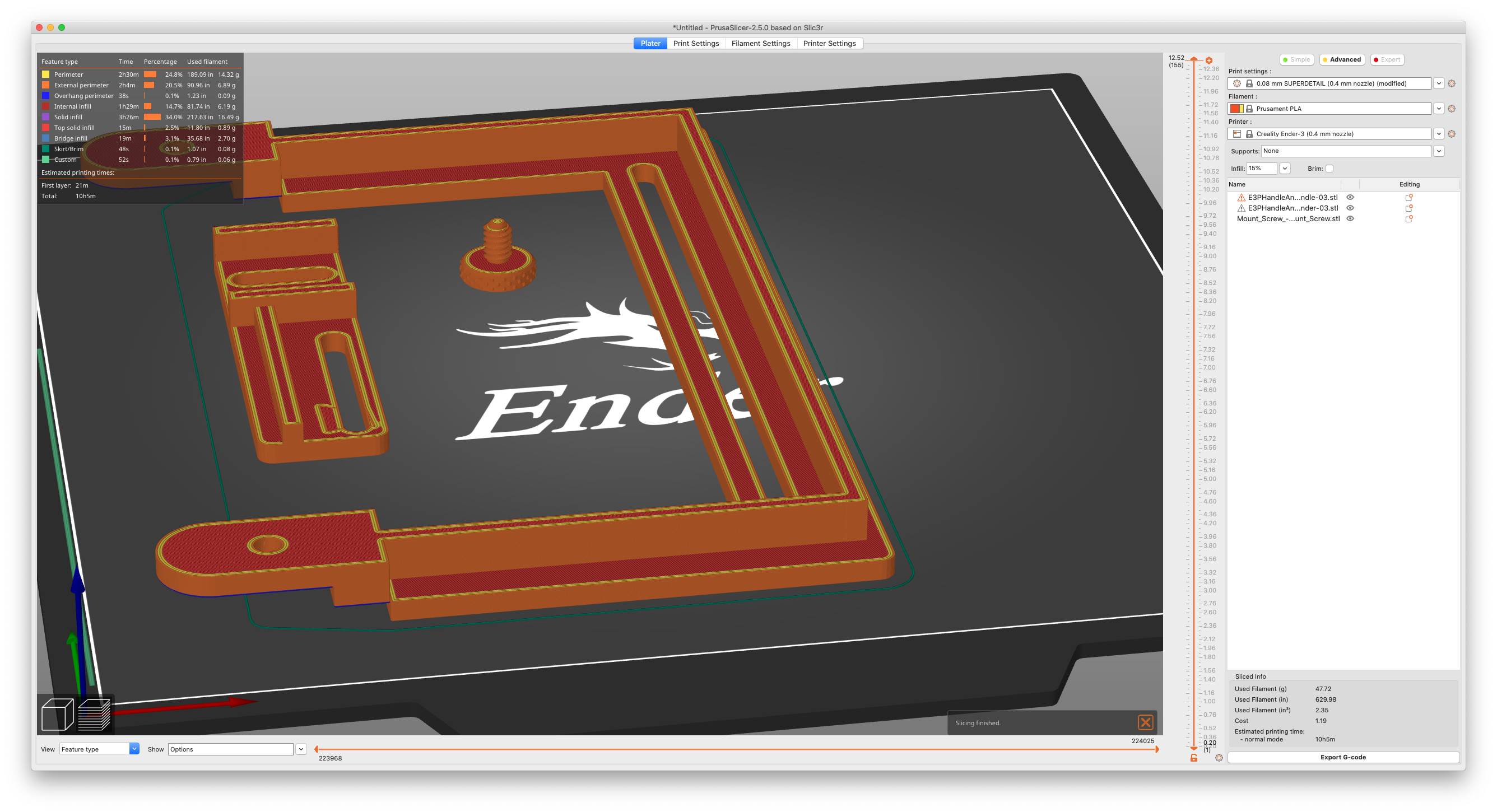
And now the bottom tine on both connecting ends is gone. Also note on the smaller mount part, the rectangular part on the left, that around the long oval hole in it, there are artifacts that don't show up in the other images.
So when I actually slice these parts, some sections of an item disappear and I get artifacts in another.
What do I need to do to take care of this?
For reference, here is the original .blend file for Blender. Also, here is the STL file for the larger part of the handle, and here is the STL file for the smaller rectangular mounting block of the handle and mount. Also, here is the file from PrusaSlicer, with just the objects in it, but not yet sliced.
RE: Part of my STL file object vanishes when sliced
When I opened your .3mf file in Slicer, it showed some errors within your objects (open edges). You'll notice the little warning triangle icon next to these objects.
I could reproduce the behaviour you described.
Right-clicking on the object and selecting "Repair through NetFabb" rendered them flawlessly and as far as I could see, slicing went fine from then on.
That "Repair through Netfabb" may not always take care of every problem, but is usually a good starting point when handling 'strange' models.
Regards,
Mike
RE: Part of my STL file object vanishes when sliced
When I opened your .3mf file in Slicer, it showed some errors within your objects (open edges). You'll notice the little warning triangle icon next to these objects.
I could reproduce the behaviour you described.
Good - glad it's reproducible! Is there a better way to include files like this with a post than putting them on file.io and linking to them?
Right-clicking on the object and selecting "Repair through NetFabb" rendered them flawlessly and as far as I could see, slicing went fine from then on.
Still learning so I didn't know about that. Thank you!
That "Repair through Netfabb" may not always take care of every problem, but is usually a good starting point when handling 'strange' models.
Obviously I'm doing something wrong. I'm still rather new to 3D and learning a lot. While I know people prefer other programs, I do want to make sure I can use Blender. I've done one or two simple, and I mean simple, project in Blender that I was able to print out and use as plans for building permits. But these were also different than doing 3D printing. For instance, one was a deck, so that was best done by creating the 8x8 posts and the 5/4" deck boards and just putting them in place through duplicating or offsetting and so on. But with 3D printing, it means creating a more complex object (like in the examples). I do see some artifacts that show up in Blender in this object, so this tells me I have to learn more. I'm extruding objects, extending them my moving vertices, and then having to add other objects that I join. I don't know if there's a better way to build things. There either is or there are corrections to what I'm doing.
It did occur to me that, like making molds for slip in pottery, or for poured metal, I could make a large block, use the original shape as a binary modifier to create a mold, then use the mold as a modifier for another block and that might give me a simpler topology, but I'm betting it's easier to just do it right in the first place.
RE: Part of my STL file object vanishes when sliced
Well, this is quite frustrating!
It appears that "Repair through netfab" is only available on Windows systems. I'm using Mac and Linux, so that rules that out for my situation. There are other options I'm looking into.
RE:
New File Links:
I did not realize file.io allows files to be shared one time and deletes them, so these are replacement links to the files. (Apparently, on this forum, editing a submitted post can't be done - or am I missing something?)
- This is the original Blend file
- This is the STL file for the larger handle object
- This is the STL file for the smaller rectangular mount
- This is the PrusaSlicer 3MF file, in case it helps. (I did get a suggestion to try to fix through netfab, but I'm on Mac and Linux, and that option is only available on Windows.)
RE: Part of my STL file object vanishes when sliced
Quick solution for the last problem: zip your files and attach the .zip file here.
I hadn't been aware of netfabb not being available for non-Windows systems. Therer are some alternatives, unfortunately most of these are Windows only, too. Microsoft seems to have retired their online services and Meshmixer, which was avaliable for Mac, has been removed a while ago.
Fusion360 should be able to access the netfabb services, maybe repairing files that way could help.
It might also be a good idea to have a look at Blender's STL-export settings. I'm not that much into Blender, but know about the problem, from almost every CAD solution I've ever used.
Maybe you get some hints from here: https://blog.prusa3d.com/repair-3d-models-errors_7529/ (but solution seem quite Windows-biased, too)
Mike
RE:
As you are using Blender then try using its 3dprint tool to run analysis on your models to find the problem areas and fix them and stop outputting invalid geometry in the first place.
For example it shows the following errors on that part of the design to have 150 Non manifold edges (which are what really kills a slicer), 112 bad contiguous edges, 105 intersecting faces, 2 zero edges, 19 non flat faces, 36 thin faces and 14 sharp edges. Most wont cause PS a problem but the non manifold will.
Also generally with debugging issue all that is really needed is the prusa slicer generated .3mf project file. As that contains all the settings you are using and the model too.
RE: Part of my STL file object vanishes when sliced
Damn ran out of edit time.
You need to go back to basics and learn about creating proper geometry. You cant just plonk down shapes next to each other and expect it to be valid for 3d print purposes.
You also might want to watch some youtube tutorials on non destructive modelling workflows in Blender. It makes designing and tweaking so much easier.
To be honest it would take less time to reproduce those parts properly from scratch than it would to try and 'fix' them given all the problems they have.
RE:
For all intent and purposes, Netfabb is basically dead as a free tool. Why it still works in the Windows version of Prusaslicer, I don't know.
With the death of Microsoft's online STL fixing tool, the one I've been using on Mac lately is https://www.formware.co/onlinestlrepair
Fast and efficient.
Formerly known on this forum as @fuchsr -- https://foxrun3d.com/
RE: Part of my STL file object vanishes when sliced
Here you go, should be a zip attached with an updated blend file you can open and examine some remodelled parts. Also included the exported stl generated from the new models.
The blend contains non destructive modifiers such as booleans and mirrors so its very easy to move/resize/ all the slots etc. They are marked as non rendered and also non visible but you can enable visibility to see how they work. If you have any questions then please ask.
RE: Part of my STL file object vanishes when sliced
Quick solution for the last problem: zip your files and attach the .zip file here.
Okay, easy enough. Thanks!
I hadn't been aware of netfabb not being available for non-Windows systems. Therer are some alternatives, unfortunately most of these are Windows only, too. Microsoft seems to have retired their online services and Meshmixer, which was avaliable for Mac, has been removed a while ago.
Fusion360 should be able to access the netfabb services, maybe repairing files that way could help.
At some point I need to download Fusion 360. For reasons I don't want to go into, I'm using Blender, but lots of times there are functions in other programs that make it worth having them even if they are not a primary too.
It might also be a good idea to have a look at Blender's STL-export settings. I'm not that much into Blender, but know about the problem, from almost every CAD solution I've ever used.
Good. Another place I can look. I know I'm new and know very little so new avenues to look into always helps.
As you are using Blender then try using its 3dprint tool to run analysis on your models to find the problem areas and fix them and stop outputting invalid geometry in the first place.
Cool. I didn't even know they had a 3DPrint tool!
For example it shows the following errors on that part of the design to have 150 Non manifold edges (which are what really kills a slicer), 112 bad contiguous edges, 105 intersecting faces, 2 zero edges, 19 non flat faces, 36 thin faces and 14 sharp edges. Most wont cause PS a problem but the non manifold will.
Also generally with debugging issue all that is really needed is the prusa slicer generated .3mf project file. As that contains all the settings you are using and the model too.
I've been doing other research and I'm finding out just how those issues are killing what I'm doing. I thought just using Join would do all that was needed and what I've learned in the past 12-16 hours is that after joining, I often still need to do a fair amount of work. I've seen someone suggesting to use a boolean modifier to join two objects and that sometimes that works very well, but sometimes it doesn't. So I can always try that and, if it doesn't work, just undo it.
You need to go back to basics and learn about creating proper geometry. You cant just plonk down shapes next to each other and expect it to be valid for 3d print purposes.
You also might want to watch some youtube tutorials on non destructive modelling workflows in Blender. It makes designing and tweaking so much easier.
To be honest it would take less time to reproduce those parts properly from scratch than it would to try and 'fix' them given all the problems they have.
I'm working on it - found a few good suggestions since I posted here. I did recreate one of the objects from scratch, a lot of it by using boolean modifiers, but I see there's a lot more to learn about building objects.
For all intent and purposes, Netfabb is basically dead as a free tool. Why it still works in the Windows version of Prusaslicer, I don't know.
With the death of Microsoft's online STL fixing tool, the one I've been using on Mac lately is https://www.formware.co/onlinestlrepair
Fast and efficient.
Thanks! I'll be exploring that.
Here you go, should be a zip attached with an updated blend file you can open and examine some remodelled parts. Also included the exported stl generated from the new models.
The blend contains non destructive modifiers such as booleans and mirrors so its very easy to move/resize/ all the slots etc. They are marked as non rendered and also non visible but you can enable visibility to see how they work. If you have any questions then please ask.
The biggest help this will be, for me, is not just that it gives me a good object to use, but that I can use it to go through and study what you've done. Thank you!
RE: Part of my STL file object vanishes when sliced
I have not yet had time to go through and look at @fuchsr's file (thank you for making a fixed version), but I find this interesting. I've been slicing to print this on an Ender 3 Pro. I made some changes and loaded it in to PrusaSlicer as an STL and sliced just that one object. Then I realized I had it set for my Prusa and not the Ender. Here's what I got:

Accepting that I have not produced a perfect STL file and that there are mistakes, I'd still like an idea why it shows up like this when sliced for my Prusa i3 MK3S+, but I still get the same issue when I slice it for my Ender 3 Pro. I tried slicing for both with my newer STL file. Here it is for the Ender:
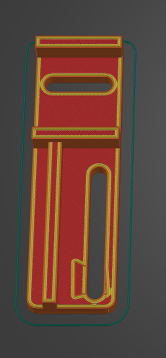
So the glitches still show when slicing for the Ender 3 Pro, but are gone when slicing for the Prusa.
I know these things can be quirky, but I also realize this is the kind of thing that could come up with other objects and situations. Why is there a difference like this depending on which printer I slice for?
RE: Part of my STL file object vanishes when sliced
I deserve no credit (or blame…). Neophyl was the one who created a fixed version. I couldn't—every time I open Blender, my head explodes 🙂
Formerly known on this forum as @fuchsr -- https://foxrun3d.com/
RE: Part of my STL file object vanishes when sliced
The surface artefacts are down to the verts around that surface being at slightly different layer heights. Theres a few around the slot fractionally lower. As the slicer is creating layers some fall slightly one side than the other and so the layer is lower. Your Ender profile has layer height of 0.08 (which is crazy thin to print at for functional parts like these) while a standard mk3 one wont have that layer height set.
If you change the layer height on the prusa and slice you will see the same issue. Theres a FAQ about it on the PS github. https://github.com/prusa3d/PrusaSlicer/wiki/Frequently-Asked-Questions-(FAQ) - the strange patterns on flat surfaces entry.
Easy enough to fix in Blender though.
I don't consider myself anything like an expert at Blender as I really only know a bit about the modelling parts, haven't touched and of the rendering or animation side, just the make models and fix models from the web needed for 3d print use. But I am quite happy to share anything I have picked up. That was one reason I included a blend file with the redone parts in so you could have a look at what I did.
The 2 objects started off as the good old simple cube mesh 🙂
RE: Part of my STL file object vanishes when sliced
Just realised saying that the irregular top surface is easy enough to fix in blender doesn't really help you does it 🙂
So here's a run down of how to do it using your original blend as a starting point.
First off I had to adjust your units. You have them set to Meters which for 3d print is not great. On the right hand side menu there is a bunch of option panels. You want Scene>Units. Its already set to Metric but change the Length to Millimeters. Then change the unit scale to 0.001000. Now everything in your layout window will be in mm. So if you create a 20mm cube and output it, it will be 20mm. Its much easier to work in the smaller units and will match your bed expectations more easily.
So select your small Object (called Cube), I believe its the actual Camera mount ? Then press the "/" on your number pad (I'm really really hoping you have a number pad on your keyboard lol). "/" basically focuses on the part(s) you currently have selected, hiding the rest so they aren't in the way. Pressing it again comes out of this mode and shows everything again.
Now press "3" on the number pad to go into a side view. Change your view to Wireframe. Now go into Edit mode ( pressing "tab" goes into and out of edit mode).
Make sure you are in Vertex Select mode (rather than line or face select). You can now use the drag select to drag a box over all the verts that make up that surface.
Because you are in wireframe mode you will select the ones behind too that would otherwise be hidden if you were in Solid mode.
You can rotate around if needed to check that you have all of them on that level selected. And you need them ALL that you want to be at the same level position.
Ok, with them selected press "S" followed by "Z", followed by "0" and then "Return/Enter". What that is doing is is is Scaling the verts, in only the Z axis by Zero, so SZ0<return>. In effect its just aligned them in the Z plane. You can align them in the other planes by using X or Y but if you do that with the selected ones it will really mess things up 🙂
And that's it. If you export the camera mount again and load it in next to your original and slice you should see no surface artefacts.
RE: Part of my STL file object vanishes when sliced
The surface artefacts are down to the verts around that surface being at slightly different layer heights. Theres a few around the slot fractionally lower. As the slicer is creating layers some fall slightly one side than the other and so the layer is lower. Your Ender profile has layer height of 0.08 (which is crazy thin to print at for functional parts like these) while a standard mk3 one wont have that layer height set.
If you change the layer height on the prusa and slice you will see the same issue. Theres a FAQ about it on the PS github. https://github.com/prusa3d/PrusaSlicer/wiki/Frequently-Asked-Questions-(FAQ) - the strange patterns on flat surfaces entry.
I rebuilt the two objects in this file in Blender to fix things and to figure out how to do it right without creating an issue. While doing that I learned about using snap and used that to line up some boolean modifiers and anything I joined to other objects. So I think you're touching on what I've just learned. I'm not going to align anything visually now. I'll do it by snapping or by actual coordinates so I get exact alignments.
I would have never thought that would be the issue - such a small difference and how that interacts with the layer height on the different printers.
First off I had to adjust your units. You have them set to Meters which for 3d print is not great. On the right hand side menu there is a bunch of option panels. You want Scene>Units. Its already set to Metric but change the Length to Millimeters. Then change the unit scale to 0.001000. Now everything in your layout window will be in mm. So if you create a 20mm cube and output it, it will be 20mm. Its much easier to work in the smaller units and will match your bed expectations more easily.
I've found that frustrating. When I get a good STL from a print site and load it into Blender, it always defaults to meters, not millimeters. I knew there's a setting I need to adjust for that - just hadn't had time to look for it. (Amazing how, until you know a program, it can be a pain to find just one simple setting!) For now, with Covid-fog in my brain (and serious exhaustion from that), I've been just keeping track that a meter in those files is a millimeter elsewhere. I'll make that change. Will the files I've been working with that are in meters adapt to that?
So select your small Object (called Cube), I believe its the actual Camera mount ? Then press the "/" on your number pad (I'm really really hoping you have a number pad on your keyboard lol). "/" basically focuses on the part(s) you currently have selected, hiding the rest so they aren't in the way. Pressing it again comes out of this mode and shows everything again.
Now press "3" on the number pad to go into a side view. Change your view to Wireframe. Now go into Edit mode ( pressing "tab" goes into and out of edit mode).
Make sure you are in Vertex Select mode (rather than line or face select). You can now use the drag select to drag a box over all the verts that make up that surface.
Because you are in wireframe mode you will select the ones behind too that would otherwise be hidden if you were in Solid mode.
You can rotate around if needed to check that you have all of them on that level selected. And you need them ALL that you want to be at the same level position.Ok, with them selected press "S" followed by "Z", followed by "0" and then "Return/Enter". What that is doing is is is Scaling the verts, in only the Z axis by Zero, so SZ0<return>. In effect its just aligned them in the Z plane. You can align them in the other planes by using X or Y but if you do that with the selected ones it will really mess things up 🙂
And that's it. If you export the camera mount again and load it in next to your original and slice you should see no surface artefacts.
Okay, got a lot of this. I've been learning to use X-Ray mode a lot. With Alt-Z, toggling between it makes selection easier, so I can select the visible or the vertices behind what I'm doing to, as needed.
I had not learned how to fix them with scaling, so that's a useful trick to learn!
While I did "cheat" and rebuild the mount from scratch, I did want to know what was going on and how to fix it - since I'm sure at some point I'll run into the same issue again. Fixing it by rebuilding from scratch is simple, but I think it's important to learn how to fix the issues directly, since you can be sure they'll show up again!
By the way, on the rebuild, I started with a cube, stretched it to a long rectangular prism, then used other edited cubes as boolean modifiers to cut out what I needed to to get the support rails and made oval boolean modifiers to get the oval holes. It was much easier to do that this time because I had the original object as a guide.