Designing and Printing Interlocking Parts - First time - advice, please?
I am printing two parts that I want to be able to fit together. Here's the male and female parts of the connector:
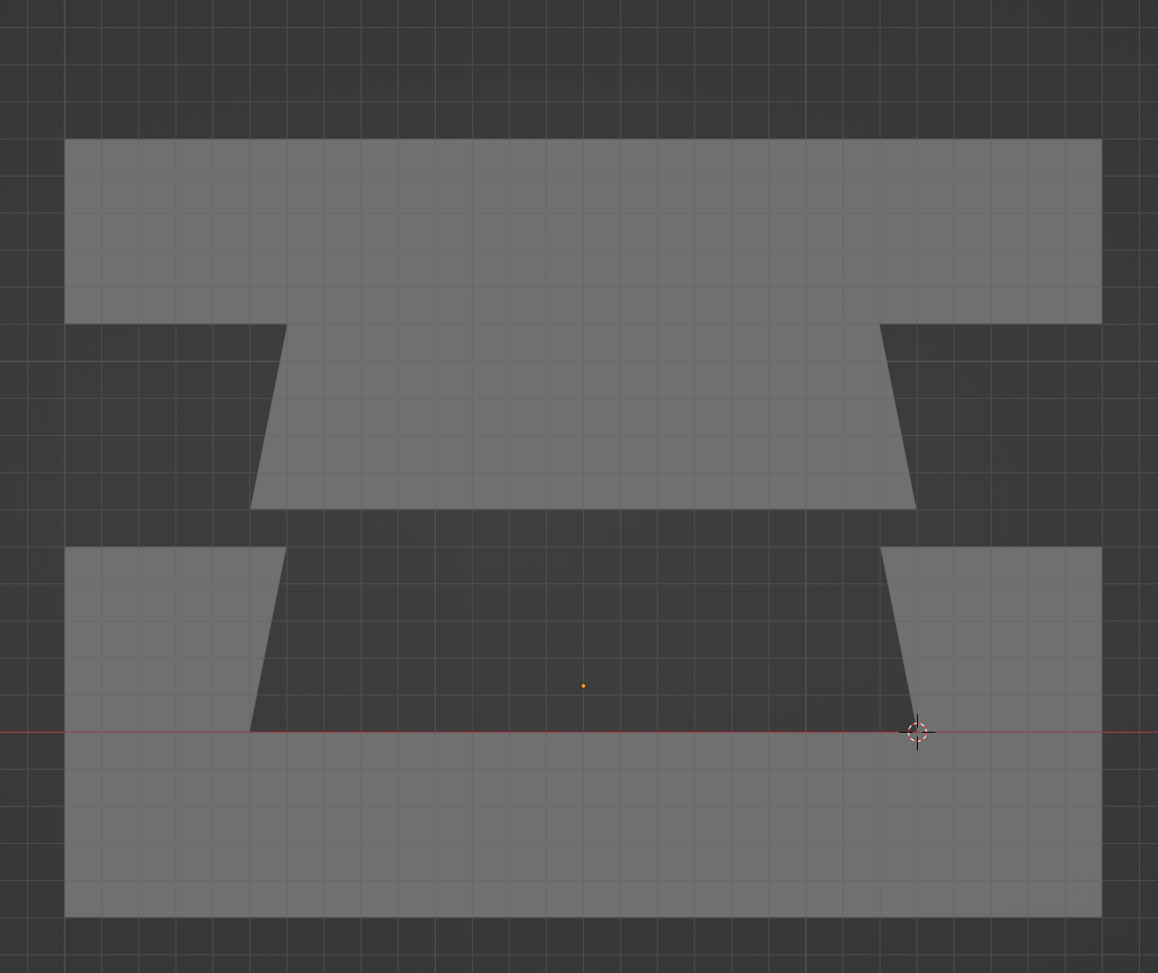
This is just a cross section of the two parts.
As it shown here, the two parts, in virtual space (in the 3D program) are exactly the same size. I was going to make up several versions of the joiner with the size of insert on the male part a bit smaller in scale in each test piece. Then I was going to take the one that gave me a tight fit and use the scaling and measurements from that test for the final print.
I'm also aware, as I look through Printables, that, in the long run, my design might be worth uploading on my account there, so I want to work with something that will likely work on other peoples' printers as well. (At least on other Prusa printers, but, in general, on most other printers.) Also, I might use this to slide the two parts together vertically. If so, I would add a bottom section so the male can't just slide out of the female during use. It's also possible I may set it up so this joint would be horizontal (imagine it rotated 90° in either direction). The scale is 1 square = 1 mm.
For those that have done this kind of thing one or more times, what advice can you offer me about designing and printing joining parts like this?
This is on the small size for a sliding fit but it should be OK. You will need to allow somewhere between 0.5 and 1 mm tolerance on the joint. If you want to prevent drop-through then making the whole joint tapered is an option.
Cheerio,
RE: Designing and Printing Interlocking Parts - First time - advice, please?
I've found that the only way to design and print such things is trial and error.
Also, keep things consistent, as in do not change filament type, infill percentage, or about any parameter between iterations, just the dimensions.
RE: Designing and Printing Interlocking Parts - First time - advice, please?
This is on the small size for a sliding fit but it should be OK. You will need to allow somewhere between 0.5 and 1 mm tolerance on the joint.
Good. Numbers like that help!
If you want to prevent drop-through then making the whole joint tapered is an option.
I considered tapered, but that might lead to issues with it not always going all the way down, so I decided I'll add a bottom on the female end so it'll stop at the same place every time.
I've found that the only way to design and print such things is trial and error.
Okay - figured on that, but nice to know it's not just me, that even the experienced people here need to do that!
Also, keep things consistent, as in do not change filament type, infill percentage, or about any parameter between iterations, just the dimensions.
Good point - I wasn't even thinking of infill as an issue, but that makes it clear to me how much anything can be a problem.
RE: Designing and Printing Interlocking Parts - First time - advice, please?
This is on the small size for a sliding fit but it should be OK. You will need to allow somewhere between 0.5 and 1 mm tolerance on the joint.
Doing more with that now. I can see what you mean. Compared to the size of the connector, a 1mm tolerance is rather large, so I have to think about that. Considering size, I may opt for only right angles instead of that slanted angle. It give me more control that way. But I definitely have to make this bigger to allow for that much of a tolerance.
RE:
I am not an expert by any stretch of the imagination, but I have one for me fail-safe method:
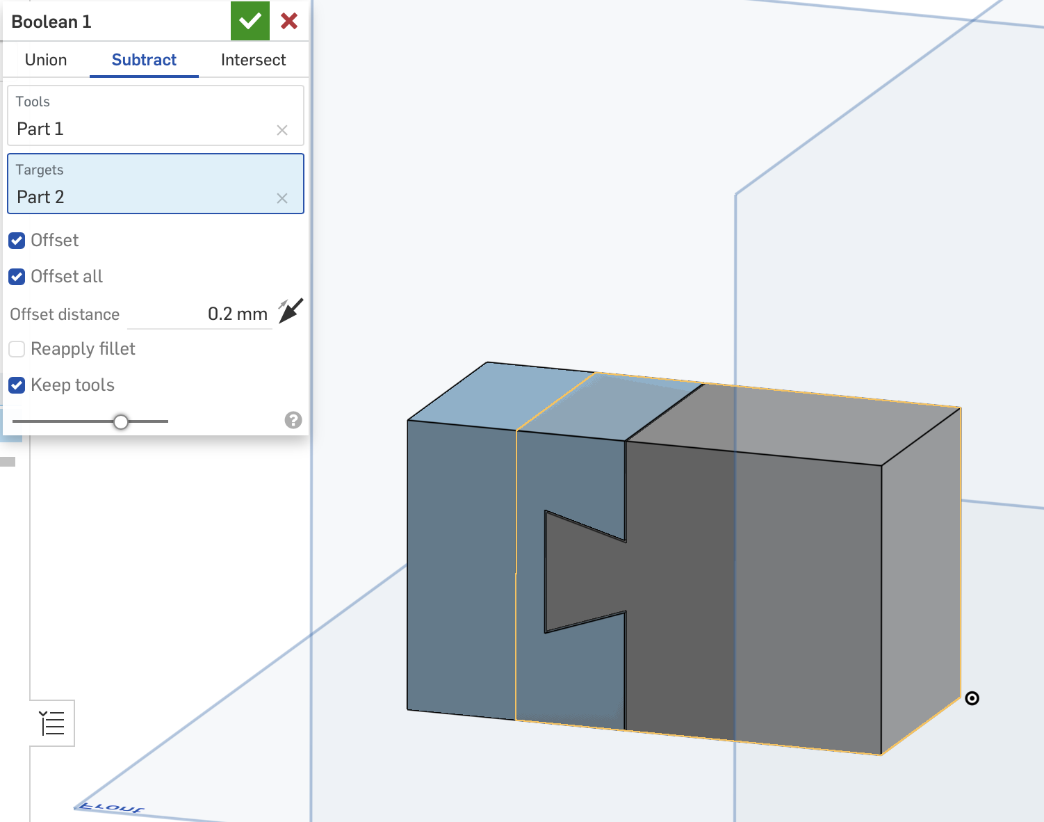
I simply draw one side of the joint, then instead of trying to draw something with all the tolerances necessary, I draw the other side as a blank shape with the overlapping part bigger than it needs to be in every dimension. Then I use a boolean subtract with a 0.2mm offset all round. This gives a tight joint with 0.4mm total tolerance - in PLA and PETG it will work well and will free up a little after a couple of movements.
If you can arrange it to print as you have shown you won't need supports and that will help with the tolerances too.
All the best,
RE: Designing and Printing Interlocking Parts - First time - advice, please?
I simply draw one side of the joint, then instead of trying to draw something with all the tolerances necessary, I draw the other side as a blank shape with the overlapping part bigger than it needs to be in every dimension. Then I use a boolean subtract with a 0.2mm offset all round.
This is what I was thinking of doing. I'm using Blender. (I know most people prefer other software, but there are a number of reasons I stick with Blender.) Different names there, but the same process. Also, I can use a Displacement modifier to create the gap between the two items.
If you can arrange it to print as you have shown you won't need supports and that will help with the tolerances too.
I'm working on a camera mount for my Ender 3 Pro. I tried some by others, but there were issues, so I made my own and there was a clearance issue. I'm working on learning a balance in design between avoiding using supports when possible and not creating contortions to avoid it. Several of the bed handles and camera mounts I've found for this printer, when sliced, need as much (or more) material for support as they do for the item!
For this I decided to break up the parts and use this connector so I could do what I want without having to use a lot of support material. Originally I was going to use two connectors, one on each side, but considering the size and space limitations, I'm going to change that to four connectors. That'll distribute the weight or any force more.
I was considering running the connectors horizontally, but that might require supports.
RE: Designing and Printing Interlocking Parts - First time - advice, please?
I did like this interlocking. Cca 0,1mm from each part that should interlock (for ESP32cam).
And also this kind. Made an universal profile and just adding/cloning it to models. Same as before cca 0,1mm on each side. 
RE: Designing and Printing Interlocking Parts - First time - advice, please?
take a look at this modular screwdriver hex bits holder there is also the link to the tinkercad model.
RE: Designing and Printing Interlocking Parts - First time - advice, please?
There are two specific types of close-fitting parts I do regularly.
One is using 4mm or so (diameter) registration pegs, as in pegs on one piece, holes on the mating piece, for such things as model railroad buildings. I've found with PS, the Prusa I3, and common PLA filament, a tolerance of about .1 to .2mm between the radius of the hole and the radius of the peg will give a holding but forgiving fit. PETg seems to need a slightly higher tolerance, as in about .3mm.
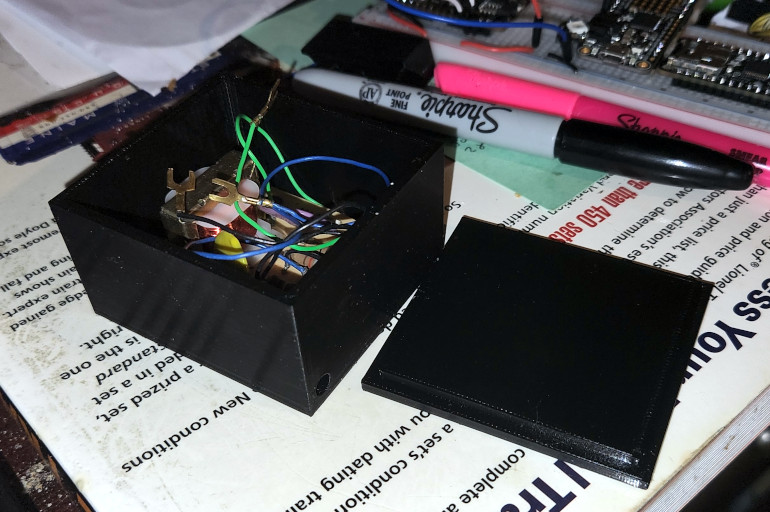
Another is for small project boxes with friction-fit lids.
The example below is PETg, and the difference between the internal dimensions of the box itself and the protrusion on the lid is, IIRC for this one, .2mm.
This will give a friction fit that will remain closed under normal circumstances, but is easily opened with a fingernail or knife blade.
For a more secure closure, I'll use a few dabs of Aileen's The Ultimate adhesive, which will hold securely but release with no damage when separated with a box knife.
RE: Designing and Printing Interlocking Parts - First time - advice, please?
Then I use a boolean subtract with a 0.2mm offset all round.
That's usually where I start. Then it depends on how tight you want the joint to be. For stuff I intend to publish to others, I usually err on the side of a larger tolerance unless that affects functionality. I usually also add a note to try scaling the model by 1 or 2 % up or down if they run into issues.
Formerly known on this forum as @fuchsr -- https://foxrun3d.com/
RE: Designing and Printing Interlocking Parts - First time - advice, please?
Just another thought: If you're new to designs, it may well be worth checking out the Design Principles for 3D Printed Parts course in the Prusa Academy. It's arguably a bit pricey at $10.00 and certainly not worth it if you have an industrial design background or a lot of experience but it is actually a lot better done than I expected and a good starting point for anyone who wants to learn more about designing parts. (No, I'm not getting paid by Prusa 🙂).
Indeed! I actually think it's great value at that price.
Another resource which is Teaching Tech's series on YouTube "3D Design for 3D Printing"- it moves a bit quickly but you can always stop and rewind, and I've found it a great reinforcement of stuff I thought I knew!
RE: Designing and Printing Interlocking Parts - First time - advice, please?
Another related thing you might do is check to see if you have a local 'makerspace' in your area.
These places usually offer free introductory courses in such things as 3d print drafting. That's how I got into this some time ago.
Some community colleges also offer free or low-cost noncredit similar courses as well.
RE: Designing and Printing Interlocking Parts - First time - advice, please?
My rule of thumb for assembly clearances is equal to the print layer height, as long as the machine and particular filament being used is well calibrated. So 0.1mm clearance with a an 0.1mm layer height etc.
Generally with clearance issues, it is actually mainly caused by sharp corners in the XY build plane, internal and external. External corners become oversized due to slight material oozing as the machine slows down at the corner, while internal corners become undersized also due to oozing and shrinkage. This can be compensated mostly if the printer has linear advance or pressure advance, but not all machines have this (the Prusa Mini does not for example). The main way to compensate for this is to put a small fillet or chamfer of the external corner. Ideally something like 1mm is a safe value but I use even smaller fillets or chamfers like 0.3mm if for whatever reason the CAD program doesn't like the large chamfers, or it severely affects the part functionality. I also have sometimes used an undercut on a mating internal corner, if for example it has to mate with a piece of lumber with a sharp edge.
I recently spent a considerable amount of time fully calibrating my machine. I had to design my own calibration files since others I was using were suceptible to localised shrinkage where small holes are undersized compared to larger ones, even when the machine is very accurately tuned.
This basically means it's impossible to get something without geometric devations in some areas, so some testing is generally inevitable, but clearance equal to the layer height is a good starting point. I generally stick to this pattern, and if necessary apply a little "XY size compensation" which is an expert Prusa Slicer setting, under the advanced section in print settings. An 0.1mm setting for example will offset all contours outwards by this amount, so -0.1mm will give 0.1mm extra clearance in that particular print. This allows people to compensate for clearance issues when printing other peoples models, although it requires the knowledge to use it.
I used the Ideamaker slicer previously and that has separate contour adjustment for holes and external perimeters, which is super handy for getting small holes the right size. The single XY compensation in Prusa slicer affects all contours, so while it could solve some clearance issues, it could create others on the same part e.g. I had a part with dovetails and screw holes, adjusting external perimeters affected the dovetail fit, while internal perimeters affected the hole size. It's a pretty rare issue to stumble into though.
RE: Designing and Printing Interlocking Parts - First time - advice, please?
I appreciate all the good advice on this topic - I'm sure there'll be more posts to go with this. While I have some thoughts and comments, there's one question I want to add now, since it might indicate something I don't know.
take a look at this modular screwdriver hex bits holder there is also the link to the tinkercad model.
I've looked at that and examined the parts in the 3D viewer Printables has. One question about it: I see the connector is a wedge shape, which makes sense. But I also notice the female part of the connector has a bottom, so the male can't just be slid in from the bottom of the part. However, there's no way to push the male in from the side. Am I missing something about how that one would work?
RE:
Of course, there can't be a bottom, or you wouldn't be able to slide the male part in. In fact, if you look at the second photo, you clearly see there's no bottom. Maybe I have too much time on my hands but I did look at the Tinkercad source, and indeed, no bottom. So somewhere between exporting from Tinkercad and uploading to Printables, a bottom materialized, and apparently the designer didn't notice.
While we're critiquing designs: For something like this, I would also fillet the outside edges of the male part and the inside edges of the female part, or after a few ins and outs the sharp edges in this design will break off. Alas, Tinkercad has no fillet function, and while I think Tinkercad has its place it's perhaps not the best design tool for functional models.
Formerly known on this forum as @fuchsr -- https://foxrun3d.com/
RE: Designing and Printing Interlocking Parts - First time - advice, please?
If you want to ensure that your users get the exact same outcome that you do, you could follow a procedure like this and then recommend that they follow the same calibration procedure and print settings. It's a bit of a pain but in theory they should get parts that are exactly the same as yours.
https://guides.bear-lab.com/Guide/Extrusion+multiplier+and+filament+diameter/8
RE: Designing and Printing Interlocking Parts - First time - advice, please?
I'm just going to put all my comments and thoughts in one post rather than making a number of different posts, replying to each person. I really appreciate this forum because people are so good at answering questions here!
I did like this interlocking. Cca 0,1mm from each part that should interlock (for ESP32cam).
I see how you use the rounded edges. Are there reasons you prefer that over square edges or sharper corners? Do they tend to keep their shape because it distributes the stress more evenly or anything like that?
I found the same kind of connector you have in your first photo - looks like it's kind of a universal thing. I'm going to be using several of them so I can adjust my cameras. I do most computer work in my study, which is in the house. The printers are about 400' away (well, about a 500' walk through the woods) in my workshop in the barn. Often I finish up designs in the evening and send them to the printers. I have had a few times the cameras saved me a lot of time and filament because I saw a print go wrong and could stop it. (And if it's not too late, I can walk down, clean the print bed, check the bad parts, and fix the issue before I leave the barn and restart the print and have it ready when I wake up.)
One is using 4mm or so (diameter) registration pegs, as in pegs on one piece, holes on the mating piece, for such things as model railroad buildings. I've found with PS, the Prusa I3, and common PLA filament, a tolerance of about .1 to .2mm between the radius of the hole and the radius of the peg will give a holding but forgiving fit. PETg seems to need a slightly higher tolerance, as in about .3mm.
I recently printed out a case for a Pi cam. It had 4 pegs and holes, but more for a snap-fit than just registration pegs, but that's something I figure I'll probably be doing soon. What I can't believe is that I haven't thought of printing buildings for a model railroad until now. I used to have one I was working on and my wife used to build doll houses. I've taken her to a few train shows and we both want to make a train layout down in the rec room in the barn so we can both work on it. I've noticed that many print items are like models - print all the pieces and put them together. When we can finally make a new layout, I'll be looking at parts, buildings, and other things I can print.
Another is for small project boxes with friction-fit lids.
For your friction fit lids, do you taper them at all have you just found settings for them to fit so there's enough friction to hold them in place?
Just another thought: If you're new to designs, it may well be worth checking out the Design Principles for 3D Printed Parts course in the Prusa Academy. It's arguably a bit pricey at $10.00 and certainly not worth it if you have an industrial design background or a lot of experience but it is actually a lot better done than I expected and a good starting point for anyone who wants to learn more about designing parts.
How long a course is it? Sounds well worth it if it's not just a short 30 minute video that glosses over the highlights.
Another related thing you might do is check to see if you have a local 'makerspace' in your area.
Good idea - one I would have overlooked. I live out on a large wooded lot we moved to about 2 years before the pandemic started. Moving away from the city, and with the pandemic, I got used to staying out here unless I had a really good reason to go into town. (Plus, I just like having so many trees and so few cars and stoplights around!) Believe it or not, I would not have thought of this because I've just gotten out of the habit of going to places or dealing with people in person. (I think I'm becoming a serious hermit out here!)
Generally with clearance issues, it is actually mainly caused by sharp corners in the XY build plane, internal and external. External corners become oversized due to slight material oozing as the machine slows down at the corner, while internal corners become undersized also due to oozing and shrinkage. This can be compensated mostly if the printer has linear advance or pressure advance, but not all machines have this (the Prusa Mini does not for example). The main way to compensate for this is to put a small fillet or chamfer of the external corner. Ideally something like 1mm is a safe value but I use even smaller fillets or chamfers like 0.3mm if for whatever reason the CAD program doesn't like the large chamfers, or it severely affects the part functionality. I also have sometimes used an undercut on a mating internal corner, if for example it has to mate with a piece of lumber with a sharp edge.
Thank you for all the detail and background!
Do you think the beveled connector, with sharper corners, would have more problems than if I stuck with 90° corners? Or if I used rounded connectors like @John Doe does?
This basically means it's impossible to get something without geometric devations in some areas, so some testing is generally inevitable, but clearance equal to the layer height is a good starting point.
Using layer height for a general measure - will that work as well for something in the XY plane where the clearance would not be determined by layers?
Of course, there can't be a bottom, or you wouldn't be able to slide the male part in.
Exactly what I was thinking!
So somewhere between exporting from Tinkercad and uploading to Printables, a bottom materialized, and apparently the designer didn't notice.
Okay, that makes sense. Having a bottom in there did not.
While we're critiquing designs: For something like this, I would also fillet the outside edges of the male part and the inside edges of the female part, or after a few ins and outs the sharp edges in this design will break off. Alas, Tinkercad has no fillet function, and while I think Tinkercad has its place it's perhaps not the best design tool for functional models.
This leads to the same question I asked above. Any thoughts on using rounded edges like @John Doe doe in the pictures he posted?
I'm also wondering if using the acute angles may make it easier for there to be fit issue and that maybe I should use right angles instead. (And then the idea of using rounded ends keeps coming up in my head, since I would think that the curves would distribute stress equally over that surface so it's less likely to have a few of the issues being brought up.
If you want to ensure that your users get the exact same outcome that you do, you could follow a procedure like this and then recommend that they follow the same calibration procedure and print settings. It's a bit of a pain but in theory they should get parts that are exactly the same as yours.
If I'm sharing someplace like on Printables, does uploading files for something like PrusaSlicer help with that, since it would contain the settings and someone would have to consciously change them if they wanted something different or wanted to experiment?
RE: Designing and Printing Interlocking Parts - First time - advice, please?
If you want to ensure that your users get the exact same outcome that you do, you could follow a procedure like this and then recommend that they follow the same calibration procedure and print settings. It's a bit of a pain but in theory they should get parts that are exactly the same as yours.
If I'm sharing someplace like on Printables, does uploading files for something like PrusaSlicer help with that, since it would contain the settings and someone would have to consciously change them if they wanted something different or wanted to experiment?
It would help as far as getting people to use the same basic print settings as you (perimeters, infill, scaling, etc.), but it wouldn't do anything for them squeezing the last bit of dimensional accuracy out of a print by calibrating the extrusion multiplier. That is something that is done to calibrate the machine for the individual spool of filament being used. In theory if the designer does it, and then develops the model using the data so obtained, and the end user does the same process to calibrate their machine to their filament, the parts produced should have exactly the same dimensions.
But as I said, it's a bit of a pain. Worth it if you are going to run off a bunch of parts with critical tolerances (such as for a printer) using most or all of the same spool of filament. For onesy-twosies, probably not so much.