The Ferris Wheel


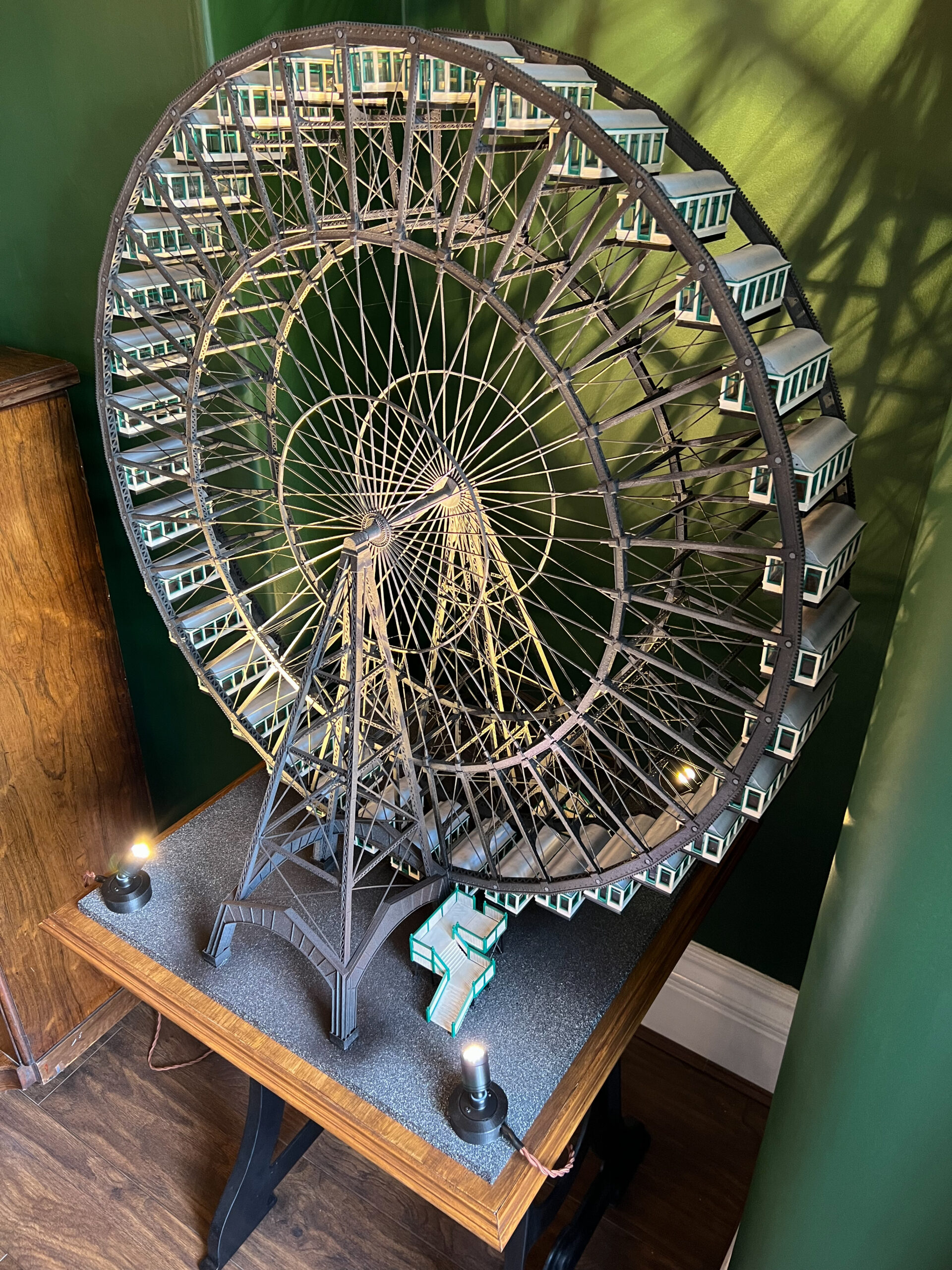

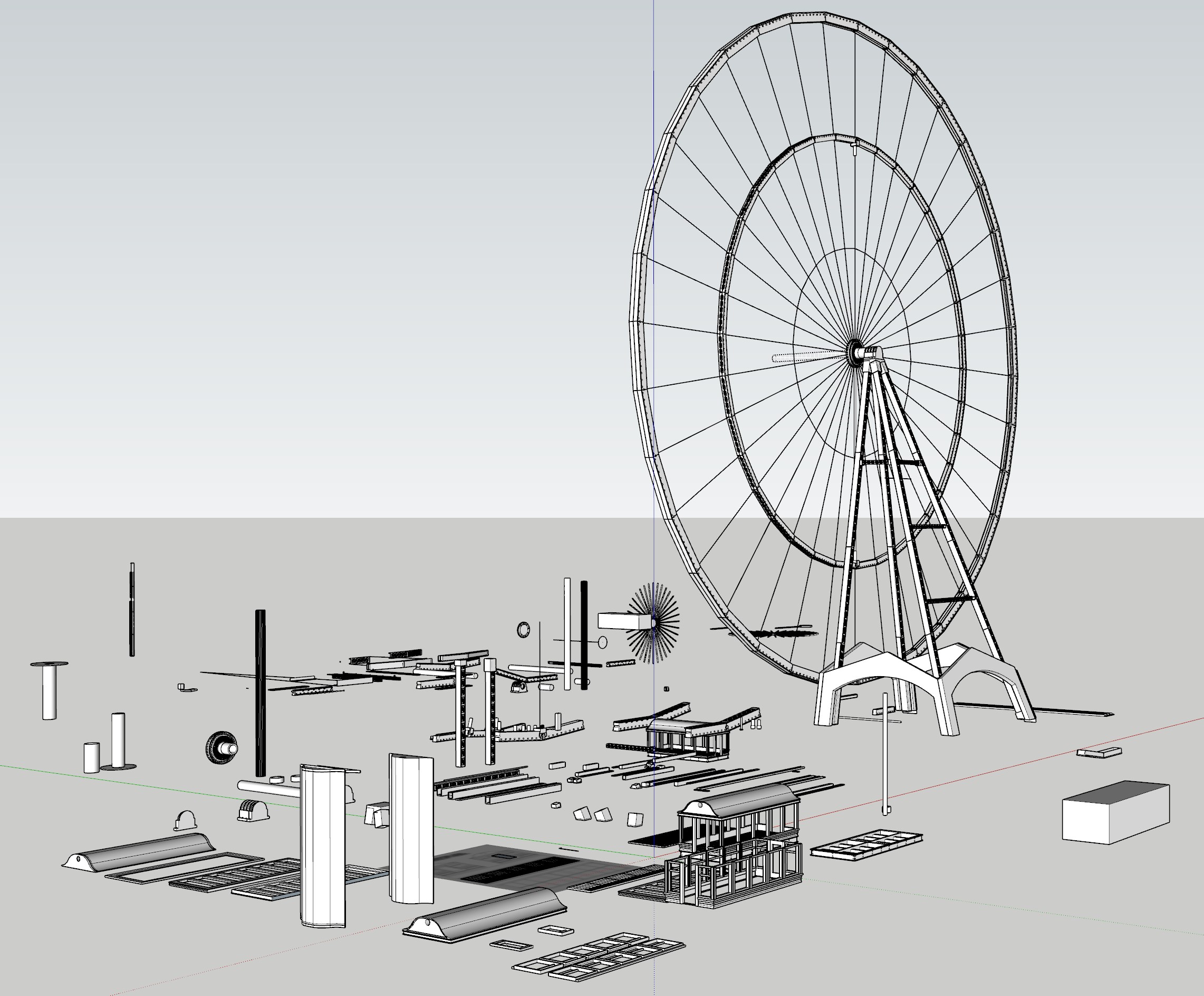
After over a years worth of work (on and off) I have just completed a scale model of George Ferris Ferris Wheel.Reverse engineered from photographs and books describing how the Wheel was built, it was designed completley in SketchUp and printed on a Prusa i3 MK3S+.It stands 90cm high by 87cm wide and consists of over a 1000 3D printed parts. I had intended for it to move using a motor and you can see the teath on the outer rim of the wheel just like the real one; it rotates freely and the cars all self level but it was just two difficult to motorize it.
RE: The Ferris Wheel
Great work! This reminds me a little of our "Riesenrad" in Vienna (Austria).
wbr,
Karl
Statt zu klagen, dass wir nicht alles haben, was wir wollen, sollten wir lieber dankbar sein, dass wir nicht alles bekommen, was wir verdienen.
RE: The Ferris Wheel
Very nice!
RE: The Ferris Wheel
Impressive.
What is the issue with motorisation? Perhaps we can help...
Cheerio,
RE:
@Karl-Herbert
That's because the Viennese Ferris Wheel is, to my knowlede, the 19th century Ferris Wheel which is still around.
Mk3s MMU2s, Voron 0.1, Voron 2.4
RE: The Ferris Wheel
Hi, so the issue with turning the wheel was not so much the motor itself... I made a gearbox and motor assembly that turned the wheel but as the two outer rims are slightley out of alignment (not visable to the eye) it wouldnt turn the whole 360 degrees so I had to make a decision to make the wheel again or stick to a static wheel... I stuck to the later decision.
First thought:
You might try a sprung follower on the opposite side to oppose the pressure and keep the drive train in contact. If just the follower isn't enough to maintain the contact, mount the drive train on a pivot and use another spring to push it in place.
Cheerio,
RE: The Ferris Wheel
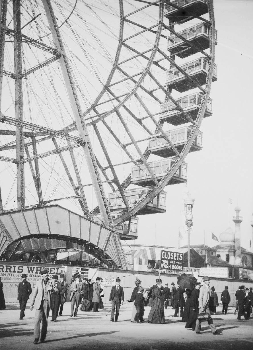
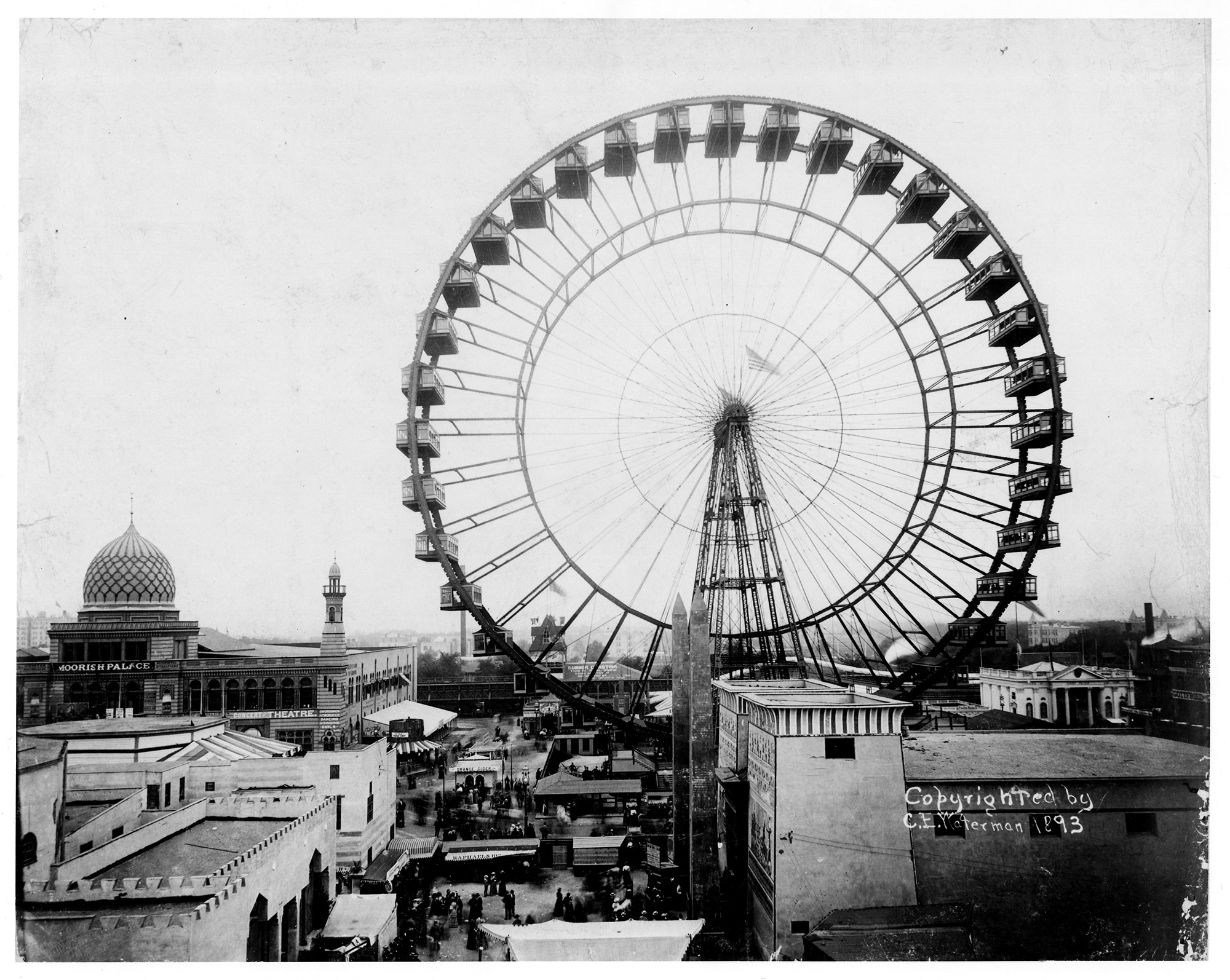
Wow, that is seriously impressive! Amazing attention to detail and faithful to the original ‘Ferris Wheel’ from the 1897 World’s Columbian Exposition (World’s Fair) in Chicago.
Well done!
RE: The Ferris Wheel
This is amazing! Great job! Is this available to download and/or purchase?
RE: The Ferris Wheel
Wauw!
Loving the learning curve!
RE: The Ferris Wheel
Amazing.
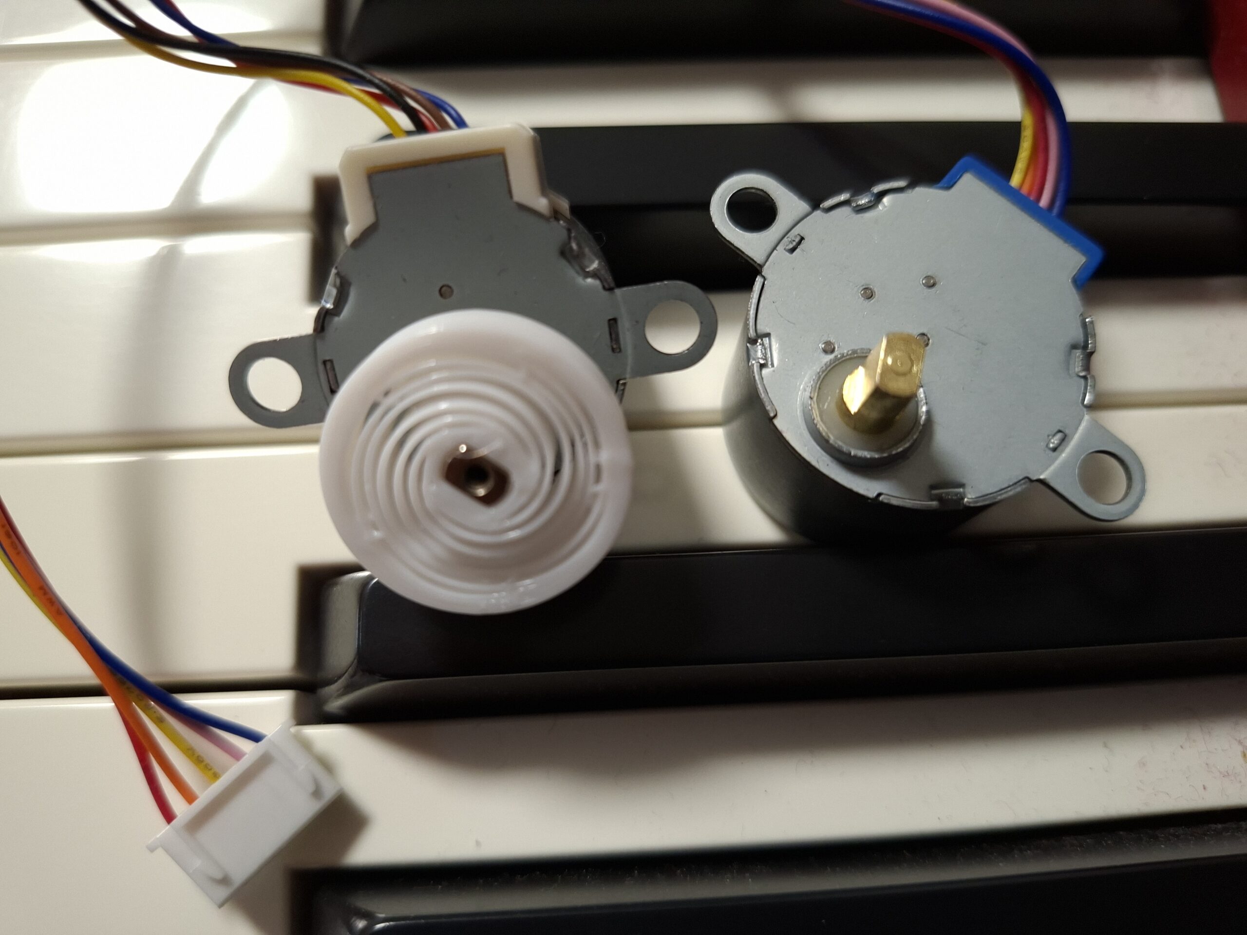
For a motor, you could have a look whether a 24BYJ-48 stepper motor fits mechanically. It's kind of a standard component (there is also 28BYJ-48, even more popular but slightly larger). A 5 V version would make most sense to me.
Those are used to drive clock hands, slow but controlled rotation is not a problem (it has ~1/64 internal gear after the stepper). To keep the software simple, it could be coupled by friction e.g. just stick a suitable piece of silicon tube over the drive shaft as a coupler. It doesn't have too much torque, so the coupling should be weak enough to slip before the stepper skips steps.
RE: The Ferris Wheel
Additional thought (sorry for the spam, can't edit): An elastic wheel might work with said steppers, to drive somewhere against the rim where it can be hidden most conveniently.
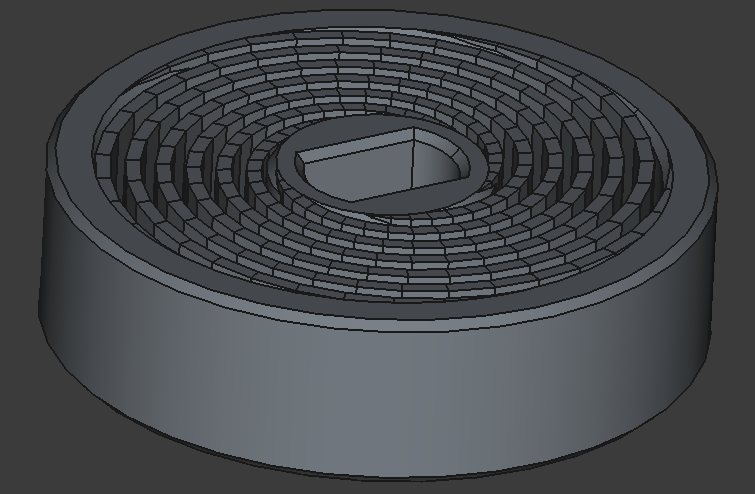
Attached a parametric design for adjustments, just put in the numbers you need (FreeCAD 1.0.2, run via "Macro menu", select the resulting object and export as .step). I test-printed it in TPU95 (picture: placed on the 24BYJ-stepper motor in question with its larger 28BYJ- sibling in the background). Printed on Core one default 0.4 mm nozzle.
The wheel is extremely soft as a starting point, but stiffening is straightforward in the script. It could also be extended into a cylinder beyond the motor shaft, at least for a few cm.
I hope this is maybe of some use...
Putting it also on Printables.