Prusa Mini : difference between CAD sizes and Printed sizes (both X, Y and Z) : any correction through M92 command on Prusa Slicer?
Hello Guys
Just starting with my new Prusa Mini…but some knowledge grabbed since Nov. 2017 and few 3D Printers bought and tuned at home …
So after Z calibration (found - 0.83 mm OK) I printed a beautiful Benchy with Prusament PLA (galaxy Black) 😍
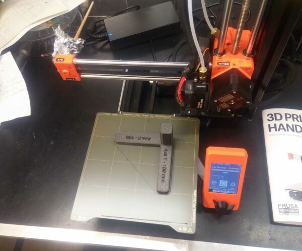
OK, but then I printed 2 basic calibration parts to assess dimensions accuracy.
One part is the one defined by Danish 3D Printing on Thingiverse
(link: www.thingiverse.com/thing:2474201 )
Youtube: https://www.youtube.com/watch?time_continue=3&v=sGroxKI_-O4&feature=emb_logo
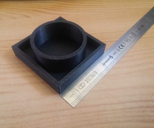
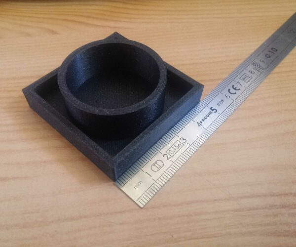
The second one is home made to assess square sides dimensions (50mm) and 40mm cylinder external Ø to assess circular interpolation (3D printers cinematic performance) through roundness .
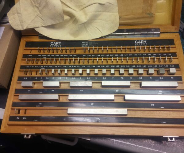
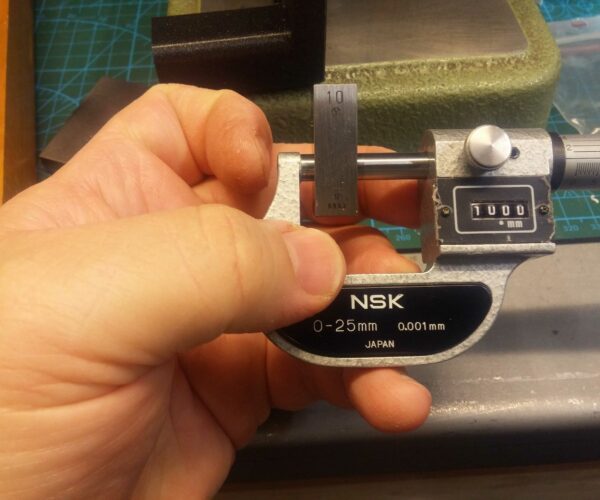
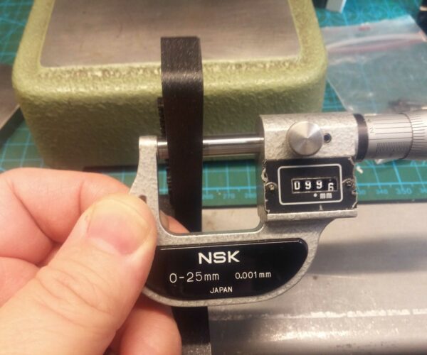
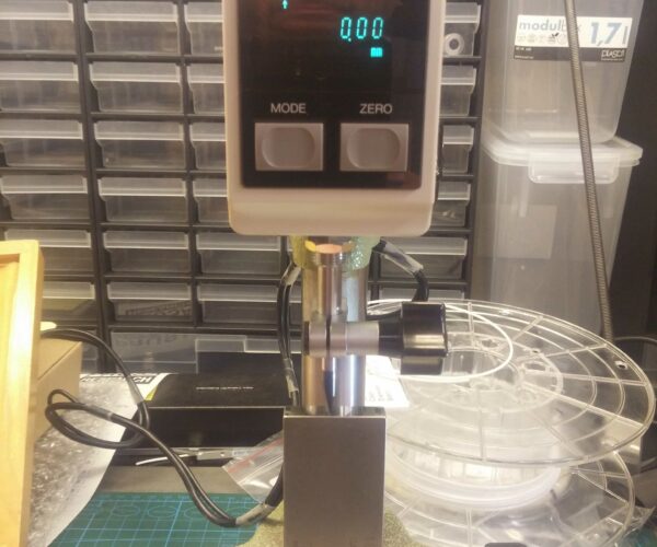
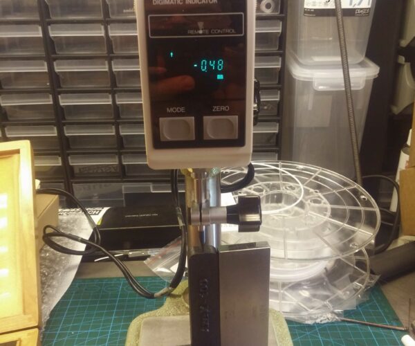
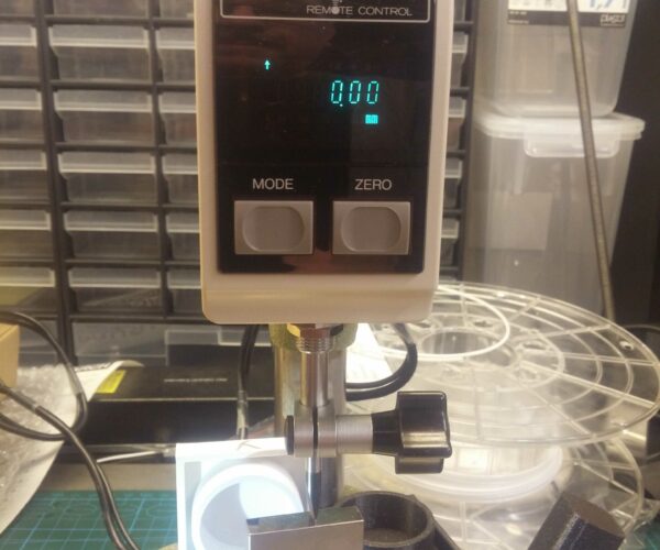
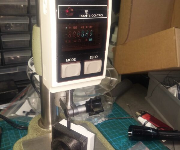
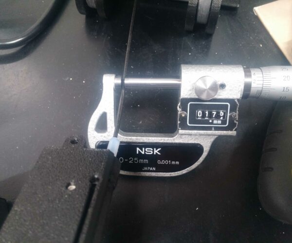
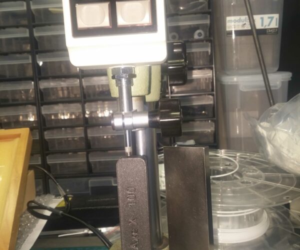
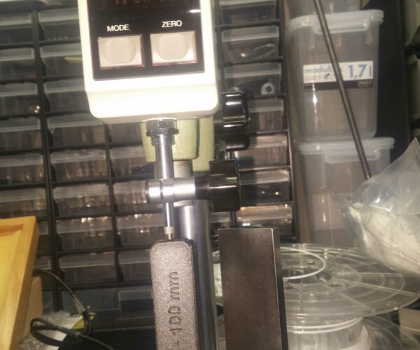
Some photos below (lot more in stock!) and here are my findings: 🤔
Part type CAD dimension Axis measured diff. vs. CAD
Calibrator 10mm Z -0.04 mm (9.96 mm)
Calibrator 50 mm Z -0.23 mm (49.77 mm)
Home made 50 mm X -0.23 mm (49.77 mm)
Calibrator 100 mm X -0.48 mm (99.52 mm)
Home made 50 mm Y -0.18 mm (49.82 mm)
Calibrator 100 mm Y -0.53 mm (99.47 mm)
From both testing parts, we can observe that measurement differences are pretty much proportional to dimensions: e.g. Z axis : 10mm gave -0.04mm and 50 mm gave -0.23 mm . So same ration (5) between dimensions and measurements.
This is the same for X axis. But not for Y: I should be around -0.36mm on 100 mm dimension instead of -0.53 mm …
Anyway, this is not pretty nice, and on all my previous printer, I can correct/adjust this through Simplify3D by adding 1 line into starting script such as: M92 X80.11 Y79.96 Z398.72 E120 🙄
And then I can tell you that prints are 0~0.03mm accuracy from CAD dimensions. 😎
But…to do so usual firmware values need to be known, and are usually like this: M92 X80 Y80 Z400… (extruder E… value depend of its design, gear ratio, etc). So is that “80” value set into Mini Firmware? Allo Prusa team: someone could help me here? 🧐
I am absolute beginner into Prusa Slicer, so I don’t know yet if such “starting script” can be added, such as in S3D.
Otherwise, I will move to S3D to drive/slice for the Mini as well…
I will try to move further into this, but should anyone have some nice advices to implement such M92 correction then please let me know.
Best regards from FRANCE!
Sylvain
J'essaye de faire, mesurer et partager...plus pratique que théorique, peu de blabla, des résultats… La preuve incombe à celui qui affirme….en faisant et mesurant
I just found scripts page! New trials to come...
Hello Guys,
Just after my above post I found script pages into Prusa Slicer.
I will try some axis correction values through M 92.
Then I will let you know
Best regards from FRANCE!
Sylvain
J'essaye de faire, mesurer et partager...plus pratique que théorique, peu de blabla, des résultats… La preuve incombe à celui qui affirme….en faisant et mesurant
Prusa Mini : (solved) difference between CAD sizes and Printed sizes (both X, Y and Z) : Starting script M92 command works great!
Hello,
So I printed, measured, computed and …reached my target, means to print very accurate dimensions parts on both X and Y axis.
I made hypothesis that firmware defined M92 values were something like this: X80 Y80 Z400… so I used XYZ calibrator approach (Danish 3D Printing design) and launched a print…ouups : I observed that first layer was drastically smaller than expected…and the second layer was not adequate (extruder rubs on first layer, no extrusion)because of inadequate Z elevation.
I measured this 1 layer part dimensions on X and Y with a ruler: around 80 mm both directions.
So I assumed firmware value should be… 100 (and not 80 as guessed). But what could be Z (because this is not stepper/belt configuration but stepper/leadscrew… Well, I tried to correct X and Y only, through the M92 command.
After 2 trials, my calibration part went just perfect. When I wrote perfect, it means that dimensions in X and Y are perfectly at 100,00 mm …which I did not expect!
Usually on my previous 3D printers I reach target value ± 0,03 or so, and I’m already pretty happy with…
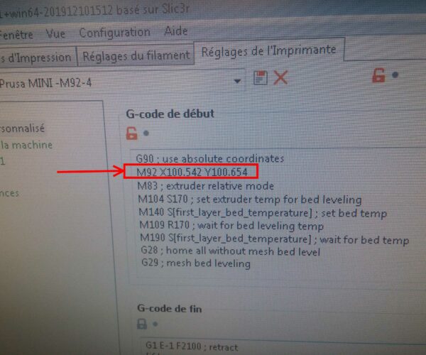
So inserted second line into Prusa Slicer , starting script section: M92 X100.542 Y100.654
Anyway, some photos here below…
Now I have to investigate how it works on Z direction… and I will post any progress here later.
By the way, anyone having made such investigation and trials, please let me know the M92 values you found...
Best regards!
Sylvain
The PLA Ø is not any issue: Prusament PLA is at 1,75mm diameter...assessed many times during my trials...
Click on photos below ,to observe under full size
J'essaye de faire, mesurer et partager...plus pratique que théorique, peu de blabla, des résultats… La preuve incombe à celui qui affirme….en faisant et mesurant
RE: Prusa Mini : difference between CAD sizes and Printed sizes (both X, Y and Z) : any correction through M92 command on Prusa Slicer?
Hi Sylvain,
I'm in a similar boat, also noticed that my prints are off in terms of dimensions (and I mostly plan to use the Mini to print mechanical functional parts). Compared to a Zortrax M200 which I borrowed for a few months, the Mini isn't looking too good (didn't have to do any calibration on the M200, everything was coming out pretty much bang on), two examples:
- simple shaft collar, 30mm diameter, 10mm thick, 6.35mm bore through the middle. Part came out as 29.70mm diameter, 9.90mm thick and 6.30mm bore
- 20mm x 20mm x 20mm XYZ calibration cube. Part came out as 19.90mm x 19.90mm x 19.95mm
I've not yet tried printing long pieces, so I have no idea whether the error grows and is proportional to the length (so cumulative). I have emailed Prusa support to see what they suggest.
What print settings / layer settings are you printing with when doing calibration?
Regards,
Tom
RE: Prusa Mini : difference between CAD sizes and Printed sizes (both X, Y and Z) : any correction through M92 command on Prusa Slicer?
For the first layer, there is a setting called Elefants Foot compensation, i think it's under advanced in print-tab.
It makes the first layer a tiny bit smaller to compensate for the first layer squish down to the buildplate.
Prusa Mini+ kit. BondTech extruder. FW 5.1.2
Prusa MK3S+ kit. Stock. FW 3.11.0
Prusa MK3S+, used. Stock. FW 3.13.3
RE: Prusa Mini : difference between CAD sizes and Printed sizes (both X, Y and Z) : any correction through M92 command on Prusa Slicer?
@tompjagiello
Hello Tom, and sorry to be late: I did not read your post until today!...
Attached you will find a kind of test report I emailed to Prusa few weeks ago. no response since, but I guess they have many other tasks to manage..
Please have a look into attached file, and try the calibrator XYZ online calculator to find/set adequate value for M92 command. Focus on first 5 pages...because next ones remain remain in French.
My Mini is just printing perfectly since correction Values are inserted into the starting script G-Code.
Hope this will help.
Best regards
J'essaye de faire, mesurer et partager...plus pratique que théorique, peu de blabla, des résultats… La preuve incombe à celui qui affirme….en faisant et mesurant
RE: Prusa Mini : difference between CAD sizes and Printed sizes (both X, Y and Z) : any correction through M92 command on Prusa Slicer?
Just stumbled upon this thread and I just had to comment on your work, very well done, pdf and everything!
I will definitely try this on my Prusa mini.
RE: Prusa Mini : difference between CAD sizes and Printed sizes (both X, Y and Z) : any correction through M92 command on Prusa Slicer?
Great post, tried it and it works great. Got the dimensions a lot more accurate in XYZ direction. But still I'm having problem with holes: I know that holes shrink and that you have to design them bigger. But I'm getting a shrinkage up to 0.3mm on a 4mm hole. That is especially annoying, when you try to print some PTFE tools, because the tube never fits into the holes. Is that normal?
RE: Prusa Mini : difference between CAD sizes and Printed sizes (both X, Y and Z) : any correction through M92 command on Prusa Slicer?
@oliver
Hello Oliver,
I'm happy if you improved your prints accuracy.
Regarding any circular shape, you need to investigate into their geometry upfront: is that a "real" circle or an ellipse like indeed….pretty often it is the second hypothesis...
From printer cinematics point of view, if X and Y dimensions are accurate... then any circle shape should be OK...and it is not that easy because it depends a lot about how printer is built and how axis are designed: cartesian, core XY, H bot...
To check this, a 3 or 4 mm Ø is not easy to do...this is why I designed this simple test part:
The external square shape is defined at 50 mm (external sides) the cylinder is defined at Ø 40mm (external side). The STL is here enclosed if you whish to use it.
May I suggest you to print it, making careful axis X and Y identification. Then you perform measurement of the square shape (which should be OK if you corrected dimensions with M92 command) and you check the cylinder ext Ø all around it.
Then it is important to check if you got square angles 90° at each square shape angle.
Indeed, if X and Y are not perfectly perpendicular, then combined shapes of both axis won't be marvellous I guess…
Most of 3 D Printers owner don't check their machine geometry, because it request know how, suitable gages, and reference block gages to make it correct.
And this is where axis X and Y is important because you could find the circle shape deformed along 1 axis (best case) or, in combination off both (not easy to fix..) . Check belts tension, mobile parts guidance (clearance). Another tip is to print a second time this test part, by rotating it 45°: then each shape , square and cylinder , are now combination of X and Y...and if cylinder is not accurate, then square should not be either...
All above mentioned are from my own experiences and findings. I can't guarantee This will lead you to problem solving … but I'm sure It gives you some checklist you will have some benefit from.
Hope it will be
Best regards
Sylvain
J'essaye de faire, mesurer et partager...plus pratique que théorique, peu de blabla, des résultats… La preuve incombe à celui qui affirme….en faisant et mesurant
RE: Prusa Mini : difference between CAD sizes and Printed sizes (both X, Y and Z) : any correction through M92 command on Prusa Slicer?
@sylvain-t2
Hi Sylvian,
thanks again. Will look into that.
Regards, Oliver
RE: Prusa Mini : difference between CAD sizes and Printed sizes (both X, Y and Z) : any correction through M92 command on Prusa Slicer?
So I've been doing loads of tests recently, printing loads of first layer samples to get the first layer calibrated properly and printing various dimension checking models to see how accurate the prints are and unfortunately they are not that great.
I've contacted Prusa about this and they suggested doing overextrusion checks as per their article:
https://help.prusa3d.com/en/article/extrusion-multiplier-calibration_2257
Which I did and after measuring the cube walls with a digital Mitutoyo 0-25mm mic, I got an average of 0.45mm so bang on what it should be. Afterwards I printed a few parts and didn't really like the top layers on them, so I dropped the extrusion multiplier to 0.95 and it funnily made the first layer better :O surprise as I assumed it would make it worse, but anyways, overall it was an improvement so I'm sticking to it.
After the above I did more dimension checks and on a 20mm x 20mm x 5mm block and got 19.84mm x 19.82mm x 5.00mm measured wall centre-to- wall centre on each wall. Corner measurements however are 20.03mm x 19.98mm x 5.04mm, so almost spot on, but as it turns out all the corners are bulging, so are basically overshot and across those the parts are accurate :/ I've read that this is caused by overextrusion in the corners and that slower printing in corners works for this, but small perimeters are already done at 25mm/s which seems slow anyway.
So until I resolve the above issue I don't really want to touch the M92 commands as it will just make those bulges bigger and oversize parts.
@Sylvain have you got any bulging on corners on your parts? I'm talking about something like this:
https://community.ultimaker.com/topic/21306-how-to-prevent-overshoot-corners-or-round-edges/
Regards,
Tom
RE: Prusa Mini : difference between CAD sizes and Printed sizes (both X, Y and Z) : any correction through M92 command on Prusa Slicer?
Thanks for this excellent, thorough thread about this problem. I just ran into it with my MINI.
Question: if I use the correction you posted (M92 X100.542 Y100.654) will this work, or is the correction for every MINI unique?
Thanks
RE: Prusa Mini : difference between CAD sizes and Printed sizes (both X, Y and Z) : any correction through M92 command on Prusa Slicer?
Question: if I use the correction you posted (M92 X100.542 Y100.654) will this work, or is the correction for every MINI unique?
I just answered my own question (partially). I put this M92 command in my startup in prusaslicer and printed a 20mm cubed calibration cube. With my analog calipers it looks spot on. I'll leave the M92 in place and continue to test it for a while.
RE: Prusa Mini : difference between CAD sizes and Printed sizes (both X, Y and Z) : any correction through M92 command on Prusa Slicer?
@bf
Hello,
May I suggest you to go deeply into, first, reading "calibrator XYZ" written/published by Danish 3D Printing (you will find this on thingiverse as well as on youtube. Have also a look into varous PDF I published here...
You need to make prints and measurements to determine which correction value to enter into M92 command line.
My values could be not adequate to your measured differences on parts. So each printer, each case needs its own investigation and measurements...
Hope this could help
Best regards
S.T.
J'essaye de faire, mesurer et partager...plus pratique que théorique, peu de blabla, des résultats… La preuve incombe à celui qui affirme….en faisant et mesurant
RE: Prusa Mini : difference between CAD sizes and Printed sizes (both X, Y and Z) : any correction through M92 command on Prusa Slicer?
@tompjagiello
Hello,
I am not a great supporter of "more plastic into the parts" Again, I strictly follow the procedure described by Danish 3D Printing with his calibrator XYZ. Now, true I changed part I use for calibration, to be more accurate into measurements, so in correction as well.
Bulging on corners increase according to printing speed: Easy to understand that a moving head can't keep constant velocity to make a right angle, meanwhile extruder speed doesn't change.... try to reduce significantly the printing speed...then observe the visual effect on corners....
A technical approach to solve this is described as "Linear advance".
Please make some google research on this for more details.
Prusa published also some stuff: https://help.prusa3d.com/en/article/linear-advance_2252
May I suggest you to keep extrusion factor to 0,95 or 1 , then to read and follow stricly procedure "Calibrator XYZ" published by Danish 3D printing?... then dimensions difference should be drastically reduced...
Hope this will help
Best regards
S.T.
J'essaye de faire, mesurer et partager...plus pratique que théorique, peu de blabla, des résultats… La preuve incombe à celui qui affirme….en faisant et mesurant
RE: Prusa Mini : difference between CAD sizes and Printed sizes (both X, Y and Z) : any correction through M92 command on Prusa Slicer?
Thank you for your help. I will go through the procedure provided by the Danish 3D Printing youtube video. Thank you for taking the time to reply.
RE: Prusa Mini : difference between CAD sizes and Printed sizes (both X, Y and Z) : any correction through M92 command on Prusa Slicer?
I performed the Danish 3D calibration process using this tool https://weitling.info/d3p/index.php?sfm_sid=6272 and the results are almost perfect for X and Y--within the 0.05mm that can be attributed to first layer expansion. I'll continue to refine the settings.
Do you have any suggestions on how to calibrate the Z axis? The 50mm tall calibration print came out to 49.90mm in height. Putting a corrective Z height M92 value in the Gcode startup results in the first layer being printed about 1mm too high (off the bed surface) so I had to remove it. Is there another way to calibrate print height?
Thanks again for your help.
RE: Prusa Mini : difference between CAD sizes and Printed sizes (both X, Y and Z) : any correction through M92 command on Prusa Slicer?
@bf
Hello Bf
Reaching 0,05mm bandwidth is somehow "respectable", and you could classify it Perfect (not almost perfect). With such connstruction component, open loop motion system, extruded plastic parts.... it is even incredible from my point of view (even being into same tolerance bandwidth with my printers...) 😲
And I guess you should be pretty happy with (considering previous results you had, without M92...)
Regarding first layer expansion, it is known as "elephant foot effect" 😏
You can attenuate it using Prusaslicer: there is a parameter to adjust for this: 👍
https://help.prusa3d.com/en/article/elephant-foot-compensation_114487
Regarding de Z axis compensation, you have to pay attention where you insert the M92 line, because it may affect autolevelling if placed before, and then may explain the 1mm difference/error of first layer.
Also have in mind that steps/mm for Z and Y are usually same, but steps/mm for Z is pretty often different settings. If you send M501 command to the printer, it should display/send back all factory/Eprom settings, including original/preset of M92 all axis values...To be honnest I don't remember those right away: it is 100 for X and Y..but not so sure right now for Z... If I find back I will post it
Hope this will help a few...
Best regards
S.T.
J'essaye de faire, mesurer et partager...plus pratique que théorique, peu de blabla, des résultats… La preuve incombe à celui qui affirme….en faisant et mesurant
RE: Prusa Mini : difference between CAD sizes and Printed sizes (both X, Y and Z) : any correction through M92 command on Prusa Slicer?
Thanks again. I agree that 0.05mm is perfect. I'm very happy and can't thank you enough.
The factory firmware value for M92 Z is 400. I just realized that I had a major error in my Z value calculations. The corrected value for my printer should be Z400.80 based on the test print. I will put my M92 line after G29 (mesh bed levelling) as you have very helpfully suggested. Testing now...
RE: Prusa Mini : difference between CAD sizes and Printed sizes (both X, Y and Z) : any correction through M92 command on Prusa Slicer?
@bf
looks like you are on the right way!
When I make such approach I keep this in mind: considering factory value, if part dimension is a bit too small, this should induce a bit more steps/mm to bridge the gap on involved axis movement.
And on the other way: if dimension is a bit too large, then I should reduce a little bit the steps/mm value.
Both cases, we are talking about few numbers...after the coma...usually
Cross my fingers for your Z calibration test!
Keep us updated!
Best regards
S.T.
J'essaye de faire, mesurer et partager...plus pratique que théorique, peu de blabla, des résultats… La preuve incombe à celui qui affirme….en faisant et mesurant
