My Method For Setting First Layer Z Height..
Hi all,
My first post and it's a long one sorry! I have seen a lot of posts about setting the first layer Z and after wasting far too many hours trying to do it by using the built in calibration or printing 80x80 squares for hours on end, I figured out a reliable and more importantly quick, method. I have also seen posts about how using feeler gauges is not ideal but I think that is also because its "subjective" to a certain extent, you have to adjust it until it feels right.. well ,what's right? hopefully this makes sense and there is not too much "feel". I hope this helps someone and it can probably be adapted for other printers as well.
First layer Z adjust method.
Before doing all this ensure that the printer is square! If you have done the nylock mod for the mini ensure you have levelled as best you can before doing this! I set the printer to X90 Y90 so that the nozzle is directly over the fixed spacer of the bed, this should be the most consistent place to measure from. If you want to use the printed tool (not mine but a very good one to download here) to set the SPINDA Height print it first on a working printer, if you are setting up your printer for the first time or don't have access to another working one, find something that is exactly 1.5mm thick, a piece of card or 1.5mm drill bit for example, use callipers or a micrometre to confirm and run the built in Z calibration at least once to save a value in the firmware.
Set Up SPINDA
- Skip this section if you are confident that your SPINDA is 1.5mm off the heat bed. Using the printer menu move the extruder to X=90 Y=90 Z =90
- Allow printer to fully cool if it isn’t already, remove the steel sheet and then loosen, but not remove, the SPINDA screws. Turn off stepper motors and carefully by turning the Z screw lower the extruder until the nozzle is close to the heat bed.
- Using the printed tool or an object 1.5mm thick, align it with the SPINDA Probe and carefully lower the Z axis by hand until the nozzle just touches the bed. I find it helpful to move the bed back about 5mm at this stage so the nozzle touches down just in front of the torx screw head on the heat bed.


- With the nozzle touching the bed (tip: look for any movement at the end of the X axis if it moves even slightly you are too low. You can’t feel any resistance in the Z screw so be careful..!) adjust the SPINDA so it slightly resists the movement of the tool. You should be able to just slide the tool in and out without the X axis lifting and feel the probe dragging on the tool.
- When you are happy tighten the SPINDA screw back up and move the Z axis back up 50mm or so, enough to put the steel sheet back on.

Set Z Height
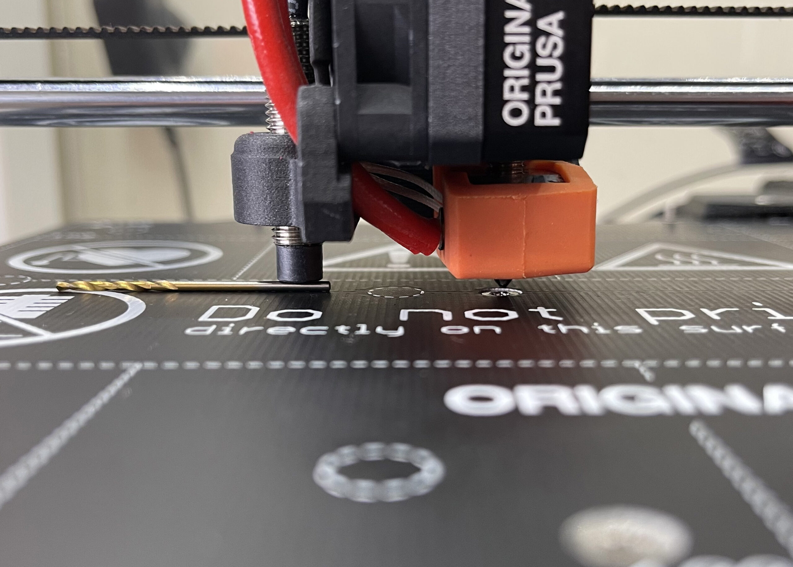
- Now connect to Octoprint (you need terminal access for this so Octoprint , Pronteface or similar) at the terminal type G28 to auto home the printer. Once that has completed type the following in sequence and wait for each move to complete before typing the next one: G1 Z20; G1 X90 Y90; G1 Z2 The first move is to lift the extruder so there is plenty of clearance for the next move, the next centres the nozzle over the print bed directly above the centre fixing. This is the most consistent place to measure from especially if you have done the nyloc mod. The last move is to lower the nozzle again to a safe starting point. At this point use the tune menu on the printer to live adjust the Z height, turn it all the way up to 0mm or 0.5 if you are feeling confident about your setting of the SPINDA probe….
- Now at the terminal type G1 Z0.2 the nozzle should move down and still be well clear of the print bed
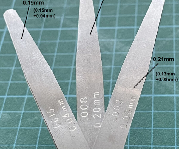
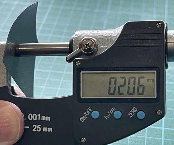
- Then using a clean feeler gauge (thoroughly wipe the oil off the blades!! Or it will contaminate your steel sheet!) you need a combination of 3 blades, I use 0.2mm as the main one, a 0.15+0.04mm to make a 0.19mm and a 0.13+0.08mm to make a 0.21mm. arrange the blades in a sort of spaced three finger setting in the order 0.19 – 0.2 – 0.21. At this stage nozzle size vs layer height doesn’t matter we are just calibrating the printer to a known value. Later on when printing a test square, nozzle size and first layer height become relevant.
Note: You can use values other than 0.2mm it doesn’t really matter at this point as long as you can get 3 blades one very slightly smaller and one very slightly bigger than nominal it will work, just remember to move the nozzle in step 7 to your chosen nominal value first…!
- Using the feeler gauge slide the 0.19 under the nozzle and then using the live adjust menu lower the nozzle until you feel a small amount of resistance on the blade. Now slide the 0.2 under the nozzle if it fits easily, slowly lower the nozzle until the 0.19 fits and the 0.2mm wont without a bit of force. Again keep an eye on the end of the X-Axis for any movement, there is enough flex in the arms to allow the 0.20mm in by forcing everything up giving you a false reading so don’t force it! Keep swapping between the 2 blades to get a good feel for it. This is your lowest value i.e. the nozzle is between 0.19 and 0.2mm from the surface.
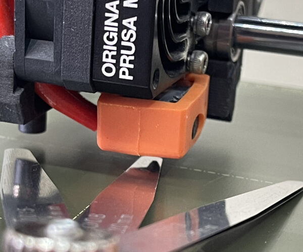
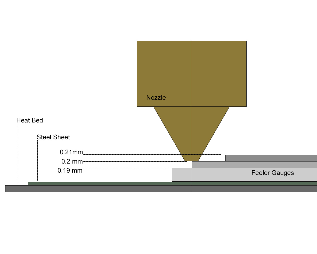
- When you are happy repeat for the 0.2mm vs 0.21mm blades, lift the nozzle a few clicks until the 0.2mm fits but the 0.21mm wont, remember don’t force it! This is your highest value i.e. the nozzle between 0.2 and 0.21mm from the surface. Now keep swapping between all three blades, you should end up at a value where the 0.19mm fits easily, the 0.2mm fits with a bit of resistance and the 0.21mm won’t fit, With a bit of practice you should be able to get the nozzle to be perfectly 0.2mm off the surface…. This Little diagram hopefully explains what you are trying to achieve!

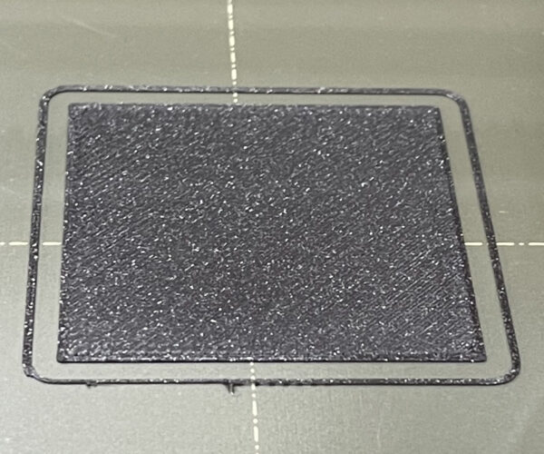
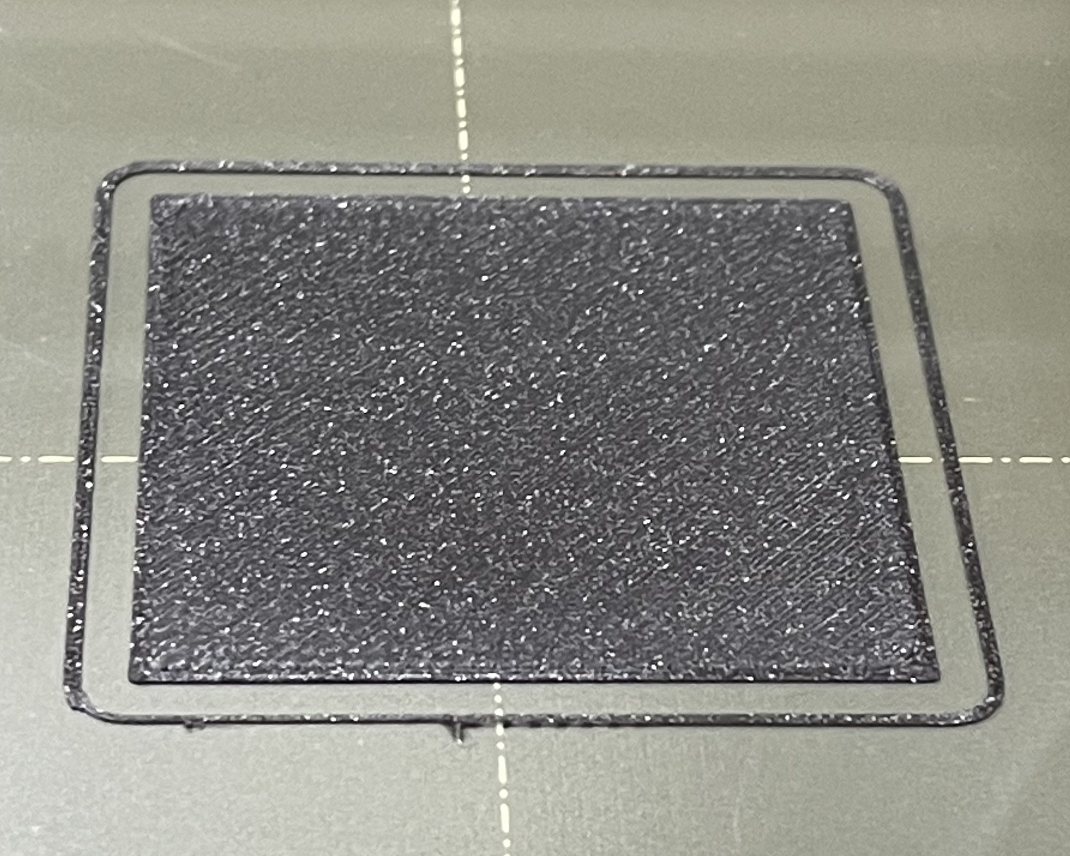
- When you are happy click done on the menu and at the terminal type G1 Z90 to move the nozzle up and out of the way, let the printer cool down again if it was at all hot, clean your print sheet VERY THROUGHLY!! When you are ready slice and print a 40x40mm 0.2mm thick square. Many people use an 80x80 square but I’m impatient and a 40x40 prints a lot quicker, I’ll print an 80x80 later to confirm and fine tune if need be. I tend to use the default Prusa settings e.g. default Prusament PLA for filament and 0.2mm quality for print settings if using Prusament PLA and a 0.4mm nozzle, for this rather than any I have saved, as it prevents any slicer settings I have made interfering with the print. Watch carefully as it prints it should be almost perfect!

- When it’s done carefully asses it and double check with a micrometre if need be, it should be very close to 0.2mm mine are normally 0.21-23mm on the satin sheet a little more for the textured a little less for the smooth PEI sheets for example. Don’t worry too much about the exact number, remember we are talking about 0.01-0.03 of mm of warm plastic! It’s more important that it sticks to the sheet well, it’s consistent all the way across and there are no gaps or excess material at the edges. The micrometre just confirms you getting what you expect and not 0.6mm or something crazy! In this test for example, I ended up with a Z value of -0.680 for the smooth PEI sheet
- Repeat steps 6 and 7adjusting the Z value up or down very small amounts if you are not happy with the results, if you are happy with it skip this step and give yourself a gold star, you got it right first time! This is where the 40x40 square comes in handy as it prints quickly. if you need to move it more than a couple of clicks each way (remember the highest and lowest values from steps 4 and 5? Those were your limits!), either you didn’t do steps 3-5 properly or there is something else wrong like over/under extrusion, poor filament or, most likely, the steel sheet is not clean enough.
- If I’m happy with the 40x40 square at this point I’ll print an 80x80 square and double check it, its nearly always good but occasionally I move the Z up or down a touch depending on the edge quality.


That’s it done, now repeat the Set Z Height for any other sheets you have and don’t forget to save the settings on the printer for each sheet! Oh and be careful, it's not my fault if you screw your printer up!
RE:
test because this forum software ate my homework! GRRRR
OK re-typing ALL the stuff I typed earlier 🙁
First, thanks for posting this procedure. I am a grease monkey, so I totally understand how to use feeler gauges. However I am trying to understand exactly what is it you are trying to do.
Questions:
1. Are you trying to set the gap between the nozzle and the print surface to 0.2 mm?
2. Why exactly 0.2 mm? Half of nozzle?
3. Are you using a 0.4 mm nozzle, the default one?
Asking because I have a 0.8 nozzle mounted now, and was wondering what should I set that gap to.
Thanks again for your input 🙂
RE: My Method For Setting First Layer Z Height..
Ok I will try to answer as best i can....!
- technically yes, it's more like telling the printer that "this position is 0.2mm" the SPINDA can only get it fairly close so setting the Z value is just a more accurate calibration.
- No particular reason other than that's the most common layer height! you could in theory use any dimension because you adjust the Z value to it but there is more chance of error, once the printer knows where it is it can happily print at any layer height. Also when using the feeler gauges, setting 0.1mm either side of 0.2mm is fairly easy using just 2 stacked blades for each.
- I have used this method for both a 0.4 and 0.6mm nozzles, the size of the nozzle does not matter, when setting the Z value the printer only cares about the Z distance from the end of the nozzle to the bed so that it knows where in space it is.
hope that helps!
RE: My Method For Setting First Layer Z Height..
I am so stupid 🙁 After scratching my head for an hour I realized that this procedure is relevant for the Mini. That is the OP says move the Z axis manually, whereas on my printer, MK3S+, it cannot be manually moved.
RE: My Method For Setting First Layer Z Height..
Well, On my Printer, which is a MK3S+, sending G1 Z0.2 keeps the head hovering around 30 mm above the print bed. I have looked into the pronterface software's > Settings > options, and changed Build dimensions to 250,210,210. After that the nozzle comes to center position when commanded using G1 X90 Y90
However, G1 Z0.2 does not lower the extruder.
Any tips?
- Now at the terminal type G1 Z0.2 the nozzle should move down and still be well clear of the print bed
RE: My Method For Setting First Layer Z Height..
Sadly I don’t have a Mk3 to test this, but I’m sure someone knows how to translate this from a Mini to a Mk3, I should imagine it’s something to do with the G-Code?
Well, On my Printer, which is a MK3S+, sending G1 Z0.2 keeps the head hovering around 30 mm above the print bed. I have looked into the pronterface software's > Settings > options, and changed Build dimensions to 250,210,210. After that the nozzle comes to center position when commanded using G1 X90 Y90
However, G1 Z0.2 does not lower the extruder.
Any tips?
- Now at the terminal type G1 Z0.2 the nozzle should move down and still be well clear of the print bed
RE: My Method For Setting First Layer Z Height..
Try
G90 ; use absolute coordinates
before the Z command...
regards Joan
I try to make safe suggestions,You should understand the context and ensure you are happy that they are safe before attempting to apply my suggestions, what you do, is YOUR responsibility.Location Halifax UK