First Layer Calibration line thickness changing
 Hi!
Hi!
I am doing the first test prints with my mini+ that was assembled from a kit. I was able to perform the first layer calibration, and test print the prusa logo with no real issues.
I printed another test model (the sheep), and found that by about halfway through the print, the nozzle was starting to grind on the print as it changed locations, as if the print head was too low.
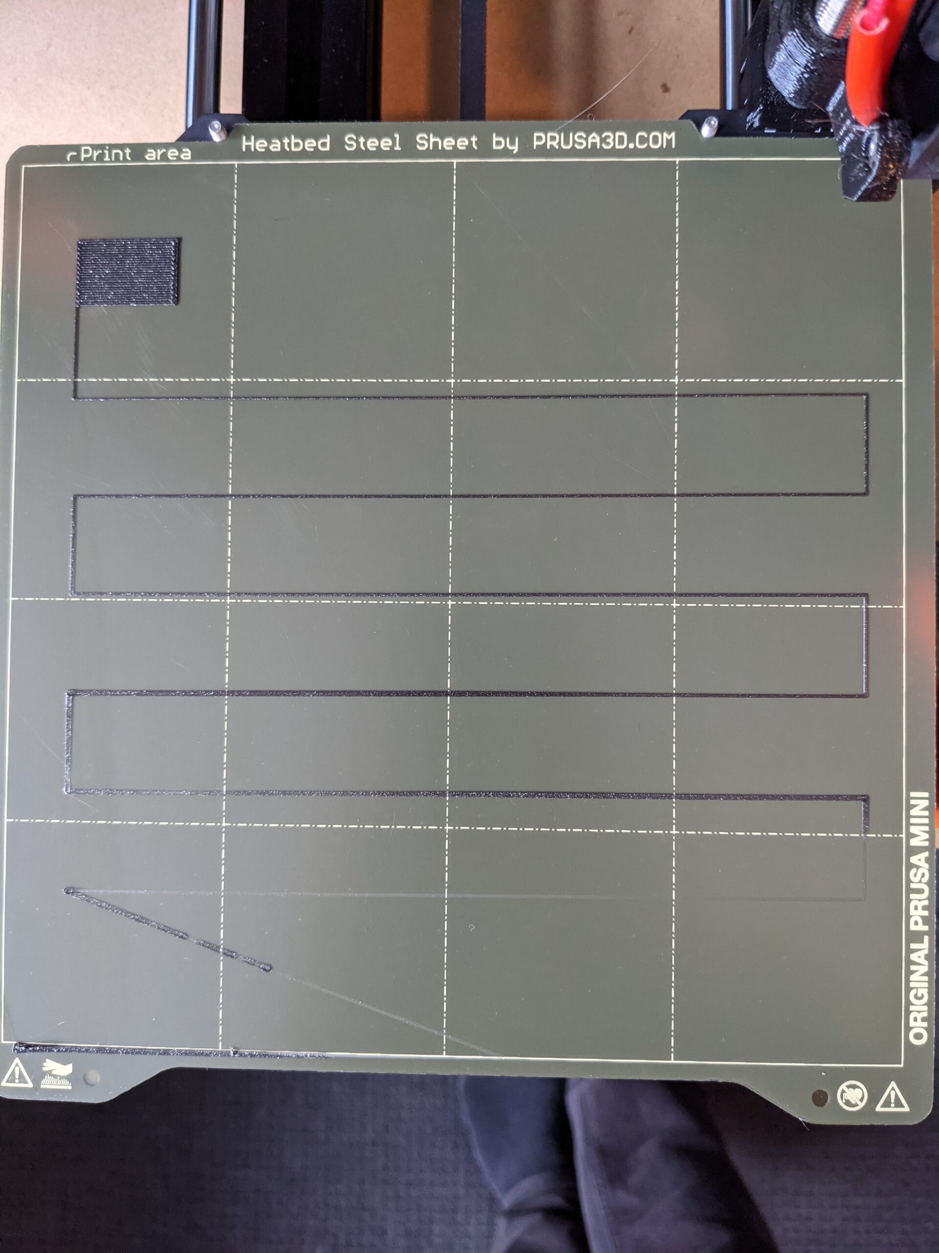
I stopped the print and did another first layer calibration, and now it seems as though the nozzle moves away from the print bed of its own accord. I've attached a photo of the results, I didn't touch the Z height all while this was printing, you can see it starts off way too close, but by the end of the print, it seems too far away.
Does anyone know what is the cause of this issue?
Cheers,
Sam
Here are some photos of my first print, for reference.


Here are some photos of my first print, for reference.
Nozzle hitting print
Typically, if your nozzles hitting the print, you have poured he Jean and the print is releasing from the bed in a while and the nozzle to hit it. the top two reasons for this to happen is a print sheet with oils or finger prints on them and A Z offset or live Z that is not perfect. I suggest that you try to cleaning your sheet a little more thoroughly or making sure you’re Z offset is absolutely perfect. Even though you’ve been successful and printing the logo, this can still happen with taller print.
Good luck.
--------------------
Chuck H
3D Printer Review Blog
post calibration
Hi Chuck,
Thanks for responding!
I can rule out sheet contamination with almost certainty. I had been wiping down with denatured alcohol, and later after I read suggestions that can leave residue, i have been cleaning with dish soap and warm water.
As for z-height calibration, I cannot say. I can get it to look perfect on the prusa logo first layer, but if i try to print any of the other models that come on the bundled thumb drive, its a total disaster. I spent some time with a Prusa support person working through the z-height calibration, and they thought it was looking good. Then I tried to print Benchy, and immediately got inconsistent lines like in my original post. Some lines on the first layer looked like the nozzle was basically hard up against the print bed, and some lines looked okay. I have been making minor adjustments to the z-axis between attempts, increasing the height from about -1.100 to -0.900 over about 6 attempts and it doesn't seem to make any difference at all as far as I can tell.
I've attached a photo of the latest attempt.

On your first photo (first post), Y-axis seems not to be perpendicular to Z-axis. As you can see there, at beginning (front of the bed) nozzle is almost smudging filament on bed (nozzle is too low). Toward the end first layer calibration, lines get less flat and finally, at rectangle nozzle is too high. Until you solve that, it makes no sense you print any real objects -you're just wasting filament and time.
After above issue is fixed, concentrate on first layer calibration. Result should look something like that:
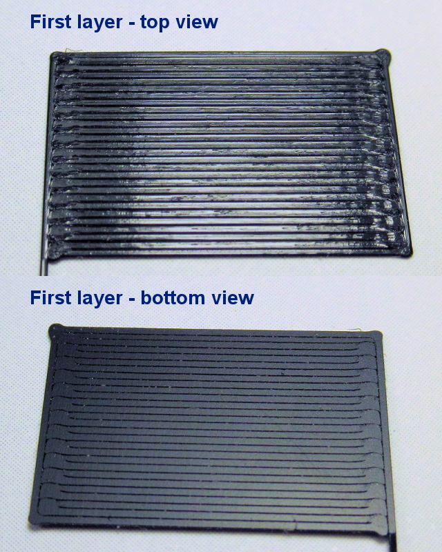
[Mini+] [MK3S+BEAR]
Poor adhesion
I can rule out sheet contamination with almost certainty. I had been wiping down with denatured alcohol, and later after I read suggestions that can leave residue, i have been cleaning with dish soap and warm water.
You can never rule that out, but it is possible your z is off instead. The filament could be wet also.
--------------------
Chuck H
3D Printer Review Blog
skew
Hi Bogdan,
Thanks for responding! I have been digging around trying to look for appropriate troubleshooting steps for this issue. I checked XZ axis skew as per prusa knowledge base and there is definitely something amiss. I made a small correction as per the article, but I found that actually the largest discrepancy was between the front and back of the print surface on the side closest to the z axis. I've attached an image. Green was where I began checking the nozzle height, and was my reference point. Yellow was a fraction of a mm lower, and red was a larger fraction lower. This result seems like the opposite of what I would have expected to find in terms of the Y axis. I would have thought that based on my first layer calibration, the nozzle should be further away at the points along the top of the image attached.
It seems possible that my steel plate is not uniform thickness either, because it gave different results if i flipped it around.
I found an a post and a github article by another user which troubleshoots some skew issues. I will try working through some of those.
I think, no print bed (print sheet) is perfectly flat -that's why auto bed leveling exists. During auto bed leveling, printer (SuperPINDA) determines flatness irregularity at 16 points on print bed. And during printing, nozzle height (Z-height) is automatically adjusted according to values found at auto bed leveling. Means, if flatness imperfection is within certain range, printer is still capable to print normally (as if print surface is perfectly flat). Flatness imperfection can be seen as combination of print bed (sheet) "bumpiness" and non-perpendicular geometry of the printer.
How much of imperfection is still tolerable by printer, where it's still able to correct those imperfections? How much is still within "certain" range? My guess is, it's about 2mm max. That is, if difference between lowest and highest point on print bed is less than 2mm, then printer should successfully compensate imperfections. That's in theory... in my opinion, difference shouldn't be bigger than about 1mm.
Now, print bed is usually flat enough and so within acceptable range. The problem starts if we add printer's geometry imperfection. Let's say, Z-axis isn't perpendicular to X- or Y-axis. Let me emphasize: it must be at exact 90° angle! If it's only 0,6° off, it will cause height difference of 2mm between both edges of print bed ( h = BedWidth x tg(angle) ). And together with print bed imperfection, we're already out of acceptable range.
So, what happens if flatness imperfection (bumpiness and/or axis skew) is out of acceptable limit? It depends on where on bed that limit exceeds... that is, if Z-axis is less or more than 90°. In extreme situation, it can happen during first layer calibration, that on certain bed area printer starts to print above print surface (in the air), or it can scrub into print surface. In non extreme situation, it can happen we don't get the same layer height at whole print surface.
I hope all above will help you find the reason for your trouble and correct it. Question: after first layer calibration, what is your Z-offset value?
[Mini+] [MK3S+BEAR]
Thanks for the thorough response! That makes sense to me. I will definitely have to test the squareness of each axis to the other two. I don't have any precise tools for that job on hand, I'll have to wait until I can get a decent square and a level.
The printer is currently set to a z offset of -0.900. This is a different value than what was set in the photo I originally posted. I can't remember exactly but i think in that photo the setting was around -1.100
I might run the first layer calibration a few times in succession without adjusting anything and compare the results just to rule out any sensor issue. If I get the same results each time then it seems likely to be an alignment problem. But your explanation seems pretty consistent with what I am seeing, so I think you're probably right.
Do you have any tips or advice on how to check for squareness?
RE: First Layer Calibration line thickness changing
You don't really need any tools... While printer is off, move the print head (X-axis) to most right and push print bed )Y-axis) fully backward -do it slowly! Then lower the print head by turning the Z shaft, so nozzle almost touches the print bed -you can put thin paper in between to prevent scratching.
Now slowly move print head toward left and observe distance between the nozzle and print bed. You guess it: it should remain the same the whole track.
Move print bed toward you, so the nozzle is in the half of print bed -watch distance between the nozzle and bed while doing that! Now move the print head from left side toward right side and watch the distance again. Repeat the same on the farthest edge of print bed.
After you've done above, you'll have pretty clear picture if some axis is not perpendicular to another. If that's the case, you'll know which axis is it and what you need to do to correct it.
[Mini+] [MK3S+BEAR]
Hi Bogdan,
I just followed the steps you outlined, and now I am even more confused, because the differences in the distances between the nozzle and the bed are imperceptible to my eye. I took some photos, and while difficult to accurately measure, there maybe be a discrepancy of a fraction of a mm between the greatest difference (bottom right and top left) and the smallest difference. Certainly nothing like the 1-2mm of difference you suggested should be corrected by the auto bed leveling.
Based on these photos do you think that my problem lies with axes not being parallel? And if so, how might you correct for discrepancies this small? The XZ skew article suggests adjusting the screws for deviations of 0.5-1.5mm, which i think is larger than what I am seeing, and adjusting the mast for differences of greater than 1.5mm which is definitely more than what I am seeing.
To further add to the confusion, it seems like the largest distance between the nozzle and the bed occurs on diagonally opposite corners.
Here is a very high res photo (18mb) of 9 points on the bed. Apologies for the size, I wanted to keep it as hi-res as possible.
https://photos.app.goo.gl/RnwqrUyWQnL8YTNa9
I appreciate the time you've taken to help me out so far. Thanks!
-Sam
As can be seen on photos, your Mini has "perfect" geometry -no need to change anything in this regard.
Maybe it's just photo perspective, but it looks to me, that you SuperPINDA is a bit too high. When nozzle is just touching print bed, measure distance between SuperPINDA and prind bed: it should be about 1,5mm. If it's smaller than that (say 1mm), then you will need quite big negative Z-offset in first layer calibration (and we know that Z-offset can't go lower than -2.000). If distance is bigger than 1,5mm (say 2mm) then there's a chance that nozzle will rub into print bed during first layer.
Maybe not important, but I noticed your hotend thermistor is not fully inserted (see here), which might lead to wrong temperature readings. As said, maybe thermistor position is not that important, but I would correct that, just to be sure. Note: be careful with those very thin thermistor wires!
After saying all above, your mini should print as expected.
[Mini+] [MK3S+BEAR]
Well, good to know I can rule out any funky geometry. One less variable to worry about 🙂
I used the centre of the zip tie method to set the superPINDA height as per the instructions. I'll try lowering it a fraction in any case and see if it makes a difference.
Good catch on the thermistor too. I'll adjust that.
Thanks again, i'll let you know how it goes!
possibly faulty superPINDA
After doing some more tests and relaying my findings to Prusa support, they think that the superPINDA sensor is malfunctioning and being affected by the heat. They are issuing a replacement, so fingers crossed that solves the problem.
Thanks again for taking the time to help me out!
It happens.
It is rare but it happens. You are doing the right thing in talking to support. Hopefully, they figure out what caused it.
After doing some more tests and relaying my findings to Prusa support, they think that the superPINDA sensor is malfunctioning and being affected by the heat. They are issuing a replacement, so fingers crossed that solves the problem.
Thanks again for taking the time to help me out!
--------------------
Chuck H
3D Printer Review Blog
PINDA check
@smccusker
Going through the same issue myself. i do, however, have a MINDA instead of the new SUPERPINDA.
if you can, try connecting your printer to Pronterface (via micro usb to usb. Should show up as COM3) and running G29 or the Mesh Bed levelling through the controls.
Then post the coordinates here
Here's what mine looks like:
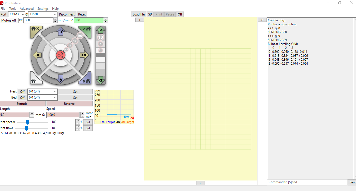

Should at least tell give you an idea of what the PINDA is reading... specially when in your pics there's hardly any height difference.
Ah awesome, good to know for the future. Cheers!
RE: First Layer Calibration line thickness changing
I am having the exact same issue with the first layer calibration on my new Mini. My calibration looks almost exactly like your first picture and support is suggesting it might be a bad SuperPINDA probe and sending me out a new one. Did this end up resolving your issue?
After doing some more tests and relaying my findings to Prusa support, they think that the superPINDA sensor is malfunctioning and being affected by the heat. They are issuing a replacement, so fingers crossed that solves the problem.
Thanks again for taking the time to help me out!
RE:
After a lot of back and forth, it was finally finally resolved. I'm not sure of the exact cause, but I suspect I over tightened the Z axis motor assembly, and it was causing the bearings to bind up. Because it wasn't moving completely freely, the auto-calibration was complete trash. Completely disassembling and reassembling the z-axis assembly fixed the problem, and I've been running the printer flawlessly for months since then. Hope you can sort out your issue!
I am having the exact same issue with the first layer calibration on my new Mini. My calibration looks almost exactly like your first picture and support is suggesting it might be a bad SuperPINDA probe and sending me out a new one. Did this end up resolving your issue?
After doing some more tests and relaying my findings to Prusa support, they think that the superPINDA sensor is malfunctioning and being affected by the heat. They are issuing a replacement, so fingers crossed that solves the problem.
Thanks again for taking the time to help me out!