Bulging corners
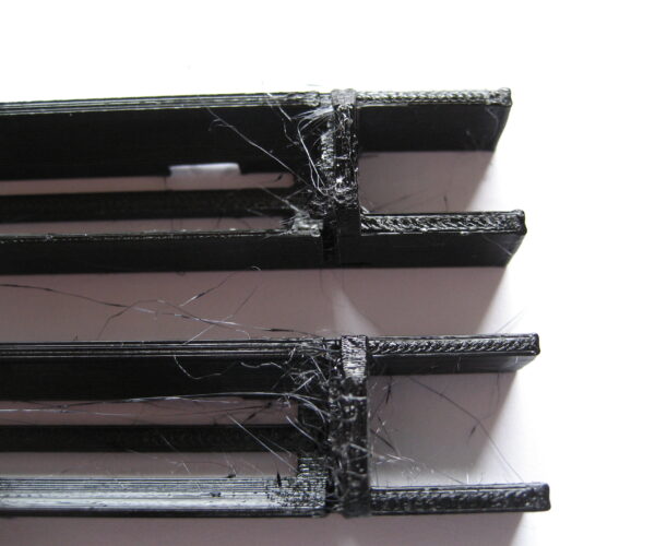
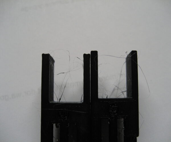
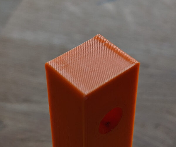
Curious if anyone else sees this on their prints:
The above is the reason why all prints come out undersize, the dimensions are typically correct (+/-0.05mm) when measured between corners, but when measuring between wall centres it reads 0.1-0.15mm less. Speed for small perimeters is Prusa Slicer default 25mm/s, so not super fast.
Any ideas how to fix this? Slow it down even more in the corners? I've done extrusion calibration and lowered the extrusion multiplier to 0.95, so I doubt it's related to extrusion, it just seems to overshoot the nozzle placement on corners and then corrects to a position which is too close to the body, causing undersizing.
RE: Bulging corners
have you tried printing at a lower speed?
Stock MK4S with FW 6.2.6
RE: Bulging corners
I should have been clearer on my post that my efforts are related to prints at high speeds made to make production manufacturing viable from a time and expense basis. Lower speeds show much better results.
Interestingly, I did make some progress yesterday. I have been using an eSun black PETG filament and in experimenting yesterday I found that an M900 K setting well higher than the K0.20 default value (Prusa PETG w/ 0.40mm nozzle) makes a difference. I have not fine tuned it but I at least can see differences which is hopeful.
RE: Bulging corners
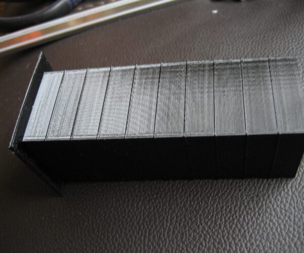
You're on the right track. Those "dog one" corners are exactly what linear advance wa intended to address. It evens the flow as the nozzle changes speeds. Here's a test piece showing the extremes:

This test piece uses the old Linear Advance 1.0 values. Newer values will typically be below 1.
and miscellaneous other tech projects
He is intelligent, but not experienced. His pattern indicates two dimensional thinking. -- Spock in Star Trek: The Wrath of Khan Unfortunately,…
RE: Bulging corners
Hey Bob,
I'd seen your tower in another post or your blog and figured I would create something similar for my machines for LA 1.5. I use so many different filaments it will be nice to have something to run to set that value for each filament.
I was stuck in the mindset that I would be well below a value of 1.0 somewhere in the range I had seen people trying for PETG and the Prusa default values, and so wasn't getting why I wasn't seeing any measurable differences in my test prints. Cheap filament and not trying a big enough K value slowed me down (well OK that AND the fact that for half a day I was trying values that had two decimals ... K0..3, for example. Apparently firmware doesn't like two decimals...lol).
Thanks for the encouragement !
RE: Bulging corners
Here is my version of an @Bobstro Linear Advance Tower. This was run on a Prusa Mini with Prusa PETG @MINI settings for 0.25 Draft settings. The only real change I made was dropping minimum layer print time to 5 seconds to keep speeds up.
What is interesting is that this shows that even the very highest levels (corresponding to K0.5 to K0.55 or so) are just getting to a good corner. I need to print a new tower that goes up to K0.7 or K0.8 to see how those look.
I've got my tower set up so that every layer is a higher K value. The values printed on the tower DO impact the quality of the corner so it might be better to print without the lettering, but kinda nice to have it.
I have not run the tower at lower speeds but I would expect different results for different speeds to do constant friction coefficients and volumetric issues. A physicist or materials engineer might offer some input but for me I am using this function to help prints at high speeds hence why I ran at Draft speed levels.
Nice way to make this adjustment.
RE: Bulging corners
If you read Prusa's analysis of how they have implemented 1.5 its changing in every firmware release right now; and to date, with 3.9.1, I can't get a good corner in PET. Even running a good cal target, things aren't making any sense, so I'm thinking LA is broken in the current firmware.
RE: Bulging corners
Ahh, I am still on 3.9.0 on my MK3s so perhaps I will hold off on updating those. I have not run this tower on the MK3s only on the Mini and I don't know how Mini FW status compares to the MK3. I will try the tower on the MK3s shortly and see if I get decent results. I do print PETG every day on my MK3s and get good enough corners for what I'm producing.
RE: Bulging corners
Oh finally some activity in this topic 😳
Btw Prusa's support couldn't suggest anything and I must've talked to at least three different people. Mind you this was bought as an assembled kit.
What speeds are people testing this on? I've only ever ran PLA at default 25mm/s and I reckon that isn't really pushing it hard. Dropping the speed to 20mm/s changed absolutely nothing.
RE: Bulging corners
Hey @tompjagiello, nice to see OP.
So for me I am trying to solve the corner issue on my MINI with a 0.4mm nozzle and using their default draft speeds which are 55 and 40mm/s for perimeters and external perimeters, respectively. I have not yet tried on my MK3s or at lower speeds and there may be firmware difference in the LA1.5 implementation, I don't know.
I am running current scenarios on a black eSun PETG and am seeing K values needed at considerably higher values than default Prusa K values, no doubt due to the cheap filament.
RE: Bulging corners
Ah, I missed Rick's replies, sorry! One thing important to keep in mind when calibrating Linear Advance: Use high perimeter speeds. LA doesn't really kick in until there's a significant difference between the slowest and fastest segments of an extrusion. In my calibration test tower above, I had to use 60mm/s or higher to get the "dogbone corner" effect. Be sure to set external perimeter speeds to match as PrusaSlicer defaults to slow speeds for these features. You might also want to use a SPEED base profile or roll your own with more aggressive acceleration and jerk values to highlight the differences.
and miscellaneous other tech projects
He is intelligent, but not experienced. His pattern indicates two dimensional thinking. -- Spock in Star Trek: The Wrath of Khan Unfortunately,…
RE: Bulging corners
Yeah, I think Bob is spot on, you should run at high speeds to see the biggest impact possible. I am running faster than SPEED setting by using a DRAFT setting which also has higher layer height (.25 vs 0.20). I would emphasize for anyone wanting to replicate that you make sure to adjust your cooling setting minimum layer time if you use a model similar to mine or Bob's from 20 seconds down to 5 or something to ensure you get full advantage of the higher speeds.
I created a 2nd tower with K values ranging from 0.4 to 0.95 or so. For the Black eSun PETG with my settings it seems that a K value around 0.59 or so is best on this model. This compares to the MINI default PETG value of 0.20, so quite a difference.
Now I will have to run one of the parts I produce with this new K value and see if I get better results or if I also need to tweak some retraction settings or something.
RE: Bulging corners
So some interesting results when I printed the part that was having corner issues on my Mini. Definitely changing the K value from K0.20 (default) to K0.59 had an impact on the corners. It did not, however fix some other issues with stringing etc, which I really did not think it would, but, you know, hoped might.


As you can see the end corners are significantly better. As are the corners around the vertical "slot". The stringing snarl and blobs are about the same. Please note this is a print at high speed (standard Mini draft setting) with an extremely stringy filament. I know I can print slower and may need to alter retraction and temp to fine tune. Just trying to show that adjusting the LA1.5 value had a large impact on bulging dog-bone corners.
RE: Bulging corners
Here is the same part printed with the same filament on a MK3S using Draft (0.3 layer height) settings.
You can see the MK3S has better corners to begin with (by better I mean less dog bone...actually they may be a little too rounded. And has considerably less stringing and blobs. The MK3S is suitable for what I do with this filament (I typically use a different filament that I get better results from but supply chains are...you know...COVID). Interestingly I noticed that the MK3S default draft speeds are lower than the Draft Mini (perimeters are about 5mm/s slower) but have a wayyyyy wider external perimeters extrusion width, a whopping 0.6mm versus 0.45mm.
I will play around with retraction settings on the Mini as the bowden is probably impacting that a little as well as try a different filament. I at some point will try the Linear Advance Tower on the MK3S's as well, just to see what different values are achieved.
RE: Bulging corners
How does one use these Linear Advance Calibration towers? Are they available anywhere with the corresponding g-code to adjust the k value in regular intervals?
Prusa Mini FW6.2.4
RE: Bulging corners
@teachtheprints
As far as I am aware it is not possible to configure Linear Advance on the Mini at the moment. As often happens, the threads has become confusing because many users have both MK 3 and Mini's and the lines blur between which printer is being discussed. 😀
RE: Bulging corners
@gordon-w - hey gordon, no I can confirm that you CAN adjust Linear Advance (1.5) on the Mini. The towers I printed shown above were on the Mini as were the parts other than the identical parts from a MK3S shown for comparison. The adjustment is made in the filament custom g-code section. And changing the values definitely has an impact. For the filament I was using the K factor was much higher than defaults, so took awhile on the towers for it to show up.
RE: Bulging corners
@teachtheprints - I'm not aware of a standard tower out there for calibration, at least not that I saw. I made mine similar to @bobstro's tower that I had seen in pictures. 100mm high 30mmx 30mm square with walls at 1.64 mm to match the Mini's recommended 4 line walls at the 0.25mm Draft setting. I'm happy to throw that up in an STL if desired. You want high perimeter speeds to notice the impact of the K factor so I was running a the Draft setting with PETG filament. Make sure you drop your minimum layer time in the cooling section to 5 seconds or something to keep those speeds up.
As for g-code what I did was the following: In the Custom g-code of your Print Settings (not the filament section where you will ultimately place the K factor for each filament) Before Layer Change I used the formula:
;BEFORE_LAYER_CHANGE
M900 K{(layer_z + 5)/200}
G92 E0.0
;[layer_z]
This changes the K factor for every single layer and each 10mm on the model will increase by 0.05 (the 5 in there is just to start it out the way I wanted).
You can check your created g-code to ensure it is working.
Cheers!


