Part of layer is missing
Hello,
I know there are similar topics out here but i couldn't still fix the problem.
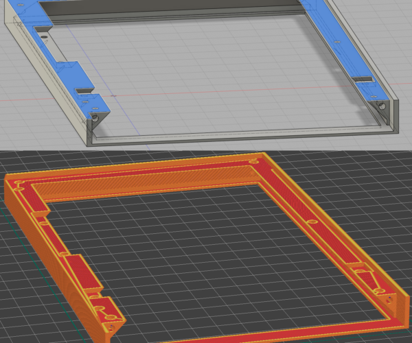
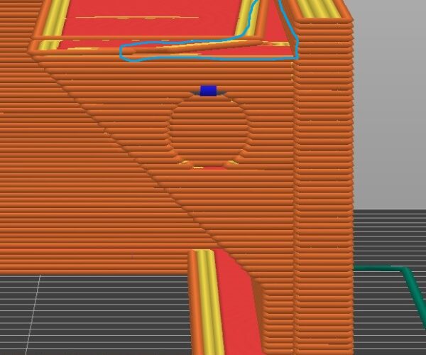
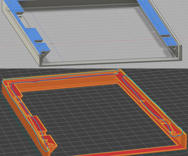
Part of the layer is missing, with similar model this problem does not exsist.
Best Answer by Neophyl:
I don't use fusion so cant really advise on how to fix it in that software but good on you for wanting to treat it as a learning process. That is far more useful than just accepting my fixed version.
I suspect that the top surface has a slight bow to it or other angle. I'd double check any angles you might have. Its also possible that the bottom surface itself is very slightly tilted, that would have the same effect on upper surfaces once the bottom is placed flat to the bed. When its exported then where the holes go through that surface some verts on one side of a hole will be slightly higher than others.
It only has to be off by a tiny fraction of a mm if the boundary falls on a layer. For example if you change your layer height to 0.15 instead of 0.2 then the issue magically goes away as you are changing where the layer boundary lines are and the verts no longer fall either side. They are all falling inside a single layer.
As to how I fixed it, after exporting your model as a stl I loaded it into Blender. Blender is very good at manipulating meshes (once you have a bit of practice). I then went into edit mode and selected vertices mode so that I could select individual points. I then selected every point on the non flat surface and used scale in Z=0. That in effect in Blender makes all the verts go to the same Z height. Instant flat surface. I also did the same to the bottom to make sure it was flat and parallel to the upper surfaces.
RE:
Either your model isnt perfectly flat to the print plater or that surface is not perfectly level. Its in the PS FAQ https://help.prusa3d.com/article/faq-prusaslicer_1789 Q: Strange pattern on a flat surface
As the slicer is splitting things into discrete layers then if vertices in the model fall into a small range then some cab be above the cut off point and others below for a layer. That leads to the islands you have noted. Given they are next to holes then I would surmise that verts in the holes aren't perfectly level. When I get home I'll take a look at your 3mf file and export the model to Blender and see if I can fix it for you.
RE: Part of layer is missing
Here you go. Attached zip with fixed model in both 3mf and as a stl.
RE: Part of layer is missing
Wow, thanks a lot @neophyl !
The easier solution would be for me to just accept this, but i would actually want to try and learn something out of this.
I would understand the vertices thing if the two holes meet then it get's "bugged", but the island also exist where there is only one hole.
First question would be if you or someone else has any idea if it is possible to fix it in fusion (in model itself)? Not sure if i could share the model if necessary as i use the free version of fusion. It lets me export to .f3d.
Second question, what steps did you take to fix it for me at this point ?
RE: Part of layer is missing
I don't use fusion so cant really advise on how to fix it in that software but good on you for wanting to treat it as a learning process. That is far more useful than just accepting my fixed version.
I suspect that the top surface has a slight bow to it or other angle. I'd double check any angles you might have. Its also possible that the bottom surface itself is very slightly tilted, that would have the same effect on upper surfaces once the bottom is placed flat to the bed. When its exported then where the holes go through that surface some verts on one side of a hole will be slightly higher than others.
It only has to be off by a tiny fraction of a mm if the boundary falls on a layer. For example if you change your layer height to 0.15 instead of 0.2 then the issue magically goes away as you are changing where the layer boundary lines are and the verts no longer fall either side. They are all falling inside a single layer.
As to how I fixed it, after exporting your model as a stl I loaded it into Blender. Blender is very good at manipulating meshes (once you have a bit of practice). I then went into edit mode and selected vertices mode so that I could select individual points. I then selected every point on the non flat surface and used scale in Z=0. That in effect in Blender makes all the verts go to the same Z height. Instant flat surface. I also did the same to the bottom to make sure it was flat and parallel to the upper surfaces.
RE: Part of layer is missing
Post the f3d file. It‘s the one fusion puts everything in you need. I’ll take a look.
(if you want more export options, go to the web interface, you can select the file inside fusion and access it from there. From there pretty much all formats are also available when using the free version. But for sharing with other fusion users f3d is fine)
If at first you don't succeed, skydiving is not for you.
Find out why this is pinned in the general section!
RE: Part of layer is missing
This seems to be accurate and removes the issue (i changed first layer to 0,24 - no more island).
It only has to be off by a tiny fraction of a mm if the boundary falls on a layer. For example if you change your layer height to 0.15 instead of 0.2 then the issue magically goes away as you are changing where the layer boundary lines are and the verts no longer fall either side. They are all falling inside a single layer.
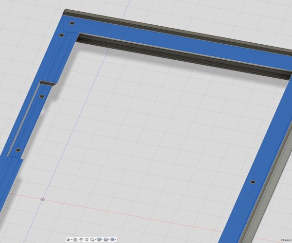
But as you can see on the pictures the selected area has no islands, what i've learned so far is that if there is any slight tilt or height differences fusion will show it with a line where the hop happens. When i modelled eveything was done at 90 or 45 degrees.
Here is the design (pw: "bracket"):
RE: Part of layer is missing
One thing I noticed in the f3d file is that if you click on the top surface of the frame and then shift-click on the top surface of the cutout with the two holes on the right, it shows "2 faces | Angle 0.0 deg" in the lower right as opposed to the actual distance, which means the two surfaces are almost parallel, but not quite.
After Extrude355, you're left with two faces for the top and bottom surface of the cutout. If you delete one of them right then and not in Extrude356, now you get the correct distance shown, not the Angle 0.0 deg message. As a consequence, you'll need to redo Extrude422 with the new face, and I'm not sure what DeleteFace15 does.
Or perhaps simpler, in Sketch 254 replace the two lines that form the top and bottom of the cutouts respectively with one line each, so you avoid creating the two faces on top and bottom in the first place.
Not sure that is indeed the cause of the issue you're seeing but it seems very likely.
Formerly known on this forum as @fuchsr -- https://foxrun3d.com/
RE:
Selecting the two faces as descibed wont show any angle for me.
There was a thing where there was two faces on the cutout, but i removed one of them, i cant find the action at the moment.
Editing sketch254 as described will create vertex issue with next extrude and i don't know how to fix that one. :/
RE: Part of layer is missing
At least now i know what to look for in the future, but it's really odd that an angle was even created.
Temporary fix is changing the first layer height from 0,2 to 0,24.
One more thing that was not mentioned is that Cura managed just fine to do the slicing without any islands.


