Mk4 Display Cable to short for the Prusa Original Enclosure?
I'm trying to get the cable routed to the front and I don't see a way to make it reach. I've tried routing around the left side (waaay nope) and routing through the bottom notches. Even just holding the front up and using an impossible in normal operation direct path seems too short.
How are others making this work? A photo if you have one would be super useful!
Thanks.
RE: Mk4 Display Cable to short for the Prusa Original Enclosure?
I swapped from MK3 to MK4 and struggled with the cable. At first I thought it would not fit.To me it an extra few cm would help. I made it work
- follow the guide for the enclosure with the MK3. The cable runs from the motherboard , under the printer to the hole in the front of the enclosure
- start by not cable tying the ribbons
- don’t twist the ribbons
Once you have it fitted work out how to cable tie the ribbons.
Sorry no photos now that it’s in the enclosure I don’t want to take it out
RE:
At first i detached the display cables from the original position on the inside of the left frame strut all the way to the electronics box when I removed the PSU cables from the frame. I then ran the display cables from the electronics box along the left strut on the outside of the frame to keep them away from the belt and to avoid them being crushed by the vertical frame. This gave me a bit more room, but they were still a bit short.
Then I used the Squash Ball Mod to get more clearance under the printer. After that I could run the cables diagonally under the printer and they wouldn't get in the way. The Squash Ball Mod also makes your printer a lot quieter. I put a 20 mm thick mat made from compressed rubber pieces under the enclosure to eliminate the resonances. The printer inside the enclosure is really quiet now. I hope this helps. 🙂
RE: Mk4 Display Cable to short for the Prusa Original Enclosure?
I also really hope that somebody comes up with a solution like the Display Cable Quick Release for the MK3S, which is great. The cables and the connectors are different on the MK4 and I could not find the connectors anywhere.
RE: Mk4 Display Cable to short for the Prusa Original Enclosure?
Could someone post a picture of the MK4 display cable and connector?
RE: Mk4 Display Cable to short for the Prusa Original Enclosure?
I’ve asked support for the manufacturer and model of the connector. Its an unusual connector
RE: Mk4 Display Cable to short for the Prusa Original Enclosure?
It also looks to me like it could be easily damaged if you detach and reattach it too often. It does not look as sturdy as the connectors on the MK3S.
RE: Mk4 Display Cable to short for the Prusa Original Enclosure?
The end connectors on the MK4 LCD cable look to me like 'MicroMatch' series from TE Connectivity. The stock MK4 cable has 24 conductors, rather than the 20-conductor cables on the MK3 series printers. I made my own MK4 LCD quick-release cable using TE Connectivity Part# 9-215083-4 for the xBuddy board and LCD ends. I agree those don't seem suited for repeated pulling, so I used a bigger 24-pin header/receptacle pair for the disconnect point in beteween.
The PowerFail connector on the xBuddy board is from the 'CLICKMATE' series. I bought a pre-made "CLICKMATE 2 CIRCUIT 600MM" cable, Molex Part# 0151350206 to alter the stock Enclosure Quick-release printer-side cable to work with the MK4. Since the xBuddy board powerfail connector uses only one of its two pins, I clipped the unused wire from the cable I bought.
Hi
I have purchased the parts from Digi-Key thank you for the part numbers however I cannot for the life of me find the female mating parts can you give me the part code for the bigger male/female receptacle pair please
Regards
Kerry
RE:
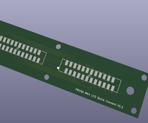
I could not find one either. I don't believe there is a crimp micromatch female. I could only find PCB mount versions. I'm in the process of creating a PCB with two female connectors.
The idea being the orginal cable mates to one of the female connectors and then you have a short cable from the other female to the display LCD. Hopefully you can then use the orginal LCD cable without having to re-route it.
I made an error on the orginal PCB so did a second version, and then the supplier sent me someone else's PCB so now they are redoing it. The PCBs are 5 for $11
I also have a 3d printed enclosure for the PCB.
I'll post details once its working.
RE:
...the part code for the bigger male/female receptacle pair please
I used:
24-conductor ribbon cable socket: 3M Part# 4624-6001
strain-relief for above: strain-relief
24-conductor ribbon cable connection header: ASSMANN WSW Components Part# AWH 24G-E202-IDC
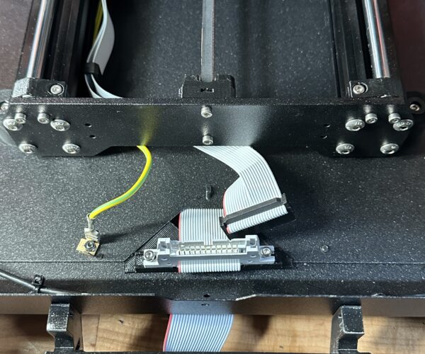
Using a PCB for a quick-disconnect point will allow using the original Prusa LCD cable. I was concerned that the MicroMatch connectors might not stand up to repeated tugging, so went with the larger connectors that offer a strain relief. I kept the factory LCD cable for backup, and tried to route my new cable through the MK4 frame as closely the same as the original. I've not had any of the LCD problems that others have described on the forum, but it sounds like cable routing is one possible cause of those. Finally, I also made a (ugly) provision to quick-release the green/yellow bonding cable, as Prusa seems to have taken care to make a separate plane on the LCD board for that. Maybe something to do with future touch-screen control, don't know but easy enough to take care of. The picture doesn't show the short bonding wire that I added to connect from beneath the enclosure to the LCD board.
RE: Mk4 Display Cable to short for the Prusa Original Enclosure?
...the part code for the bigger male/female receptacle pair please
I used:
24-conductor ribbon cable socket: 3M Part# 4624-6001
strain-relief for above: strain-relief
24-conductor ribbon cable connection header: ASSMANN WSW Components Part# AWH 24G-E202-IDC
Using a PCB for a quick-disconnect point will allow using the original Prusa LCD cable. I was concerned that the MicroMatch connectors might not stand up to repeated tugging, so went with the larger connectors that offer a strain relief. I kept the factory LCD cable for backup, and tried to route my new cable through the MK4 frame as closely the same as the original. I've not had any of the LCD problems that others have described on the forum, but it sounds like cable routing is one possible cause of those. Finally, I also made a (ugly) provision to quick-release the green/yellow bonding cable, as Prusa seems to have taken care to make a separate plane on the LCD board for that. Maybe something to do with future touch-screen control, don't know but easy enough to take care of. The picture doesn't show the short bonding wire that I added to connect from beneath the enclosure to the LCD board.
Thank you, I already ordered my other bits from Digi Key so I will add these next time I have an order.
Regards
Kerry
RE: Mk4 Display Cable to short for the Prusa Original Enclosure?
I could not find one either. I don't believe there is a crimp micromatch female. I could only find PCB mount versions. I'm in the process of creating a PCB with two female connectors.
The idea being the orginal cable mates to one of the female connectors and then you have a short cable from the other female to the display LCD. Hopefully you can then use the orginal LCD cable without having to re-route it.
I made an error on the orginal PCB so did a second version, and then the supplier sent me someone else's PCB so now they are redoing it. The PCBs are 5 for $11
I also have a 3d printed enclosure for the PCB.
I'll post details once its working.
Good Idea, I considered mounting them to a pcb including the earth wire too
RE: Mk4 Display Cable to short for the Prusa Original Enclosure?
Thanks I have a connection for the earth wire using a tab
RE: Mk4 Display Cable to short for the Prusa Original Enclosure?
Nice PCB Board Michael
RE: Mk4 Display Cable to short for the Prusa Original Enclosure?
Thanks I have a connection for the earth wire using a tab
I very much would be interested in purchasing a populated PCB from you Michael but it would need to be shipped to the UK please
RE:
Hello
Thank you for this post!
I want to do like ssmith here has done, with the addisjon of a longer cable, but I'm not sure how long I can extend the cable and still get good signals?
I've placed my printer in a kitchen cabinet, so my printer basically sits on the floor, so I would like my control panel at bench height.
That would mean a +1 metre cable length.
Would this be the right cable: https://www.digikey.no/en/products/detail/assmann-wsw-components/AWG28-24-G-1-300/2272557
Terje
RE: Mk4 Display Cable to short for the Prusa Original Enclosure?
I would be willing to pay something like 20 USD + whatever shipping cost to Germany for such a kit as well. 🙂
I very much would be interested in purchasing a populated PCB from you Michael but it would need to be shipped to the UK please
RE: Mk4 Display Cable to short for the Prusa Original Enclosure?
@michael-2 would you be willing to share the pcb layout ? Otherwise if you intent to sell (un)populated boards or pcbs (to Germany), please let me know
RE: Mk4 Display Cable to short for the Prusa Original Enclosure?
Hi
I abandoned it.
It worked but wasn't reliable. There's no specs on the LCD ribbon cable. I guessed is the LCD wasn't getting enough power and maybe I needed to make the power supply tracks on the PCB larger. Also maybe there was some cross talk between signals e.g. there were some grounds between signals in the ribbon cable to avoid crosstalk. All a total guess without any specs.


