RE: Ideas to make enclosure for XL Multi Tool
Caption reads: “pondering what else I can design and print for my 3d printer now I’ve almost finished it all”
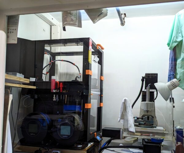
The view from my work bench.
Appreciate you bringing us along for the journey. I’ll miss it when you’re fully finished!
RE: Ideas to make enclosure for XL Multi Tool
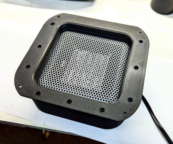
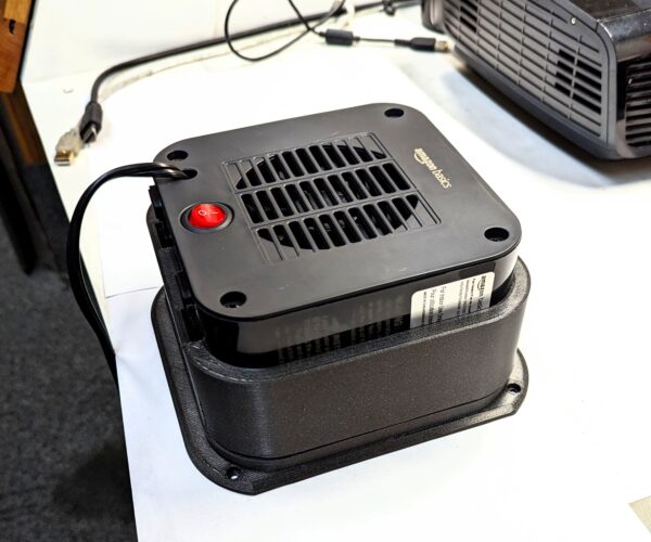
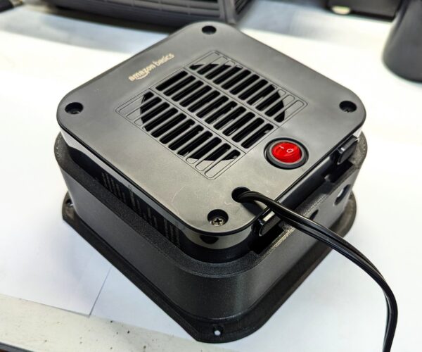
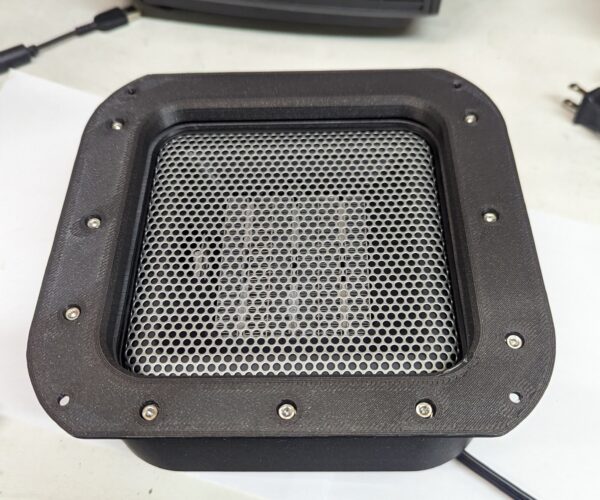
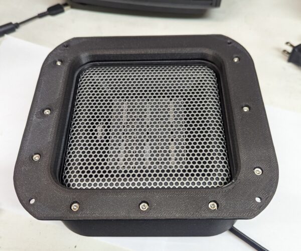
After messing around for a few days with the PTFE issue I was able to get a few parts printed for the enclosure heater mount. The mount is printed in Prusament Galaxy Black ASA.
Due to the complexity of the many supports it would take to print it in one piece I opted to print it in two parts. The base and the heater housing. In two parts no supports were needed just a 20mm brim. I will actually use M3 inserts and M3 hex heads to assemble the parts. Before assembly of the 2 parts I will paint each mating surface with acetone to glue them together. After the screws are tightened down the parts will fuse together.
I still have to print the gate to close off the opening when the heater is not in use. I also have to print the inside mounting plate.
This pic is of the side that faces the inside of the enclosure.
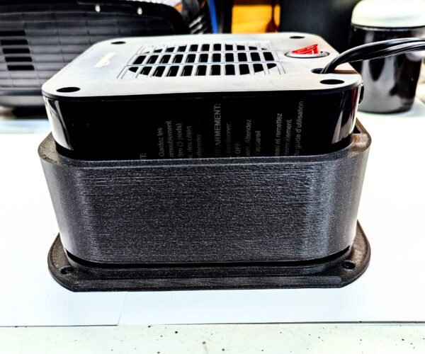
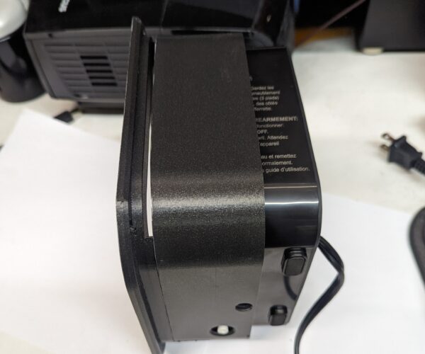
The two parts sitting on top of each other. You can see the gate slot towards the bottom of the mount. The heater just slides in the mount. It is a snug fit. It will be interesting to see how the ASA reacts to the heater. The heater has a thermostat that will turn it off after the enclosure is preheated to the correct temperature.
A few more views.
RE:
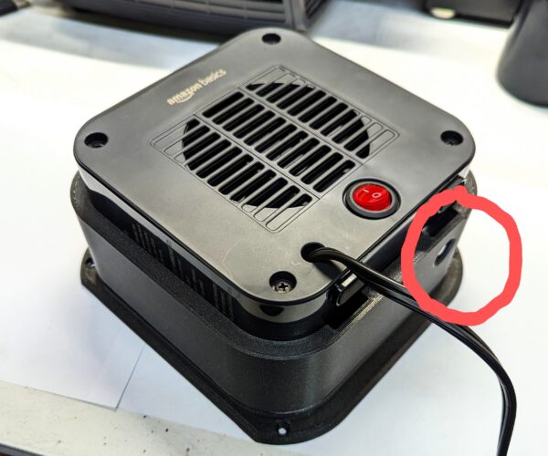
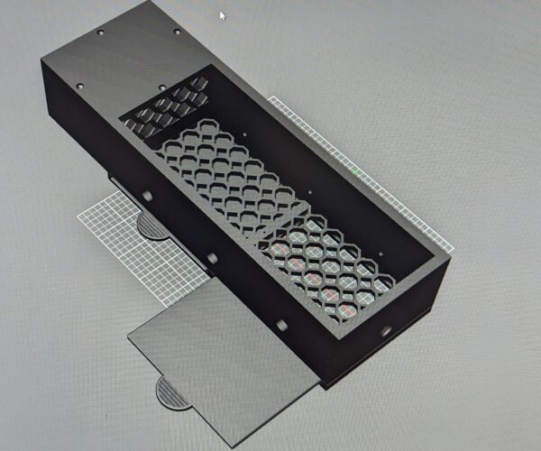
One more thing. If you look at the pic below you will see a hole for the white tip over switch. I am going to print a round thin piece of PLA that will be inserted in the hole holding the tip over switch in the on position. If the housing gets to hot the PLA will warp and release the switch turning off the heater.
That's a wrap for the week. I will be back at it next week.
RE: Ideas to make enclosure for XL Multi Tool
Caption reads: “pondering what else I can design and print for my 3d printer now I’ve almost finished it all”
The view from my work bench.
Appreciate you bringing us along for the journey. I’ll miss it when you’re fully finished!
Thanks! That's the killer thing about 3d printing! If you can dream it up and can draw it on CAD you can make it. I don't care what it is!!
RE:
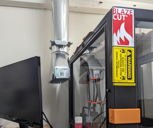
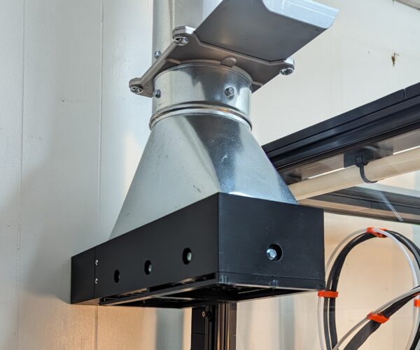
So I am back at it today. I was able to run the 4" pipe from the main exhaust system today. It took me the better part of the morning to take care of that. I am going to print a cover for the vent that will have a 2" round hookup for the printer exhaust output vent. Another project!! It will also have a outside vent so I can just vent the room itself.
I was also able to assemble the two ASA parts of the heater mount. I use M3 inserts and M3 hex head screws to assemble the 2 parts. I painted the two parts with acetone before assembly.
I will print the other 2 ASA parts later this week. I want to print the vent cover first so I can vent the room and printer while printing ASA.
RE: Ideas to make enclosure for XL Multi Tool
It will be interesting to see what this does to your enclosure temperatures with all the doors closed. Do you know where you’re planning to extract from (top, middle or bottom?). I’d imagine extracting from the top of the enclosure might be a little aggressive in reducing the temperature? Interesting to see the results!
If you remember the lower venting panel in the back has two removable gates. I am going to print a 2" vent for one of them. It will be located below where tool #1 is docked. This venting fixture will slide into that adjustable gate slot.
I took am curious about the temps inside. This will primarily be used for PLA but I will try it with higher temp filaments as well.
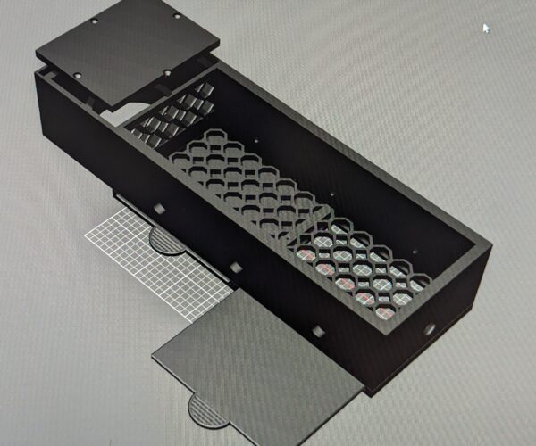
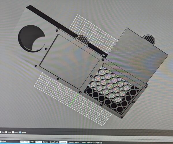
The exhaust duct cover has two isolated opening one for the printer and one for the room itself. I will post a pic of the cad itself later today.
RE:
I just started this print for the exhaust system. It will go over the exhaust return. It has the 2" round exhaust port for the printer and two closable exhaust vents for the room.
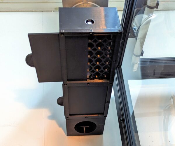
After this prints I will print the Exhaust fitting that slides in the lower venting gate opening on the back of the printer. It will go to the shop exhaust return housing. It will probably be 2 to 3 pieces. The top of the housing on the left has a compartment for activated charcoal if I need it.
RE:
I might be tempted to try bypassing the filament sensor and see if that helps. There is a thread on here somewhere about how to reduce the pressure of the sensors (it was causing issues with flexible filament) so don't know, if that heats up from the frame if the pressure increases due to metal expansion.
The other thing just to test is to try heating everything up but try removing the printer head end of the filament tube and just try a manual test pulling the filament in various combinations (no filament sensor, no large bend at the back of the printer, different filament reel bearings, moving the filament sensor down to reduce the bend at the back (you'll need to extend the wire/add extra extension connector - connectors stated somewhere on the forum again) to see what makes the difference. If you had a pressure sensor when pulling, you could even do it scientifically!
I'd be interested if the other tube made a difference too.
Look forward to hearing your findings!
I can tell you this much. I went to 4mmOD X 3mmID PTFE tube and that made a huge difference. But once I bypassed the filament sensor the prints look so much better. I have been testing it the past few days. If you know you have enough filament I would bypass the sensor all together.
I do think that the long PTFE runs (tool 1 is almost a meter and a half) and the high tension on the filament sensor is just a problem waiting to happen. I could see going with lighter springs in the sensor or having some sort of electronic sensor. This would be much better. Oh and change to larger ID PTFE tube.
You can see on tool one I bypassed the sensor with just a piece of filament. I also went with the 3mm ID PTFE tubing.
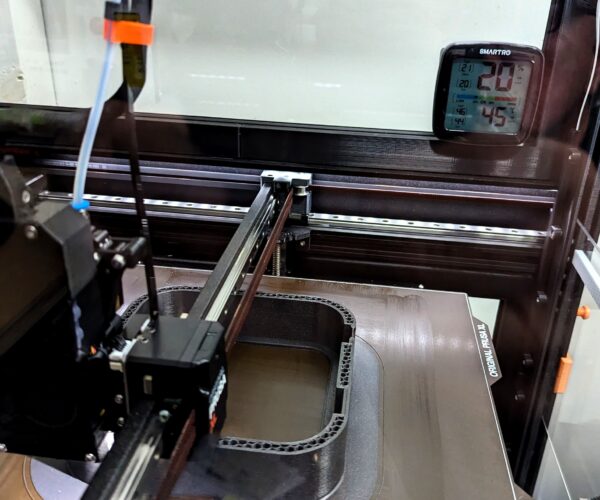
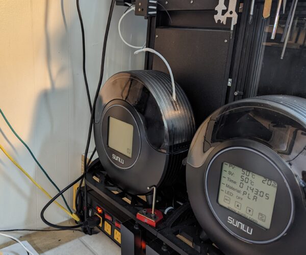
It seems that PLA prints the best at 34C to 35C. 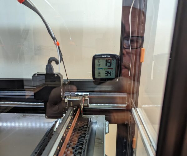
You can see how good this print looks. I am 5 hours into a 10 hour print.
RE: Ideas to make enclosure for XL Multi Tool
Those are really interesting findings. It sounds like the nextruder is somewhat stressed feeding the filament though even in normal conditions.
I wouldn’t have thought it would be too hard to source lighter weight springs - let us know if you find suitable ones.
Did you try it with the original 2/4 PTFE tube but without the filament sensors?
RE:
Those are really interesting findings. It sounds like the nextruder is somewhat stressed feeding the filament though even in normal conditions.
I wouldn’t have thought it would be too hard to source lighter weight springs - let us know if you find suitable ones.
Did you try it with the original 2/4 PTFE tube but without the filament sensors?
No I did not try the original PTFE tube. I went straight to the new 3mm ID tube. The original was just to deformed in the key areas mentioned above.
As I mentioned the PTFE runs are long and the Nextruder stretches out so far to the front it doesn't take much for the tube to develope small kinks at the wire tie and the entrance into the Nextruder. The tolerances in the tubing with the filiment are pretty tight. So those small kinks and the pressure in the sensor seems to hamper the filament flow. Especially when you add the higher temps in the enclosure.
At least that is my theory. I do know what I have changed makes a big difference. This happens over time. Right out of the box things are fine. Over time these tubes are stretching and deforming at the key point. This started on my printer after 300hrs.
RE: Ideas to make enclosure for XL Multi Tool
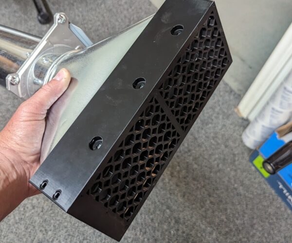
So now this is the print for the air return I did last night. It is print 1 of the 5 part exhaust air return. It is probably the best print to date on the XL. It has zero issues. The print took over 10 hrs . Of course this is PLA. When this exhaust system is done I will be back printing ASA parts. The Sunlu PLA I am using likes the enclosure temp of 34C-35C. Zero warping.
RE: Ideas to make enclosure for XL Multi Tool
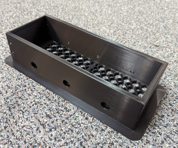
Here is what the 1st exhaust return part looks like. There is a small housing for the printer vent that attaches to the back of this part. You can see the mounting holes for it. That box has tabs that slide into this part to attach it. Excuse the dusty finger prints!
RE: Ideas to make enclosure for XL Multi Tool
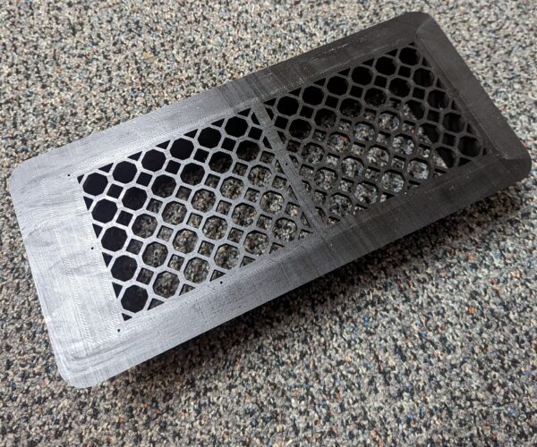
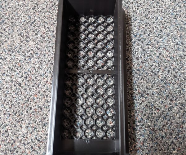
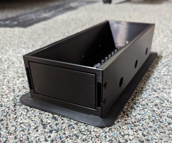
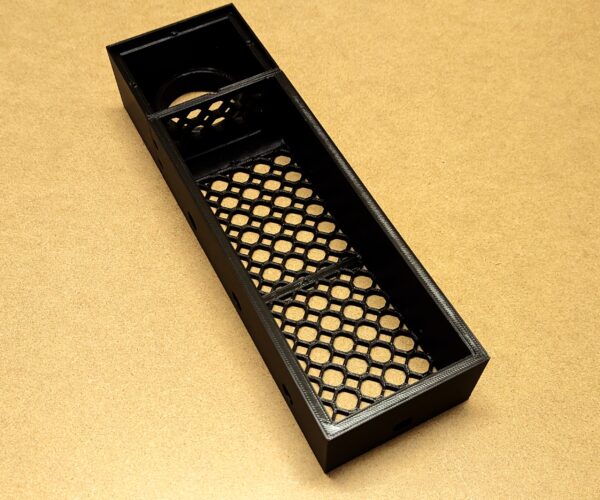
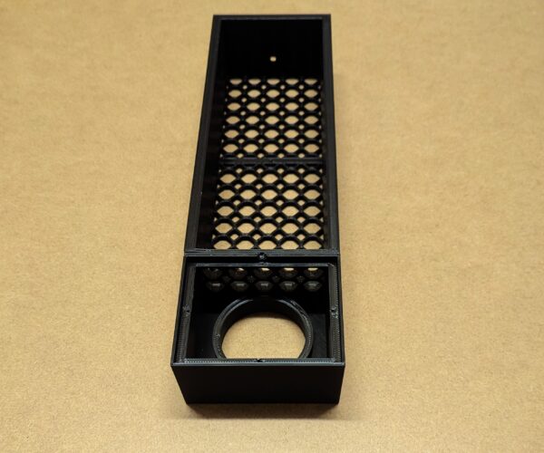
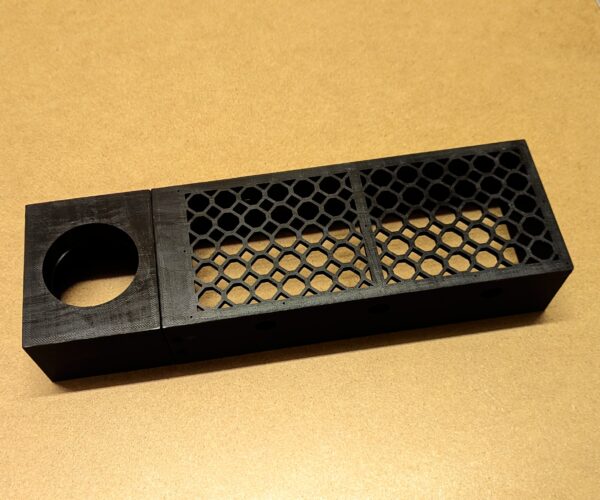
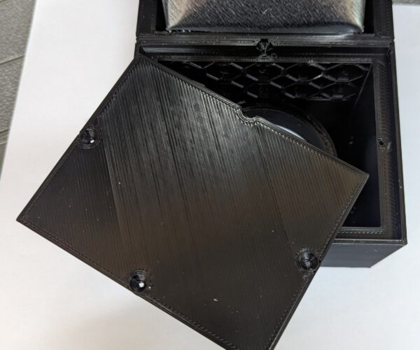
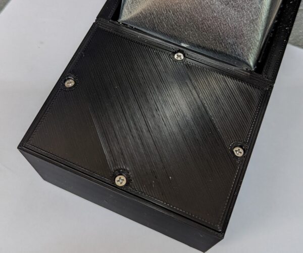
I finished part 2 of the exhaust here are some pics.
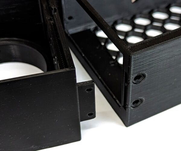
Here is the pic of the two parts together. Part 2 is the connection part from the exhaust to the printer.
The second part has a tongue in the front and back that slides onto a groove on part one. Then screws hold it in place. There is a printed screen that goes over the hole of part 2 to add activated charcoal if needed .
RE: Ideas to make enclosure for XL Multi Tool
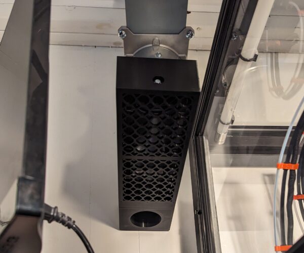
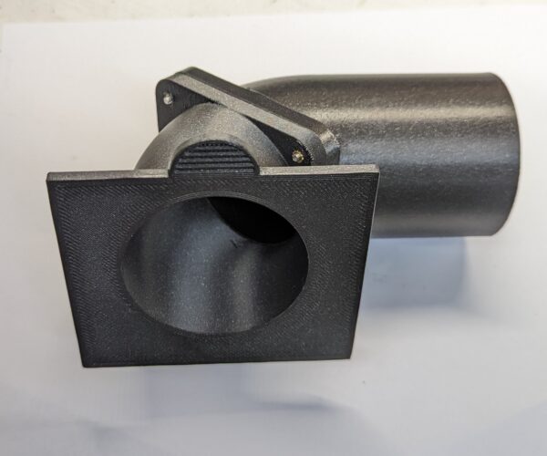
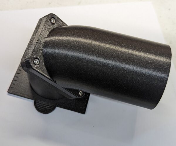
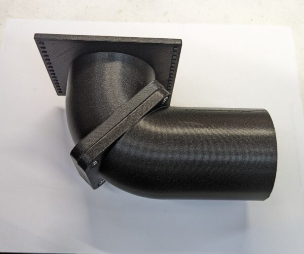
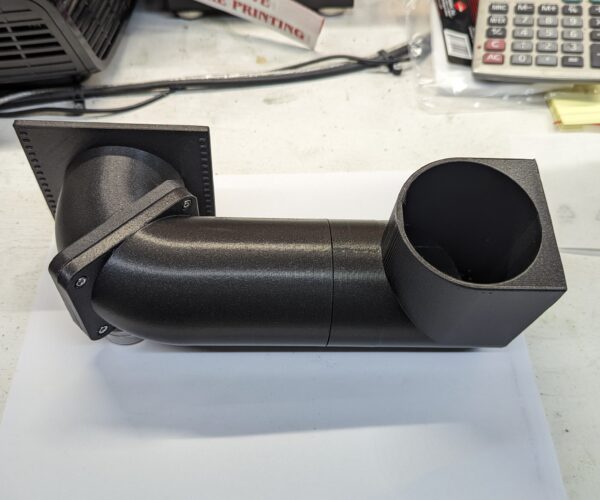
Okay so I haven't slowed down. Just busy in the shop. Had some time to design some of the parts for the direct exhaust from the back of the printer. These are the first two parts assembled. Both are printed out of ASA.
The more I print ASA the more I like it. It has a very nice smooth and hard finish. It also seems very tool friendly compared to other filaments.
There will be 4 more parts to print then the direct exhaust from the printer will be done.
RE:
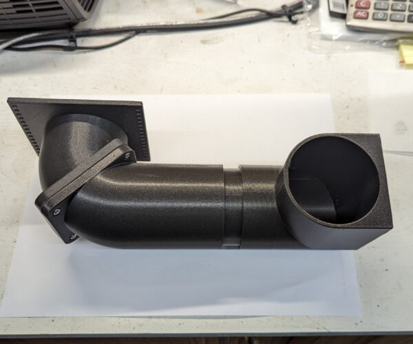
The 3rd of 6 parts finished printing today. Still have about 13 hrs of printing parts for the exhaust and that will be done.
Then I have 2 parts for the heater to print. Then I can start on other things besides the enclosure. I am still planning on releasing the STLs but it has been put on the back burner for a little while due to a heavy work load at the shop.
I made the third part telescopic so I will be able to line the up pipe and fan with the exhaust return above.
