Re: Quieting the R3 blower design
Version 1 completed and operational!
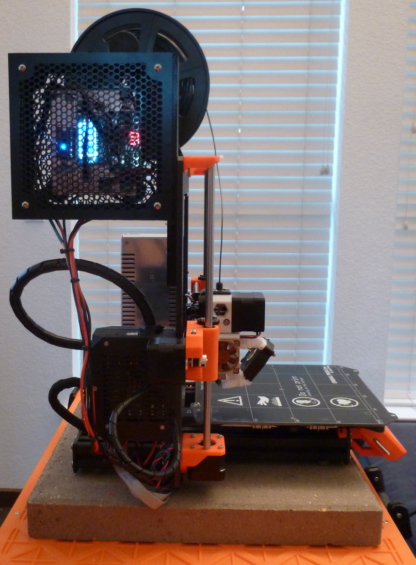
If someone has ideas on better cable management, I'm all ears. It's my first attempt, but it seems to work.
In addition to ventilation, the honeycomb also allows me to read the frequency and duty cycle on the internal LCD display, should I wish to. 😀
Re: Quieting the R3 blower design
Version 2 hardware completed:
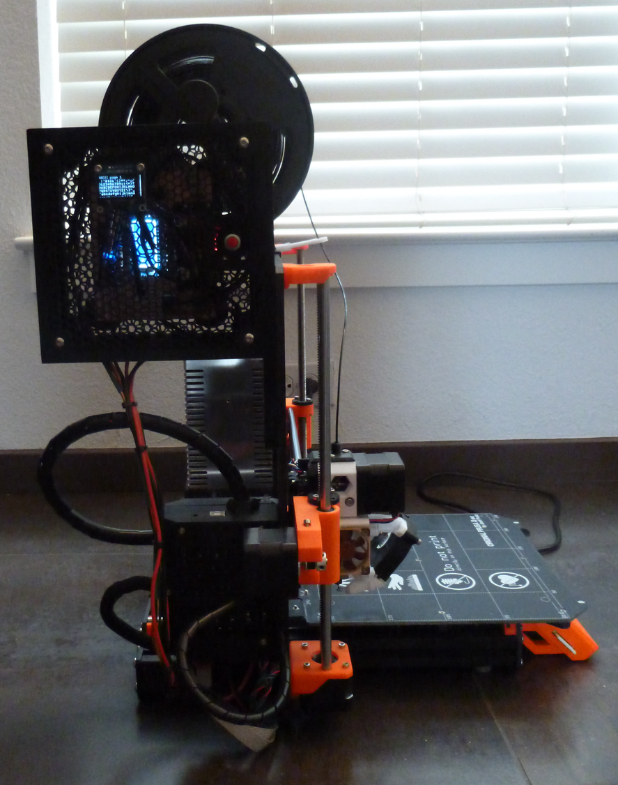
This added the OLED display and a red reset button.
Re: Quieting the R3 blower design
I'm really impressed by all the work to quiet blower.
Here are a couple of useful references for pwm control of DC fans (and issues reading the tach).
Low side pwm is easy because the transistor can be controlled without a level shifter (the fet gate is referenced to the source terminal)
But, as it's been pointed out here, the tach output is then modulated buy the PWM as well.
Seems like the super nifty solution would be to find a 4 wire fan and add a little circuit with one of the fan driver chips.
Alternately, there may be a chip that interfaces with a 3 wire fan and reports back clean tach signals.
I have not looked through the board schematic to see exactly how the einsy deals with the tach signal.
It's possible that there's a chip out there that "just" does what's needed, but a quick check at digikey turned up more results than are easy to sort.
http://www.analog.com/en/analog-dialogue/articles/how-to-control-fan-speed.html
https://www.maximintegrated.com/en/app-notes/index.mvp/id/1784
Re: Quieting the R3 blower design
Last night I tried to find on AliExpress a small board that does just this, but without luck.
Now im playing with a Raspberry Zero and the pigpio library ( http://abyz.me.uk/rpi/pigpio/python.html ) to get a decent pwm signal reading (PWM Monitor). Once you have this, the library can also be used to generate a pwm signal (Wave PWM 2). This then can be run on your pi that runs OctoPi already. I'd prefer a separate small board solution though.
By the way. once your hear this pwm noise, nothing blocks it. You indeed hear it through the whole house. It's driving me NUTS 😉 Wheeeeeeeeee
Re: Quieting the R3 blower design
I collected data on the RPM that corresponds to each duty cycle level. Then, I plotted it:
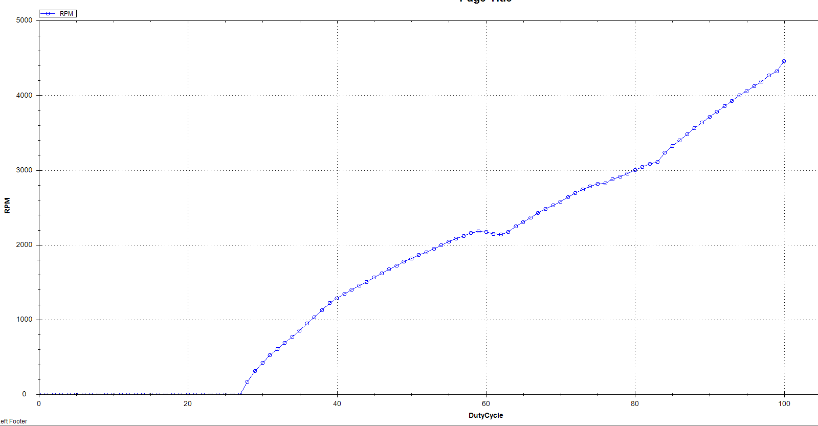
Is there a good way to make it linear?
Frequency is 7kHz.
Here's the raw data:
DutyCycle,RPM

100,4460

99,4322

98,4265

97,4187

96,4126

95,4053

94,3997

93,3924

92,3858

91,3783

90,3709

89,3635

88,3561

87,3479

86,3399

85,3323

84,3235

83,3109

82,3084

81,3043

80,2999

79,2952

78,2914

77,2877

76,2824

75,2814

74,2785

73,2739

72,2690

71,2638

70,2576

69,2528

68,2478

67,2425

66,2363

65,2300

64,2246

63,2171

62,2141

61,2148

60,2171

59,2181

58,2159

57,2117

56,2083

55,2040

54,1992

53,1946

52,1902

51,1863

50,1818

49,1773

48,1724

47,1671

46,1616

45,1561

44,1503

43,1452

42,1402

41,1343

40,1281

39,1219

38,1129

37,1031

36,946

35,854

34,773

33,691

32,606

31,522

30,424

29,309

28,167

27,0

26,0

25,0

24,0

23,0

22,0

21,0

20,0

19,0

18,0

17,0

16,0

15,0

14,0

13,0

12,0

11,0

10,0

9,0

8,0

7,0

6,0

5,0

4,0

3,0

2,0

1,0

0,0
Re: Quieting the R3 blower design
I gathered and plotted more data over a range of different PWM frequencies:
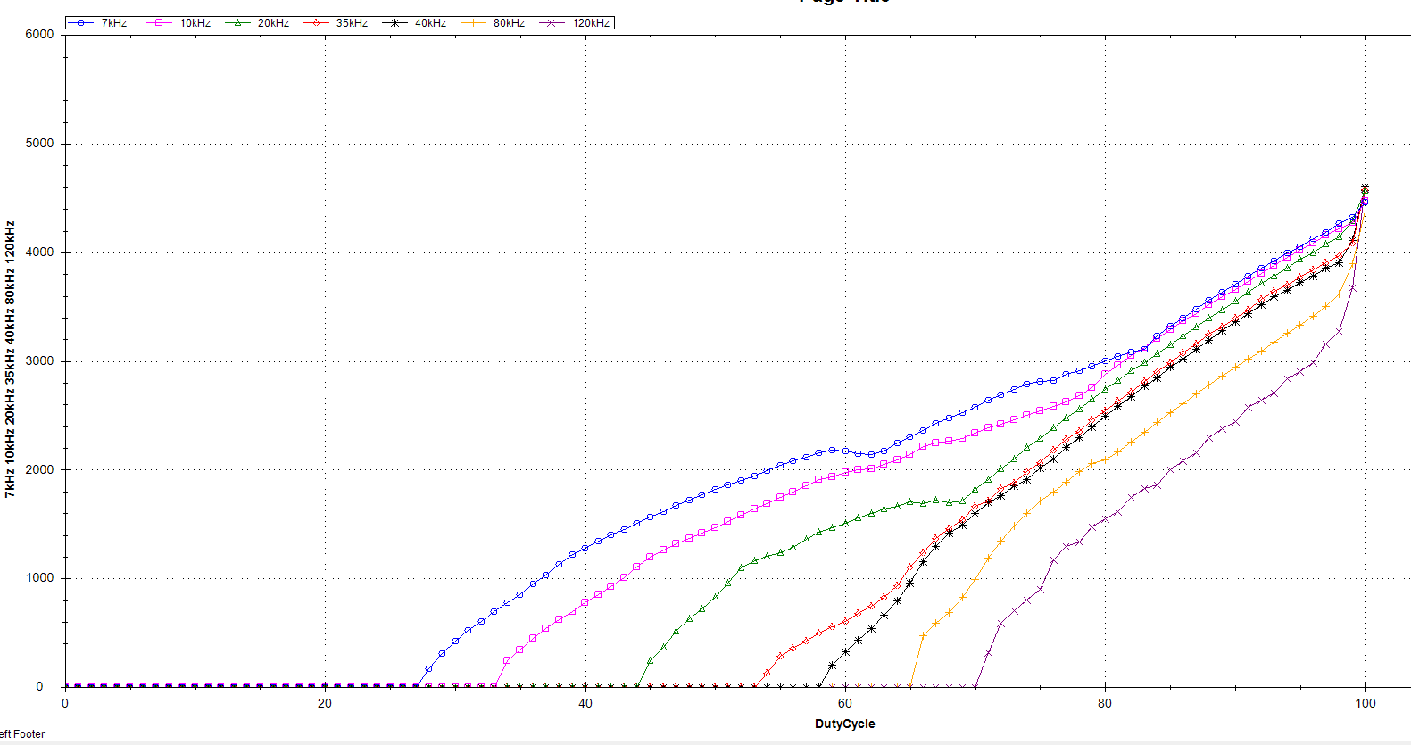
Although none of them are perfectly linear, the curves around 35kHz and 40kHz seem more linear than the others.
Re: Quieting the R3 blower design
With enough data collection and analysis, I suspect it would be possible to synthesize a true linear relationship between duty cycle and blower RPM by using a mix of PWM frequencies to compensate for the highly granular duty cycles of the hardware.
However, short of that, an easy thing to do would be to map a virtual duty cycle onto an actual duty cycle that's in a useful range. In this way, the duty cycle behaves in a way that is more intuitive and more in-line with what the slicer expects.
So, doing that with a 7Khz PWM frequency, the plot looks like:
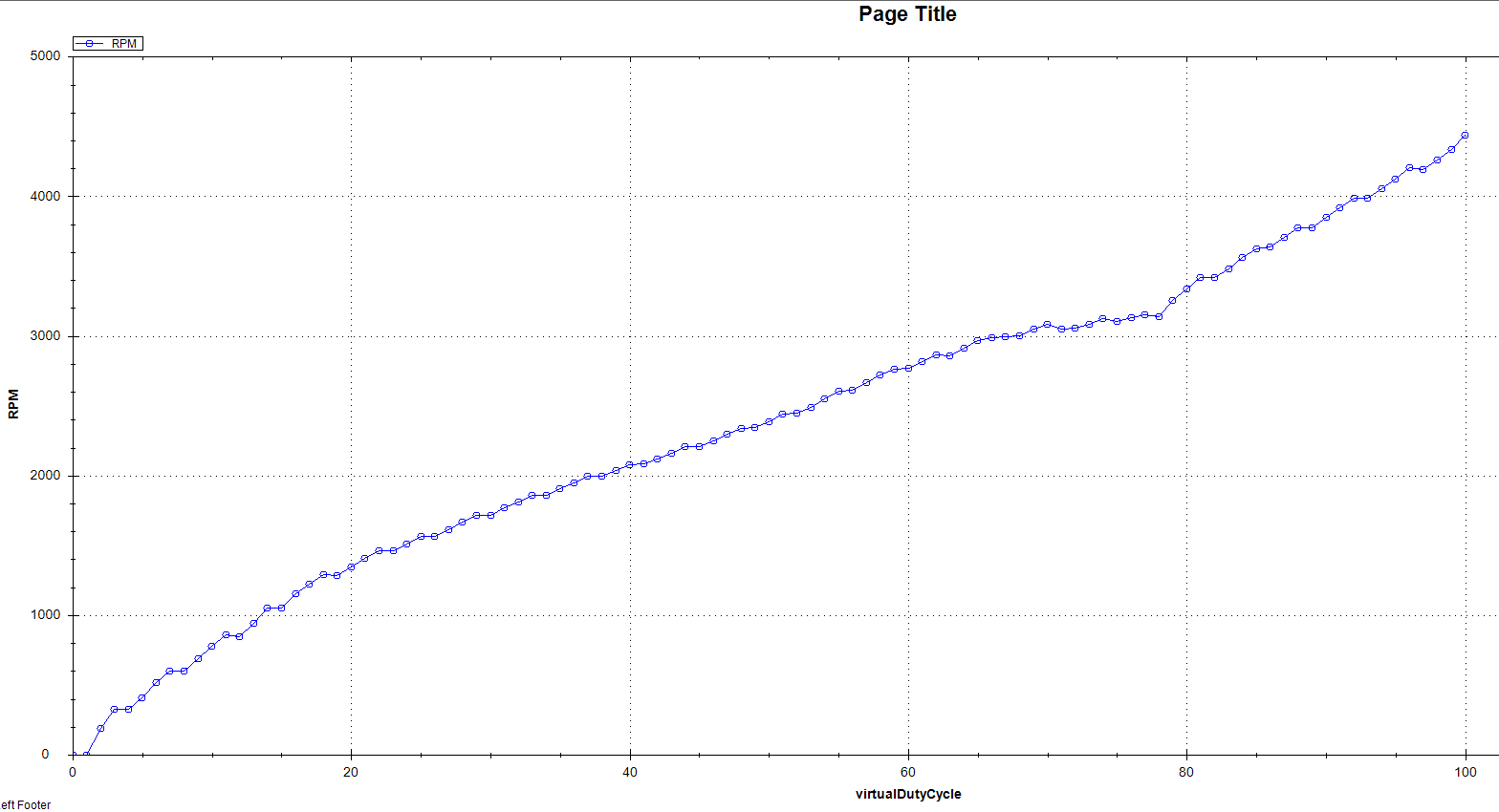
and the mapping details are:
VirtualDutyCycle,mappedActualDutyCycle,RPM

100,100,4439

99,99,4337

98,98,4262

97,97,4194

96,97,4204

95,96,4123

94,95,4055

93,94,3986

92,94,3987

91,93,3915

90,92,3851

89,91,3775

88,91,3771

87,90,3706

86,89,3636

85,89,3626

84,88,3560

83,87,3481

82,86,3416

81,86,3415

80,85,3337

79,84,3255

78,83,3138

77,83,3149

76,82,3130

75,81,3106

74,81,3124

73,80,3086

72,79,3056

71,78,3051

70,78,3084

69,77,3046

68,76,3002

67,75,2994

66,75,2988

65,74,2966

64,73,2911

63,72,2857

62,72,2863

61,71,2819

60,70,2765

59,70,2758

58,69,2717

57,68,2662

56,67,2611

55,67,2604

54,66,2546

53,65,2488

52,64,2444

51,64,2440

50,63,2387

49,62,2345

48,62,2339

47,61,2294

46,60,2248

45,59,2206

44,59,2207

43,58,2160

42,57,2119

41,56,2081

40,56,2078

39,55,2035

38,54,1992

37,54,1992

36,53,1948

35,52,1904

34,51,1856

33,51,1855

32,50,1808

31,49,1768

30,48,1712

29,48,1713

28,47,1663

27,46,1615

26,45,1563

25,45,1562

24,44,1511

23,43,1461

22,43,1464

21,42,1408

20,41,1348

19,40,1286

18,40,1291

17,39,1223

16,38,1152

15,37,1051

14,37,1050

13,36,942

12,35,845

11,35,858

10,34,777

9,33,689

8,32,598

7,32,597

6,31,514

5,30,408

4,29,325

3,29,323

2,28,188

1,27,0

0,27,0
This, then, is Version 3.
Re: Quieting the R3 blower design
My Raspberry measurements are all over the place, then again that is not so strange looking at the crappy signal shape... Pullup resistor (internal) and 4.7nF did not help 🙁
Would it not be easiest to put a resistor in front of the switching FET to limit the current (so it does not get hot) and make it switching fast by enabeling the code?
Does anybody know if the MOSFET is easy to desolder and where the thing is located?
Aside from the schematic, this is all that I've ever been able to find:

I'm afraid you'll have to sleuth out the answers you want using a multimeter and the schematic.
Re: Quieting the R3 blower design
Repeating myself: The easiest way to quiet the fan is using a much much lower PWM frequency. In Configuration.h, comment out #define FAST_PWM_FAN and comment in #define FAN_SOFT_PWM. That will take care of the noise and even helps with getting the fan started at low RPM.
Would it not be easiest to put a resistor in front of the switching FET to limit the current (so it does not get hot) and make it switching fast by enabeling the code?
No, it just makes the problem worse, no matter how you define "front". The FET becomes hot because of the switching losses, and the more sluggish the driving signal of the FET is, the worse is the problem; an additional resistor is not exactly helping in this situation. Putting an resistor at the output is just burning energy, likewise not exactly helpful.
Does anybody know if the MOSFET is easy to desolder and where the thing is located?
The Einsy board is not really tinker-friendly. No extra space, fine-pitched SMDs allover, and there is always some connector which is in the way of the solder iron. All the information regarding the PCB is on GitHub: https://github.com/ultimachine/Einsy-Rambo/tree/1.1a/board/Project%20Outputs .
Re: Quieting the R3 blower design
Here is what the OLED displays in verison 4:
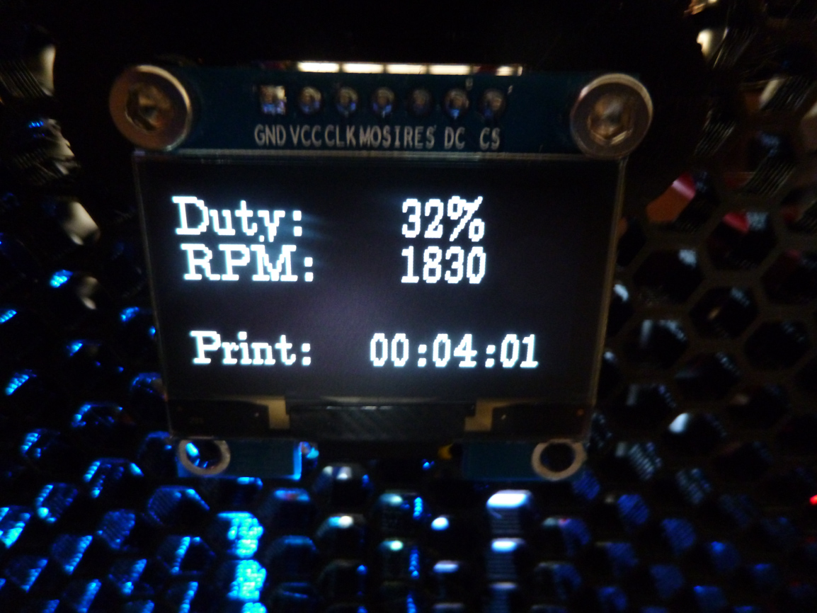
It displays the duty cycle, as measured from the Einsy, and it displays the RPM, as measured from the fan tachometer.
It also displays the cumulative time that the fan has been running. So, if you turn the fan on at the beginning of your print (even to something very small, like 200RPM), and you turn the fan off at the end of your print, then this number will show the total time required to finish your print, even if you don't come to pickup your print until hours or days after it has finished. This is information that the current Prusa firmware fails to provide, but that I want to know.
Re: Quieting the R3 blower design
Solved 😀
Thanks Dreide; today I went the easy way and compiled firmware to have in Configuration.h:
// #define FAST_PWM_FAN
#define FAN_SOFT_PWM
Great instructions are here: https://github.com/prusa3d/Prusa-Firmware on how to compile it.
My first firmware crashed as I did not edit platform.txt correctly, the 2nd firmware crashed as it was the latest development version BUT my 3rd try succeeded, based on the current stable firmware code.
Result: no more noise from the front fan!
RE: Quieting the R3 blower design
Guys keep in mind the current limitation when PWM:ing these "large" mosfets at high freqencys. The RFP30N06LE as mentioned earlier has a gate capaticance (at 5v) of 34 nC. Running mosfet at 7khz would require like 240 mA. A smaller mosfet and/or mosfet driver would be a good idea to be able to crank up the frequency properly.
RE: Quieting the R3 blower design
I have read this thread and love what you all have done. I am in process to by a delta 24v 3pin
Model: BUB0524HHB
There are no mush spec on this one. Anyway i am going to huck it up with my Mk3s+ to get better cooling.
Thanks for all knowledge you all provided here.