Re: Quieting the R3 blower design
To drive the fan correctly you need a 555 timer or a double timmer ic. Arduino is not capable of drive that as a pure fan pwm like pc motherboard does, even if you overclock the PWM at mcu you can't get near the pure 555.
In addition, it can be controlled by a microcontroller using serial commands.
Re: Quieting the R3 blower design
I revised the schematic to incorporate the lessons learned from yesterday:
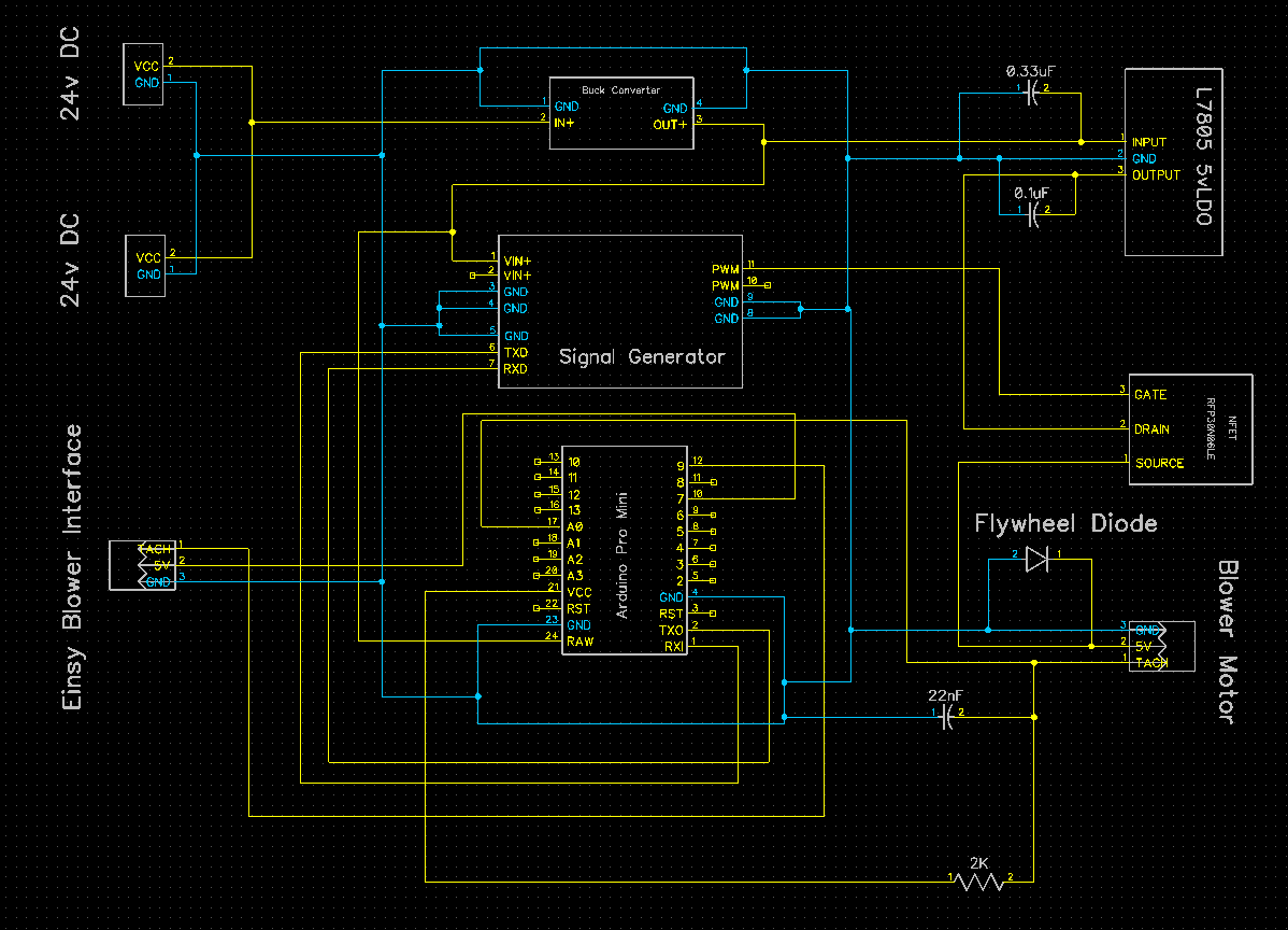
and I made it into a new PCB so that everything is current and in-sync going forward.
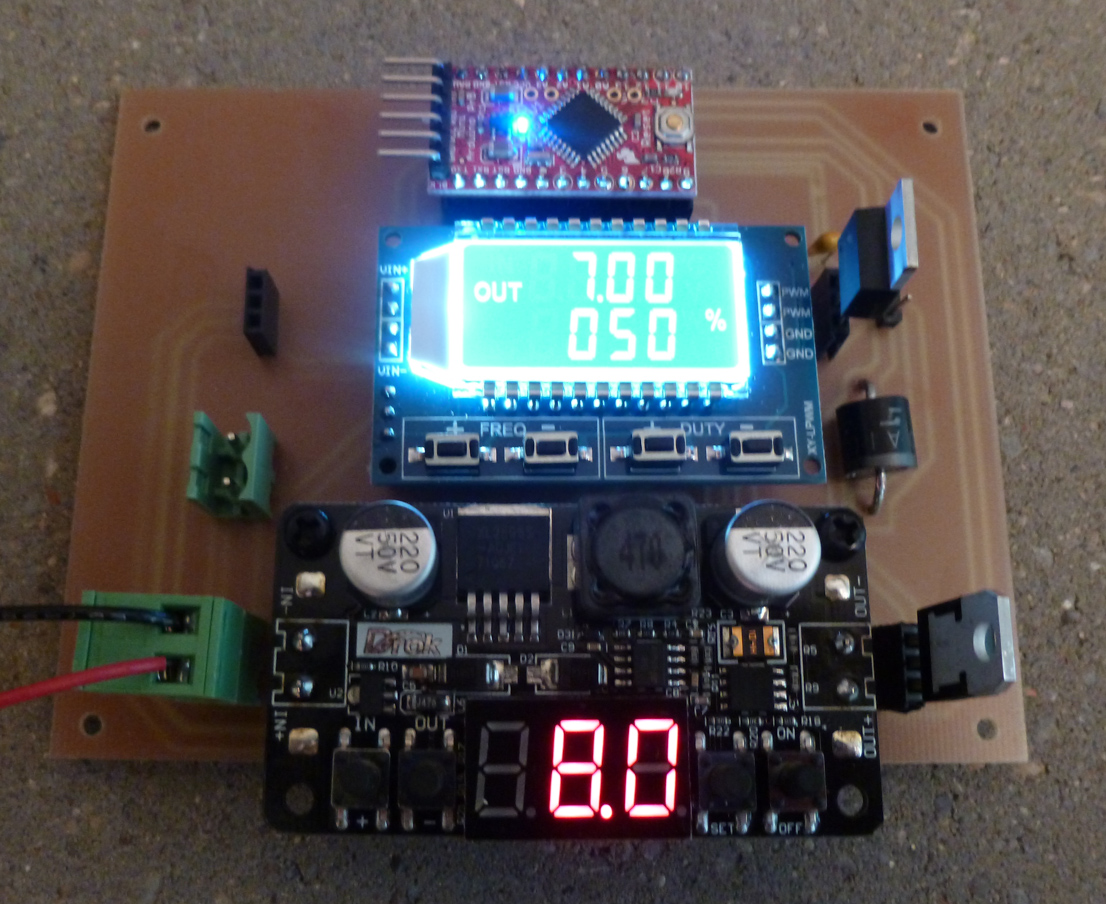
I bolted down the buck converter, because otherwise it was a bit wobbly.
Re: Quieting the R3 blower design
That's complicating and result in a huge board.
Best thing to do is build a circuit like i post into SMD.
Fan header from board connect to another fan header on new made pcb to bridge the both board and signals and then add another fan header to connect the fan on new board
ENSY FAN HEADER -- NEW PCB BRIDGE -- NEW PCB FAN HEADER
Connect jumpers to this new board then conect fan here
GND -- GND -- GND
VCC -- VCC -- VCC
TACH -- TACH -- TACH
PWM -- PWM to 555 timer -- PWM generated from 555 timer
This is the simpler and compact solution, you can toss it inside the enclosure and wire it easy.
This way you are using the arduino pwm to make the 555 timer generate the new pure pwm signal to the fan
EDIT: After seeing the prusa manual i notice fans are 3 pins, so they are controling fan with a transinstor instead of direct pwm the fan. that way on my design suggestion the PWM from 555 goes to a transistor G and the D goes to fan GND or VCC depending where the switching is been made originaly. You need a fast switching transistor or fet to take advantage of this
Re: Quieting the R3 blower design
This is the simpler and compact solution, you can toss it inside the enclosure and wire it easy.
Do you mean that you can make something small enough to fit inside the existing Einsy enclosure? That would be great. Certainly mine will be too bulky for that.
Will you be making one?
Re: Quieting the R3 blower design
I can design one for you if you want with the size of +/-2.5cm^2 for smd, or even handmade THT will be something like that anyway. For myself i will not use the mod because the noise is not significative for me. I also use a enclosure for the printer which damp alot the printer. I barely can hear anything: https://shop.prusa3d.com/forum/user-mods-octoprint-enclosures-nozzles--f65/my-handmade-enclosure-for-prusa-t23384.html
Well, there will be the added bonus of RPM control, so it's not entirely just about having it be quiet, even if that was the initial motivation.
I'd say don't do it for me--I estimate I'm more than halfway done anyway--but if you want to do it as a giveback to the community in general so that others may use it, then by all means.
Re: Quieting the R3 blower design
Well, there will be the added bonus of RPM control, so it's not entirely just about having it be quiet, even if that was the initial motivation.
I'd say don't do it for me--I estimate I'm more than halfway done anyway--but if you want to do it as a giveback to the community in general so that others may use it, then by all means.
I can draw you the schemantic and you test.
I just need to know a few things:
terminal order is VCC GND TACH?
VCC is 5V?
They are switching VCC or GND to drive the pwm?
No, terminal order is GND VCC TACH
Yes, VCC to the fan is 5v. However, I'm not sure you can rely on getting 5v from the Einsy, which is why I'm not relying on the Einsy as a power source. Instead, I'm buck converting from the source 24v voltage down to 8v (to drive the gate on the NFET via the signal generator), but I use an LDO to convert the 8v to 5v for driving the fan itself. Since the Arduino Pro Mini has its own private 5v LDO, I'm powering it with 8v. All this may be overkill, but with this approach there's no risk of inadvertently frying your Einsy, so I figure it's worth it.
I've always assumed that Prusa is switching VCC on the high side, but I've never actually checked. At least that's how I'm doing it now after earlier feedback on this thread that switching on the low side isn't good practice.
I can't promise cart blanche in advance to testing what you come up with, but hopefully someone reading this will take it on if they get inspired by your work. One development path is enough for me.
Re: Quieting the R3 blower design
No, terminal order is GND VCC TACH
Thank you
Yes, VCC to the fan is 5v. However, I'm not sure you can rely on getting 5v from the Einsy, which is why I'm not relying on the Einsy as a power source. Instead, I'm buck converting from the source 24v voltage down to 8v (to drive the gate on the NFET via the signal generator), but I use an LDO to convert the 8v to 5v for driving the fan itself. Since the Arduino Pro Mini has its own private 5v LDO, I'm powering it with 8v. All this may be overkill, but with this approach there's no risk of inadvertently frying your Einsy, so I figure it's worth it.
Have you monitor the 5V rail on einsy? If is clean without spikes or noise then is safe to use, 555 timer consumes uA.
I also against use regulated 5V from MCU to feed motors but since is low consuption is OK. They should used 24v blower instead and regulate from there.
I've always assumed that Prusa is switching VCC on the high side, but I've never actually checked. At least that's how I'm doing it now after earlier feedback on this thread that switching on the low side isn't good practice.
Maybe they are but need to be sure
Re: Quieting the R3 blower design
Have you monitor the 5V rail on einsy?
I haven't investigated it at all. I simply made some very pessimistic assumptions so that I wouldn't have any dependencies.
Re: Quieting the R3 blower design
I haven't been able to get the RPM info back to the Prusa. If I combine the Prusa TACHO input with my TACHO input, then I no longer get an accurate RPM reading, and I don't feel like revisiting that. Then I tried duplicating the signal on the Prusa TACHO every time I sample the blower TACHO with:
analogWrite(A2,((sample/1023)*255));
but that has no effect. I also tried sending it a digital signal instead, but that doesn't work either. I suppose it's expect an "open collector" signal and not the TTL or analog signal that I'm sending it.
Sooo.... I'm going to disable fan monitoring on the Prusa, and maybe I'll tack on an LED display to show RPM's continually in real time independent of the Prusa LCD interface. I'm not sure that I really need it, but it might be nice to have visual confirmation that all is well.
Anyhow, I have to press on, because I need to be done with this in a week or less.
Here are the instructions for setting the signal generator over the serial line:
Display Instructions:
There are 3 display range:
1:XXXX->the unit is 1Hz, range is 1Hz-999Hz
2.XX.X->the unit is 0.1KHz,range is 10.0KHz-99.9KHz
3.X.XX->the unit is 0.01KHz, range is 1KHz-9.99KHz
e.g.:100->100Hz;54.1->54.1KHz;1.2.4.->12KHz
Serial Control:
Baud Rage: 9600pbs; Date Bit:8; Stop Bit:1;Stop bit:1;Check Bit:none;Flow control:none
1. Set the PWM frequency:
"F101" set the frequency as 101Hz(001-999);
"F1.05":set the frequency as 1.05KHz(1.00-9.99);
"F10.5" set the frequency as10.5KHz(10.0-99.9);
"F1.0.5" set frequency as105KHz(1.0.0-1.5.0)
Set PWM'duty cycle:
"DXXX": set duty cycle as XXX;(001-100)
Read setting:
send "read" to read the set parameter. when set successfully, it will reply:DOWN;if failed, it will reply:FALL
I may have to setup separate RX and TX lines for it ("software serial" on a Pro Mini) , because it appears that if it's exposed to any text other than what it's expecting, it seems to become befuddled and no longer communicate.
[Edit: I've since tried Software Serial, and it works much better! 🙂 ]
Re: Quieting the R3 blower design
It works! I'm getting consistent measurements of both the blower duty cycle posted by the Prusa I3 MK3 and the measured RPM's on the fan:
0 -----------------------------------
Frequency=491Hz
Duty cycle=66%
RPM=2610
1 -----------------------------------
Frequency=491Hz
Duty cycle=65%
RPM=2580
2 -----------------------------------
Frequency=491Hz
Duty cycle=65%
RPM=2610
3 -----------------------------------
Frequency=491Hz
Duty cycle=65%
RPM=2580
4 -----------------------------------
Frequency=491Hz
Duty cycle=66%
RPM=2580
5 -----------------------------------
Frequency=491Hz
Duty cycle=66%
RPM=2610
6 -----------------------------------
Frequency=491Hz
Duty cycle=66%
RPM=2580
So, the hardware is now validated. I just need to etch the final revision of the PCB and then mount it in a box.
Thank you everyone for all your help. 🙂
Re: Quieting the R3 blower design
I found that you can boost PWM signal at einsy to work at +/-1KHz
You just need to hack the firmware: https://www.arduino.cc/en/Tutorial/SecretsOfArduinoPWM
Re: Quieting the R3 blower design
I found that you can boost PWM signal at einsy to work at +/-1KHz
You just need to hack the firmware: https://www.arduino.cc/en/Tutorial/SecretsOfArduinoPWM
Yes, but there's not much point to it: It won't make a difference as far as blower noise goes. It would just change the pitch of the irritating whine.
Re: Quieting the R3 blower design
Pity it can't be boosted to 30k. Then it would only any cats and dogs.
Regards,
Martin
Martin Wolfe
Re: Quieting the R3 blower design
As far as the fan noise goes, the trick is to use a lower PWM frequency. I am currently using a whopping 8Hz - yes, eight cycles per second! Just uncomment the FAN_SOFT_PWM line in Configuration.h (EDIT: and comment the FAST_PWM_FAN line, obviously). Sure, I can hear the 8Hz clicking, but this is by far less annoying than the high frequency squeaking.
EDIT: Oh, I guess this might be interfering with RPM monitoring. I can't tell, because I'm using standard Marlin without the fancy stuff.
Re: Quieting the R3 blower design
Where would be the best place to mount a project box for this on the Prusa I3 Mk3? I had been thinking it would go above the Einsy, but looking at it now I see that doing that would interfere with the movement of the printhead wiring harness. The reason I had thought it would work was this:
https://www.thingiverse.com/thing:1325370
but now I notice that he also somehow changed where the Prusa wiring hrness enters the Einsy. Not sure how viable that will be, but at the moment it seems like the best option available?
[Edit: aha! He was using a mini-rambo case for the MK2.
https://www.thingiverse.com/thing:1784538
Not sure that will work for an MK3. ]
Re: Quieting the R3 blower design
The project box will probably look similar to this:
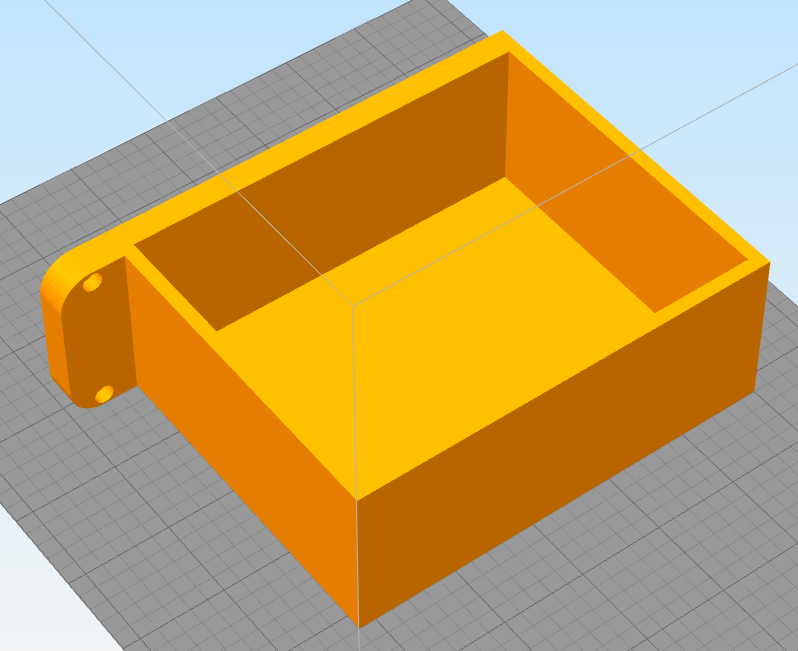
and be mounted on the Prusa I3 MK3 frame above the Einsy box.
I need to add some standoffs for the PCB and cover screws, and I'd like to add ventillation holes and maybe round the corners.
[Edit: also, it occurs to me that I can use the fan activation time and deactivation time to measure the total print time, which is a feature presently missing from the Prusa firmware. Thus, I thnk I probably will add an OLED display to the cover to show useful information like that. So, I guess I'll need two "covers": one to hold the OLED display and the other to act like a bezzel over it. ]
Re: Quieting the R3 blower design
Here is the final schematic, which includes both an OLED display and a reset button.
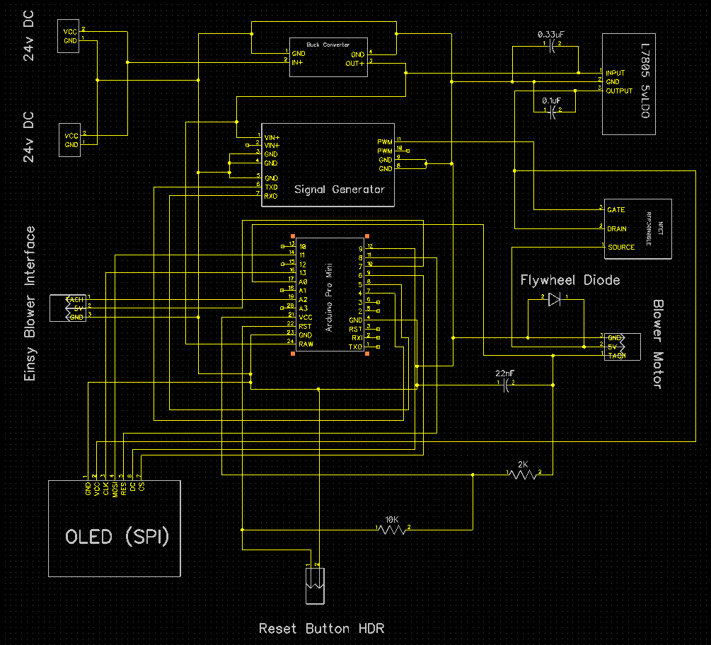
I chose an OLED with an SPI interface because those update noticeably faster than those with just an I2C interface. I also added a header for a case mounted reset button. I don't know that I'll ever need to use the a reset button, but easier to add it now than to spin a new board later if it turns out I do. Both the OLED display and reset button will be mounted on the project enclosure and connected to the PCB via JST-XH headers. I'll also be using JST-XH headers for connecting the PCB to the blower motor and the Einsy blower motor interface.
[Edit: What finally sold me on adding the OLED display was realizing I could use it to display the total print time at the end of a print job, which is something the current Prusa firmware won't do (and who knows if it ever will). ]
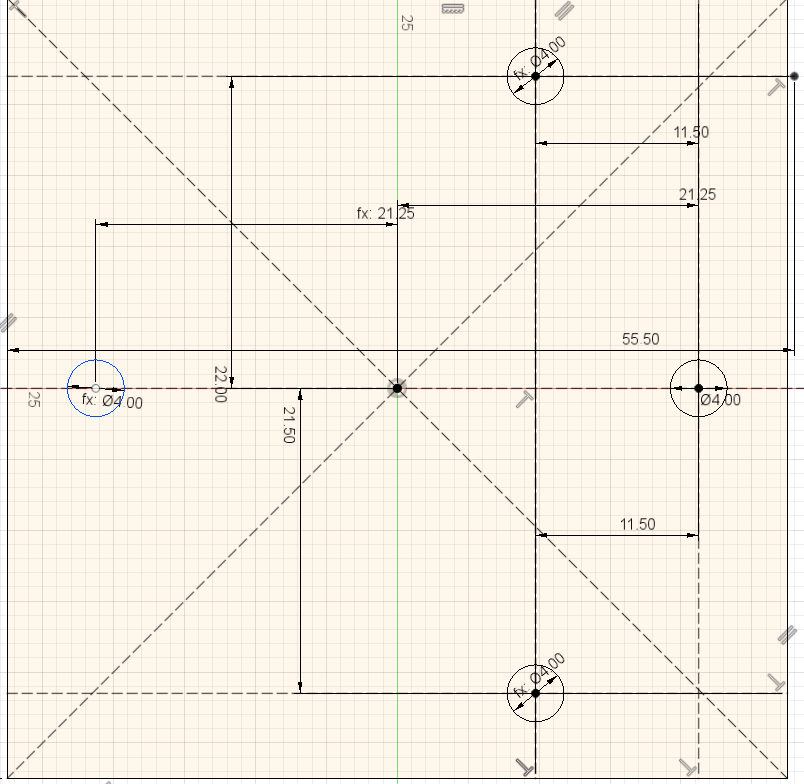
I'll be mounting the project box to all 4 of the available holes on the MK3 frame above the Einsy. I ferreted out their positions through trial and error. For reference, their relative positions are:
Re: Quieting the R3 blower design
I finished the project box for it, and I'm printing it now:
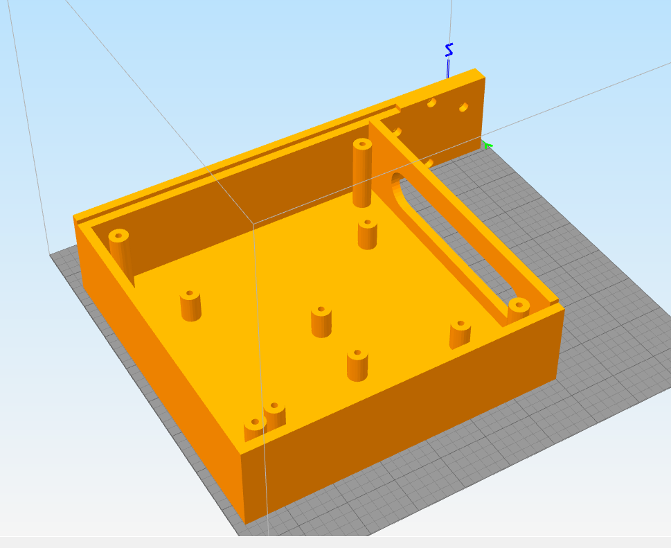
I'm fairly sure it's much bigger than it needs to be, but better too big than too small. The main challenge was putting every stand-off and hole exactly where it needs to be.
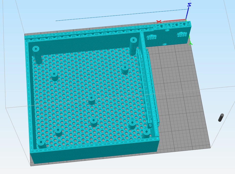
I'll try printing it in honeycomb to give it extra ventillation:
Since these monologs aren't much fun, I think this will be my last posting.
I think if/when more people start to use the R3 printed parts, more people will be running their fans at lower speeds--which makes the PWM whining more audible--and maybe then there will be more interest in this topic. I know that my reason for buying the Prusa was for its alleged quietness (= high WAF), and now it finally can be.