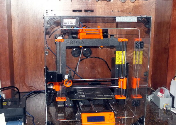
Product report. 3d Upfitters MK3S/MMU2S acrylic enclosure.
This is a review and report on the 3d Upfitters Prusa Acrylic Enclosure Kit, specifically the MMU2S model.
I do a fair amount of ABS printing, and lately even some PC Blend, and I've found that an overall improvement in print quality results from using the 'draft shield' option available in some slicers. I wanted to improve upon that and eliminate the extra time and extra filament used when using the draft shield, so I considered an enclosure.
I considered two types, one a homebrew enclosure, made of stock panels and hardware, and a 'kit' version complete with most everything.
I settled on the 3d Upfitters model after reading online reviews and posting one query here. The specific version I ordered is on line here:
https://www.3dupfitters.com/products/prusa-acrylic-enclosure-kit
I found that when all items were considered, particularly the cost of the time involved, the kit is of the same order of magnitude, price-wise, as a homebrew enclosure.
I specifically like this version because it has a portal to supply room air directly to the I3 power supply, thus eliminating the need to perform major surgery and move the power supply to the outside of the enclosure.
Much of this report contains some details of my own temperature monitor and fan controller, which I decided upon in lieu of the optional temperature monitor only option, at extra cost, which is available. I want to control the temperature of the enclosure within one degree or so if possible. The 3d Upfitters site explained that some use the enclosure for better prints and some use it for better air quality. I intend to kind of use it for both, mainly for print quality, but also so I can keep the temperature in the home office in the low 70s (F) as opposed to the high 70s that I have been using since I got the 3d printer.
Another extra-cost option which I declined was the knurled metal knob for the door. The stock one is perfectly fine for me.
The shipment was prompt, only a few days via UPS Ground, at a reasonable cost.
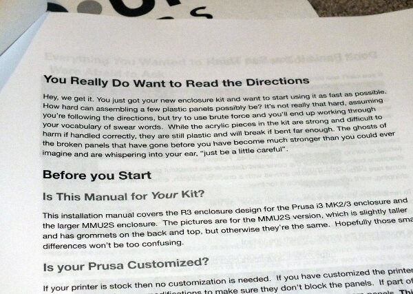
The first step was to inspect and inventory the contents of the box, which was complete and undamaged. Included was a hardcopy of TFM. Nope, no Haribo bears included in this one. 😉
The pieces are professionally cut and drilled. Ready to assemble. No 'real work' involved. 😉 All pieces are clearly marked.
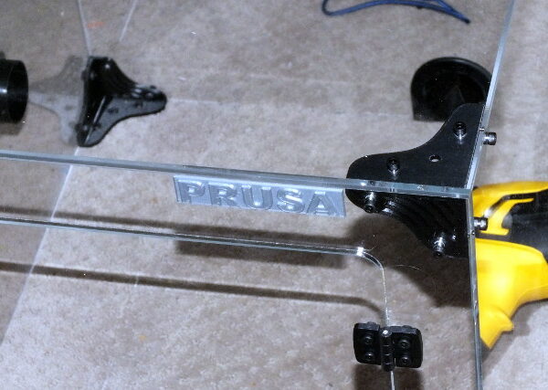
The spare bedroom floor was used as the assembly area. I also use it to assemble the larger 3d prints I do. Yes, I know that the rug could use a good cleaning, but this room is not on the 'inspection tour' of our home. 😉
When assembling a kit, I always RTFM, front to back, sometimes more than once. I must say that with this kit, TFM is really not necessary, as the assembly is quite intuitive and it only goes together one way. I did, however, follow along, step by step, with the manual.
The one thing TFM emphasized is the importance of removing the protective sheets from the acrylic panels by placing the panel on a flat surface and pulling the sheet off slowly and diagonally to avoid damage from mechanical stress. I followed this admonition carefully, and quite a bit of the clock time of the actual assembly was taken up by the removal of the protective sheets from the pieces.
There are corner brackets, side brackets, door hardware, and various items such as plastic grommets for the cables and PTFE tubes. There are far more nuts and bolts than necessary included.
I decided to first assemble the enclosure with all bolts finger tight, thus allowing the final tightening when the enclosure is in the final position and dimensionally stable.
I really don't think it's important to show the step-by-step parts of the assembly, as it's so easy. Total clock time from inventory to mostly-complete enclosure was about two hours, including adequate breaks.
A very nice plastic spool holder is included (some assembly reqired) and can be placed on top and the filament passed through the wide slot (look closely) to the printer.
This next section has to do with the temperature monitor and fan controller, and if you're not interested in this part, you can feel free to skip to the in-place installation below.
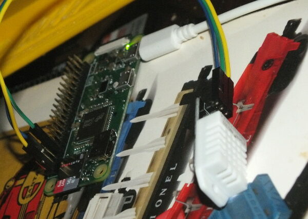
I decided to use a Raspberry Pi Zero and an off-the-shelf temperature/humidity sensor for the monitor. I really don't need humidity readings, but the sensor I had on hand included it so I might as well use it. I also keep at least one virgin Pi Zero on hand for when I need it for a project.
First was a test of the Pi and the sensor together, using the test script supplied with the sensor, to be sure that the readings were properly received by the Pi and looked sane. Notice that the temperature increased slightly and the humidity increased significantly when I breathed directly into the sensor.
Next step was tack-soldering the sensor wires to the back of the Pi board as the display will take up the entire front side of the connector.
The display I decided to use is the Inky pHat (pronounced 'inky pee-hat') which I've used on other projects. This is a 'digital ink' paper white display which is illuminated by room light as opposed to a backlight, similar to some stand-alone readers. These are available at most any maker shop. It mounts as a 'hat' to the Pi Zero directly on the main bus connector.
A quick sanity check showed that the Inky was indeed alive and well and communicating with the Pi.
The first version of the program (actually a simple python script) properly displayed the date/time and the temperature/humidity after some futzing around with font size and positioning. (I later decided to include high and low temperature set points on the display as well.)
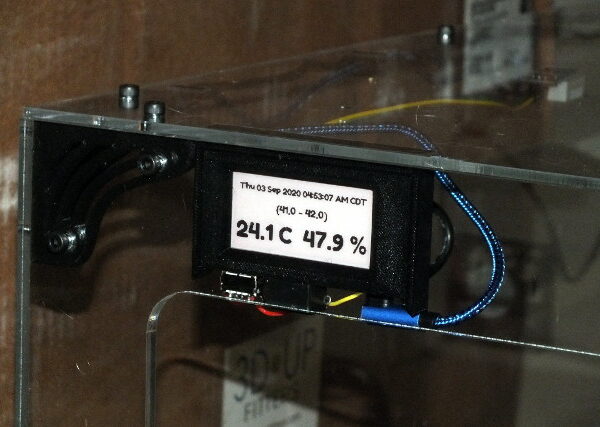
A couple of years ago I made a 3d printed case for the Pi and Inky combo for another project and I decided to repurpose that for the case for this project. I decided to only use the front, as the rear of the Pi and the wiring are not obvious when viewed from the front of the enclosure.
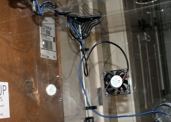
I mounted a generic USB female connector to the bottom of the case for the included (from 3d Upfitters) enclosure fan.
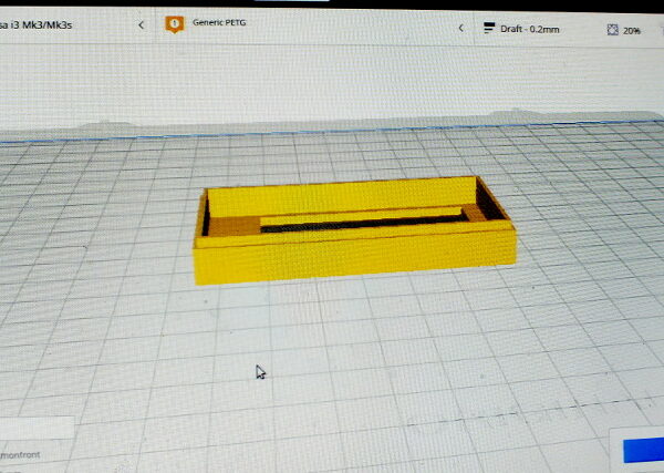
I also printed a holder for the monitor/control assembly to mount it behind the front panel on the upper left corner of the enclosure.
The sensor is mounted to the top panel of the enclosure using double-stick tape.
Wiring for the monitor power and fan is run along the sides, secured with cable clamps, and the Pi power cable passes through one of the plastic grommets to an external power brick.
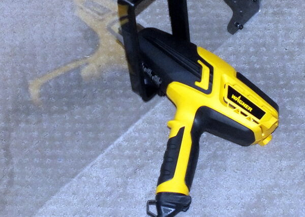
A heat gun, on the lowest setting, was used to test the operation of the sensor and fan controller, and the controller properly started and stopped the fan at the appropriate high and low control points.
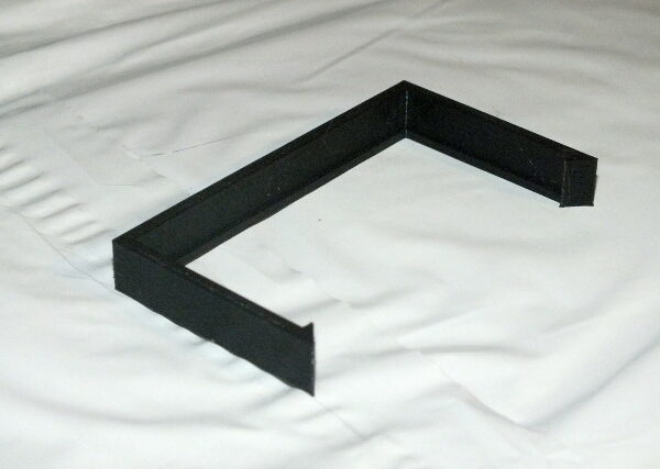
LOL, might as well make use of this particular widget, actually the first thing my MK3S ever printed, which has been lying around since February. 😉
The next big step is to install the unit in place on the counter in the home office where I have the printer.
Although I did measure before ordering, I decided to raise the shelves above the counter, along with the spool rack, for just a bit more breathing room.
I placed it in more or less its final resting place and then tightened all of the bolts, using the long end of the hex key and tightening to a comfortable tightness. I tightened on the diagonal as much as possible.
Ta-Da!
Currently I'm testing temperature. I just set it to preheat to PLA temperatures and the internal temperature is slowly creeping up. It's currently 28.7 and rising a tick every so many samples. The fan has not turned on yet.
ToDo:
Smoke detector and BFR to kill the power. At first I considered sampling a smoke detector with the Pi and using that to sound an alarm. I also considered a special smoke detector with dry contacts, but I'll most likely use an off the shelf one and sample the signal to the sounder to trigger the lockout relay to kill the power to the enclosure. Fewer failure points. I may also wire the Pi to kill the power should the temperature in the enclosure rise to some unsafe level without the smoke detector going off.
Buttons to change the temperature set points. I now have to log in to the Pi to do this. At least some presets for PLA, ABS, PETg, PCB, etc.
Improvise something to hold the enclosure in place on the counter, as in soon. The surface of the counter is too smooth to hold it in place.
Modify the program to do a minimum fan run every so often to keep air flowing across the power supply.
RE: Product report. 3d Upfitters MK3S/MMU2S acrylic enclosure.
I am considering a similar setup. Can you provide an update of your experience with the printer in the enclosure and the enclosure itself now that you have had some time with it? I have read other reports of Prusa parts sagging from heat, how is yours holding up?
RE:
I like it. Very much.
The only issues I've had are very minor and are the slight misalignment of the door, which I am too lazy to fix, which means I have to lift it very slightly to get it to fully close, which is NBD, and the tendency of my too-narrow stick-on cable clamps to fall off the inner top, which, again, I've simply been re-sticking them rather than to use larger ones or a more sticky adhesive.
No, nothing melts and sags. It does not get that warm in there. High 30s to low 40s when printing long ABS prints. I use it for PLA prints as well, low 30s. If anything, it helps with PLA print consistency.
The one item of bad news is that the way I attempted to mount things with the MMU2S (buffer vertical, behind the unit) is awkward and a pain in the @$$ to try to use. If I had more shelf space in the home office, this would be a non-issue.
When I (lately very rarely) do a MMU2S print, I just lift the enclosure off, move the printer to the floor of the spare bedroom, and do it there, using the floor space as a filament buffer, and then replace all of it when the print is finished.
Since I got the Ultimaker S5 about a year ago, when I need two colors or soluble supports I'll use that instead.
RE: Product report. 3d Upfitters MK3S/MMU2S acrylic enclosure.
Perfect! Thanks for the feedback, this puts my mind at ease. I've been researching today and I think I'm actually going to go with the Tukkari TLX. Very similar design but has a base and solid back (instead of clear acrylic). Overall price is slightly less than the 3D-upfitters version but does not come supplied with a fan, which must be supplied yourself.
RE: Product report. 3d Upfitters MK3S/MMU2S acrylic enclosure.
I just purchased one of these. I am printing the mmu2s filament holders right now on my MK#S+ and install the mmu3s update next wee.
I am looking for a temperature control for the usb fan.
I have a 110 volt controller from a computer rack But would like to keep the controller low voltage.
RE: Product report. 3d Upfitters MK3S/MMU2S acrylic enclosure.
Nice enclosure and build write up. Maybe some day I will spend the big bucks on a super cool enclosure . . . 😎


