Re: Fine Vertical Artifacts / Trinamic Chop Tuning, Any Effect?
I haven’t built my MK3 yet, but was very curious about the VFA problem in general and this thread specifically.
I was kind of shocked that the tmc2130 would have such a basic flaw – but after reading the data sheet(a lot) and running simulations of the prusa code, I think there is a bug in the tmc2130_set_wave routine. It looks to me like it is computing the delta’s incorrectly. I believe that the mslut values represent the increment necessary to go from the current output value to the next one, but the routine looks to me like it is setting the 1st mslut value based on the difference between zero and the first (i=0) value – which is always 0. It should calculate the first value of vA based on the desired 2nd output value. below is the current code, followed by what I think it should be.
code starting in Tmc2130.cpp in tmc2130_set_wave at line 874 is:
if (fac == 0) // default TMC wave

vA = (uint8_t)((amp+1) * sin((2*PI*i + PI)/1024) + 0.5) - 1;

else // corrected wave

vA = (uint8_t)(amp * pow(sin(2*PI*i/1024), fac) + 0.5);

dA = vA - va; // calculate delta
should be:
if(i<255)

{

    // use (i+1) to find delta between current(va) and next value(vA)

    if(fac1000==0) // default TMC wave

          vA = (uint8_t)((amp+1) * sin((2*PI* (i+1) + PI)/1024) + 0.5) - 1;

    else  // corrected wave

	vA = (uint8_t) ((amp * pow((float)(sin(2*PI* (i+1) /1024)), fac) ) + .5);

}

else

    vA = amp; // this is sin90 value

dA = vA - va; // calculate delta
NOTE: This works ONLY if the sin0 value is 0 (it is currently hardcoded to zero in the call to tmc2130_wr_MSLUTSTART).
If a non-zero sin0 value is desired, sin0 must be defined and the tmc2130_wr_MSLUTSTART parameters must be changed to tmc2130_wr_MSLUTSTART(axis, sin0, amp), and the 2 operative lines above should be changed to:
vA = (uint8_t)((amp+1-sin0) * sin((2*PI* (i+1) + PI)/1024) + 0.5) - 1 - sin0; // TMC method
vA = (uint8_t) (((amp-sin0) * pow((float)(sin(2*PI* (i+1) /1024)), fac) ) + .5); // "Linearity correction" method
This seems to produce correct, symmetrical zero crossings, as long as the sin0 value is 0. If one of you brave souls with a working printer, who have been working on this problem would like to try out the change, I would love to hear the results – or explanations about how I’m wrong.
Re: Fine Vertical Artifacts / Trinamic Chop Tuning, Any Effect?
Yes, you could code it that way, but as I have previously said, the zero transition glitch is smaller if sinStart is set to 1 rather than 0.
I am now forcing sinStart = 1, taking that also as prior va and forcing both sin and power correct waveforms to start with 1.
My code is now...
tmc2130_wr_MSLUTSTART(axis, 1, amp); // force sinStart = 1 for smoothest zero crossing

  va = 1; // also, set prior value = 1 to make initial delta = 0
for (i = 0; i < 256; i++)
{
if ((i & 0x1f) == 0)
reg = 0;
// calculate value
if (fac == 0)
vA = (uint8_t)round((amp - 1) * sin((2 * PI * i + PI)/1024) + 1); //Kuo modified sine wave table including force 1 at sin_start
// vA = (uint8_t)((amp+1) * sin((2*PI*i + PI)/1024) + 0.5) - 1; //original Prusa 3.5.1 default TMC wave
else // power modified wave
vA = (uint8_t)round(((amp - 1) * pow(sin(2 * PI * i/1024), fac)) + 1); //Kuo pow sine wave with forced 1 at sin_start
dA = vA - va; // calculate delta
va = vA;
BTW, good you chimed in. I was about to stop reporting new results as the topic scrolled off into obscurity.
Stepper Current Waveforms
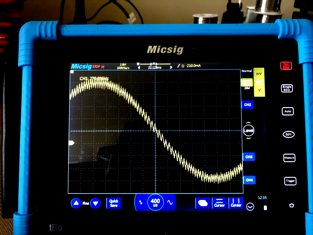
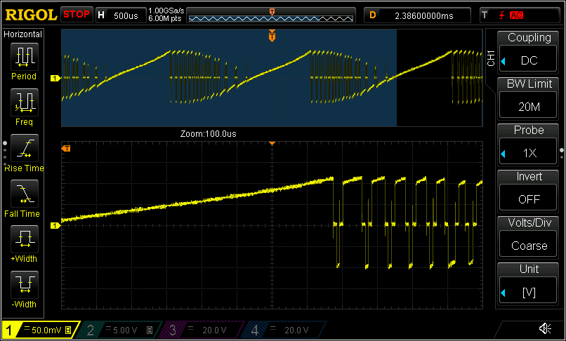
I finally got a chance to look at my stepper current waveforms with a current clamp and digital storage scope. The current probe is not lab quality, but definitely gets us the info I'm interested in seeing. I'm afraid a storage scope is required to capture the waveform because clean capture was only practical in single shot, stored waveforms.
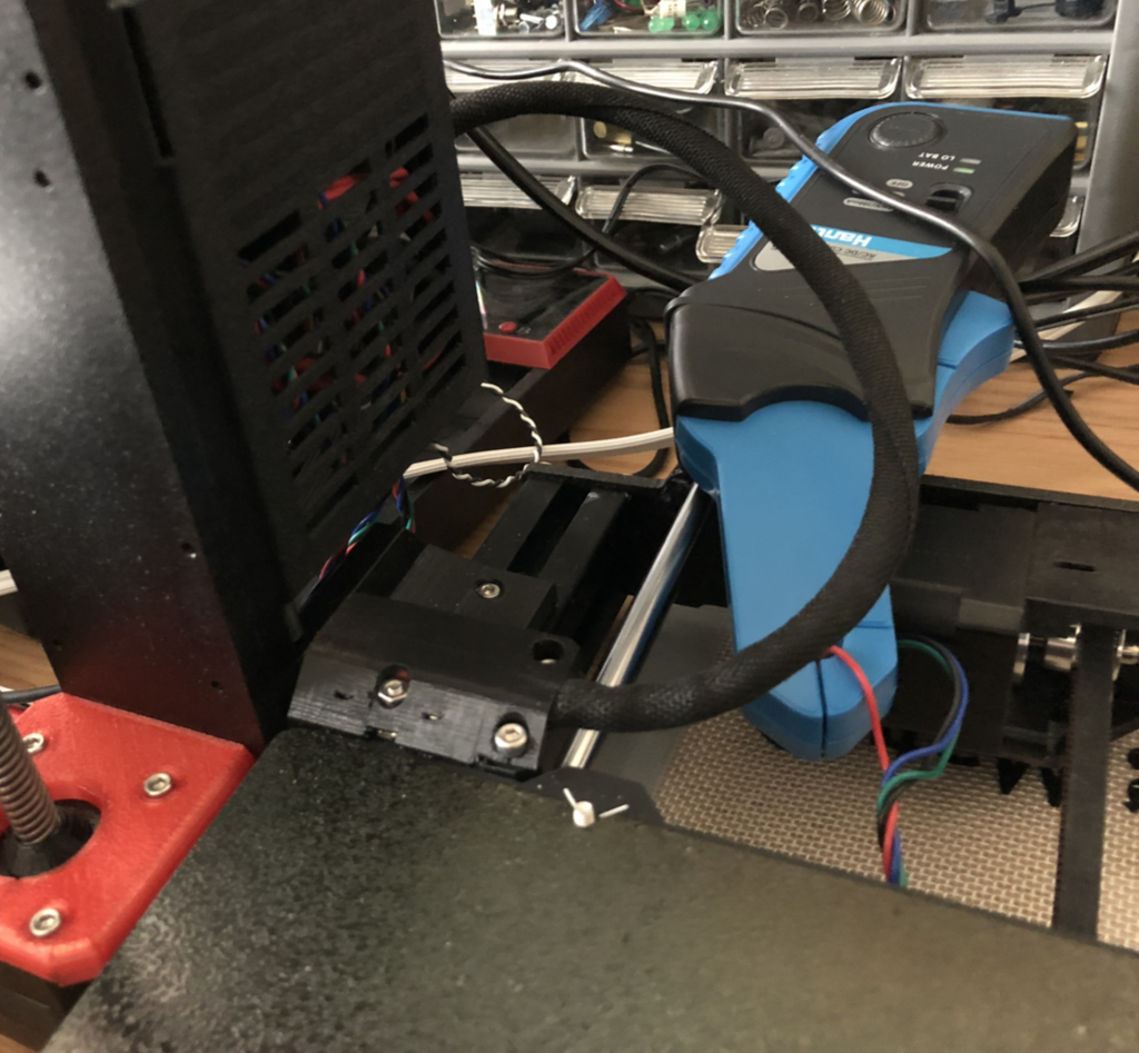
Current probe was clamped on motor wire to obtain signal. I tested on both x and y axis and obtained similar findings on both axes.
Motor current waveform was captured in single shot mode. It often took a few tries of moving the steppers to get clean waveforms. Capture at 2 msec time frame and then expanded to view zero transitions in detail.
Yes, toff, hstr, and hend affect current waveform.
hstr and hend act as a bias current across the zero crossing for Trinamic drivers. TI uses a similar offset scheme to smooth out the transition. Basically, having hysteresis current above zero causes specified current to never actually drop to zero - reducing zero crossing discontinuity. The waveform table and current setting together specify what the desired current is at each step. Chopper then converts that to pulse modulation to approximate the desired current.
For our trinamic drivers, hstr and hend specify the hysteresis current and change the shape and size of the waveform that happens around "zero crossing"
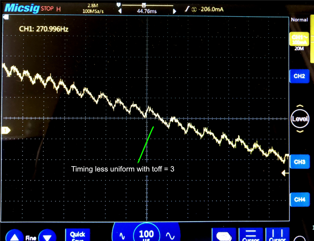
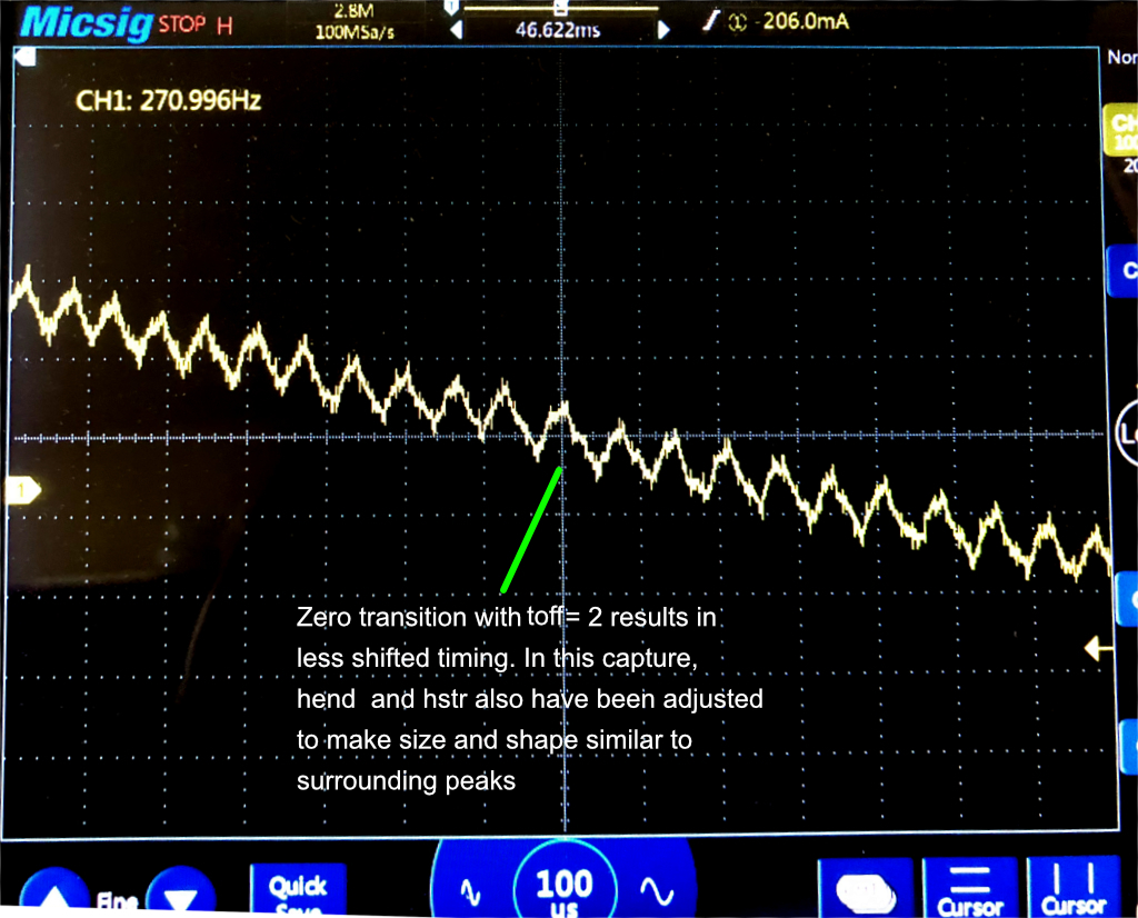
Interestingly, toff has a bigger effect than I expected. It is set to 3 in the Prusa firmware, but I found better pulse timing with toff = 2, especially in my y-axis. For my x-axis, the effect was not as definite. This also seems to be dependent on stepping speed. I have not fully characterized how speed changes whether toff = 2 vs toff = 3 is better.
Here is the zero crossing with toff = 3. You will notice that the crossover pulse seems out of phase with surrounding peaks.
With toff set to 2 and hstr/hend adjusted to shape the pulse, I could achieve a much more uniform current pulse sequence.
My best looking zero crossings were with....
y-axis
toff 2
hstr 8
hend 5
x-axis
toff 2
hstr 7
hend 6
Best values may vary with the particular steppers in each printer, but you really can't measure without a current probe and digital storage scope.
One way to do that is to hard code in firmware.
In tmc2130.cpp change
tmc2130_chopper_config_t tmc2130_chopper_config[4] = {

  {TMC2130_TOFF_XYZ, 5, 1, 2, 0},

  {TMC2130_TOFF_XYZ, 5, 1, 2, 0},

  {TMC2130_TOFF_XYZ, 5, 1, 2, 0},

  {TMC2130_TOFF_E, 5, 1, 2, 0}

};
becomes....
tmc2130_chopper_config_t tmc2130_chopper_config[4] = {

  {2, 7, 6, 2, 0},

  {2, 8, 5, 2, 0},

  {TMC2130_TOFF_XYZ, 5, 1, 2, 0},

  {TMC2130_TOFF_E, 5, 1, 2, 0}

};
or one could set the values using my experimental firmware G-codes. I think there is also a SET_CHOP_ code in the Prusa 3.5.1 firmware, but I haven't worked out its syntax.
Next, is testing how much the smoother zero transition affects prints, but that must await until after a couple 24 hour print jobs.
Firmware defaulted to toff = 2 and my best hstr, hend
Here is my custom firmware with default toff = 2.
hstr & hend also defaulted to the the values I found best by scope.
Also removed experimental M923 code for "glitching" the sine wave table. That proved too prone to missing steps in stealth mode.
Unzip to obtain hex firmware file. Printer will indicate Bunny Science mk3 if this firmware is running.
Re: Fine Vertical Artifacts / Trinamic Chop Tuning, Any Effect?
Sorry, my point was that both the Prusa code and your code are starting the mslut entries with the wrong deltas. The 1st entry should represent the difference between the sin0 value and the second desired "sin output value". The present code is calculating the 1st mslut entry based on the difference between the sin0 value and the first desired sin output value. This causes the entire regenerated sin to be shifted, and is why the zero crossings are asymmetrical. With my changes, the zero crossings are -1, 0, 1 and 1, 0, -1.
Also, the work that you have put into this issue is fantastic. I'm sure the whole community will benefit.
Thanks
Re: Fine Vertical Artifacts / Trinamic Chop Tuning, Any Effect?
Hmmn. Trinamic documentation is unclear (perhaps even misleading) as to how things are implemented.
If one takes the Trinamic spec sheet alluding to an expanded microstep table literally, then how I have been treating the zero transitions is true. One cannot ever achieve a -1, 0 , 1 transition. The reconstructed table could at best do a -1, 1 transition after symmetrical replication of the quarter wave.
If there is no actual expanded microstep table, but instead every value is being calculated on the fly from the stored delta's, then one could specify sinStart = 0 and the first delta be a 1.
We don't know which internal implementation is real. As I think about the advantages of each implementation...
Actual microstep table: lookup for any arbitrary step is a simple indexed lookup, but requires storing 1024 actual values - more silicon
vs
No actual microstep table: every lookup is dynamically calculated by stepping one at a time through the deltas and calculating the desired value. Requires stepping through the deltas n-times, but does reduces storage requirement. Less silicon, but more microcode.
-------------------
The only clue Trinamics gives is sinStart and sinStar90 are absolute initialization values that are reused. These are stated as being used each time MSCNT passes zero. If sinStart and sinStar90 and were used to reconstruct a full microstep table, they would only be needed ONCE at initial wave table reconstruction.
There is no spoon ---- uh... no microstep table and values are actually reconstructed on the fly?
If that is so, then your approach to building the first makes sense and would allow a -1, 0, 1 zero crossing.
Definitely worth testing.
Here is my firmware modified to sinStart at 0 and do the deltas with (i + 1) as you suggest.
toff, hstr, and hend are also changed back to Prusa default values (3, 5, 1)
Re: Fine Vertical Artifacts / Trinamic Chop Tuning, Any Effect?
Here is something for you guys to chew on. With the driver's default MSLUT, I stepped through one electrical cycle with the highest microstep resolution and read back the reconstructed values from the driver after each step (MSCURACT register). Zero crossings are ..., -4, -2, -1, 0, 1, 3, 4, 6, ... and ...,, 6, 4, 3, 1, 0, -1, -2, -4, -5, ...
At a given LUT position, the value is the same no matter of the stepping direction (true also with other START_SIN values) - good, one thing less to take into consideration.
I also verified that the default values for MSLUT, MSLUTSEL, MSLUTSTART are as documented in the datasheet (p.79). Note that these registers are write-only, so I had to program them with the documented values in order to be sure they resulted in the same reconstructed wave values.
I also did read back the wave values with START_SIN0/90=2/245. This actually shifts the waves [EDIT: along the current axis, i.e. up/down, not along the step/phase axis].
BTW, what is the "-1" doing in the sin-formula provided in the datasheet (p. 32) and also used by Prusa? This doesn't make too much sense to me.
Re: Yes, toff, hstr, and hend affect current waveform.
hstr and hend act as a bias current across the zero crossing for Trinamic drivers.
Eh, wait. So you are not using SpreadCycle but constant off-time chopper?
Your signals look really clean. I think I also need such a probe.
I measured directly at the sense resistor (the key is to connect to the oscilloscope input directly, without any probe, and having a termination resistor of some 50 Ohm at the input - keeps the noise down). Measuring at the sense resistor allows to see better the different phases during the switching cycles.
Since I am not running Prusa firmware, I am not 100% sure that the driver was set up in exactly the same way as it would have been with Prusa firmware, but I tried my best. This is SpreadCycle, obviously.
Re: Fine Vertical Artifacts / Trinamic Chop Tuning, Any Effect?
Zero crossings are ..., -4, -2, -1, 0, 1, 3, 4, 6, ... and .
That is a great tidbit! I think it is good evidence that indeed there isn't an actual 1024 entry table, but rather the value are being reconstructed on the fly. One less thing to worry about indeed. I simply must trial the firmware with the (i + 1) based deltas once my print job completes.
I think the -1 you are referring to is part of their roundabout avoidance of the round function.
Personally, I think it just makes the code harder to read. My code reads more easily....
// TMC2130 wave compression algorithm

.........
tmc2130_wr_MSLUTSTART(axis, 0, amp); // force sinStart = 0
va = 0; // also, set prior value = 0 to make initial prior = 0
for (i = 0; i < 256; i++)
{
if ((i & 0x1f) == 0)
reg = 0;
// calculate value
if (fac == 0)
vA = (uint8_t)round(amp * sin((2 * PI * (i + 1) + PI)/1024)); //Kuo modified sine wave table including bhawkeye delta using (i + 1)
// vA = (uint8_t)((amp+1) * sin((2*PI*i + PI)/1024) + 0.5) - 1; //original Prusa 3.5.1 default TMC wave
else // power modified wave
vA = (uint8_t)round((amp * pow(sin(2 * PI * (i + 1)/1024), fac))); //Kuo pow sine wave including bhawkeye delta using (i + 1)
dA = vA - va; // calculate delta
va = vA;
b = -1;
if (dA == d0) b = 0; //delta == delta0 => bit=0
else if (dA == d1) b = 1; //delta == delta1 => bit=1
else
{
if (dA < d0) // delta < delta0 => switch wbit down
{
//printf("dn\n");
b = 0;
switch (dA)
{
case -1: d0 = -1; d1 = 0; w[s+1] = 0; break;
case 0: d0 = 0; d1 = 1; w[s+1] = 1; break;
case 1: d0 = 1; d1 = 2; w[s+1] = 2; break;
default: b = -1; break;
}
if (b >= 0) { x[s] = i; s++; }
}
else if (dA > d1) // delta > delta0 => switch wbit up
{
//printf("up\n");
b = 1;
switch (dA)
{
case 1: d0 = 0; d1 = 1; w[s+1] = 1; break;
case 2: d0 = 1; d1 = 2; w[s+1] = 2; break;
case 3: d0 = 2; d1 = 3; w[s+1] = 3; break;
default: b = -1; break;
}
if (b >= 0) { x[s] = i; s++; }
}
}
if (b < 0) break; // delta out of range (<-1 or >3)
if (s > 3) break; // segment out of range (> 3)
//printf("%d\n", vA);
if (b == 1) reg |= 0x80000000;
if ((i & 31) == 31)
tmc2130_wr_MSLUT(axis, (uint8_t)(i >> 5), reg);
else
reg >>= 1;
// printf("%3d\t%3d\t%2d\t%2d\t%2d\t%2d %08x\n", i, vA, dA, b, w[s], s, reg);
}
tmc2130_wr_MSLUTSEL(axis, x[0], x[1], x[2], w[0], w[1], w[2], w[3]);
}
Re: Fine Vertical Artifacts / Trinamic Chop Tuning, Any Effect?
BTW, good you chimed in. I was about to stop reporting new results as the topic scrolled off into obscurity.
Please don't stop reporting. Some of us, at least me, are following with great interest though with nothing to contribute. This is effort you have undertaken one of the great benefits of open source. Some one with a real interest (and a bit of time) can chase down a real problem that may not otherwise get addressed. Recording the process and not just the results is a very important part of the process from my perspective. It lets people know that real problem solving comes in fits and starts and isn't just a "here's a problem", "think about it", "and now I found the solution on the first go".
My time for such investigations is heavily limited due to other requirements on my time at my current stage in life, so I am living vicariously through others. So please, carry on reporting. If nothing else, I'll chime in with a bit of encouragement from time to time. 😉
Re: Fine Vertical Artifacts / Trinamic Chop Tuning, Any Effect?
I concur!!! Even though I don't understand much the science behind this, I do understand the broad strokes and can see the value. Been following your thread since its beginning. I suspect implementation of these drivers has been right off the data sheet and no one has really looked at this in great detail. Well done, sir!
Re: Fine Vertical Artifacts / Trinamic Chop Tuning, Any Effect?
Thanks for the support. We'll keep plugging away. It definitely isn't a straight forward process. Even my original concept of how the step table is internally implemented appears to be incorrect.
With the feedback of the last two days, I think we're closer to figuring this problem out.
Re: Fine Vertical Artifacts / Trinamic Chop Tuning, Any Effect?
I think I've figured out how to reconstruct the complete wave from the MSLUT. Here is the recipe:
1. Translate the zeros and ones in MSLUT to the respective deltas based on the information in the MSLUTSEL register and as described in the TMC2130 datasheet.
2. Construct the list of deltas for the full cycle, the MSLUT360 so to speak, like this: A,B,C,D, -D,-D,-C,-B, -A,-B,-C,-D, D,D,C,B.
For the sake of simplicity, I assumed a very short MSLUT of just 4 bits length, i.e. representing 4 microsteps, where A,B,C,D refer to the 4 signed deltas. The whole cycle in this toy example consists of just 16 microsteps. where the first 'A' corresponds to MSCNT=0, and the last 'B' to MSCNT=15 (corresponding to MSCNT=1023 for the real thing). Notice the missing 'A's and the too many 'D's in this sequence.
3. When stepping forward, first increment the microstep counter MSCNT before adding the corresponding delta, MSLUT360[MSCNT], to the CUR_A value (CUR_A = unscaled coil A current value = wave value). When stepping backward, first subtract MSLUT360[MSCNT] from CUR_A before decrementing MSCNT. For CUR_B, just use MSLUT360[MSCNT+256] instead of MSLUT360[MSCNT]. MSCNT (and MSCNT+256) is never negative and has a roll-over at 1024 (i.e. use modulo-1024 arithmetic). CUR_A and CUR_B are signed and roll over at 256 and -257 respectively, i.e. these values are NOT just clamped to the range of possible values [-256..255]. Whenever MSCNT=0, initialize (CUR_A,CUR_B) with (START_SIN,START_SIN90), without further applying any delta value at this MSCNT position.
Discussion: The 2nd and 4th segment in the MSLUT360 sequence are oddly shifted along the MSCNT axis. This is probably not a bug but a smart feature, because it helps breaking unwanted symmetries, especially near the zero-crossings (i.e., where the 'A's are). Perfect symmetry would also mean perfectly symmetric round-off errors, which would result in potentially higher velocity disturbances, beat frequencies, and what not else, especially near the zero-crossings. There is also a shift along the CUR_A/B axis, which comes from how the START_SIN values are used for curve offset initialization. Both shifts have to be taken into account when calculating the values for MSLUT. The "+PI/1024" term in the sin()-formula (datasheet, p.32) apparently compensates for the horizontal shift, whereas the "-1" term helps with the vertical shift. Even if these terms are sub-optimal (and I am not saying they are - depends on the optimization criterion anyway), at least the formula is reasonably simple and accurately reproduces the documented default values.
Phase rather than amplitude issue?
That shifting you see meshes with a thought I had this morning.....
I tested the (i + 1) delta change for the step table wave generation, but it made no improvement in the VFA's. I think there is something else going on.
We know that the VFA problem happens once every complete electrical cycle.
We also established that 256 DELTAS are stored, beginning with delta from zeroth value (sinStart).
Those deltas are used on the fly to generate the micro step wave values.
There are 1024 steps / cycle
There are 256 steps per quarter cycle
Here's what dawned on me ……
We calculated 256 deltas for the compressed quarter wave.
There are only 255 deltas between the 256 values.
If the implementation steps though the deltas going backwards and forwards, at the end of one cycle, we're 3 to 4 delta steps out of phase.
That would make an error that recurs once per full cycle.
I think we need to alter the PERIOD over which we are calculating the quarter wave deltas to compensate for an inherent phase error.
Maybe even do the 1st 3/4 of the quarter wave separately to stretch/expand the played back delta distribution into better alignment.
Much to digest and think about. Thanks for getting that detailed data.
Re: Phase rather than amplitude issue?
We calculated 256 deltas for the compressed quarter wave.
There are only 255 deltas between the 256 values.
But in the end we need 256 deltas for covering the quarter wave, no matter what.
If the implementation steps though the deltas going backwards and forwards, at the end of one cycle, we're 3 to 4 delta steps out of phase.
No. Stepping through it backwards is basically just undoing the deltas that have been applied when going forwards. Moreover, the SIN initialization is just a one time thing. Even for a completely screwed-up MSLUT, the deltas are mirrored in a way that the algorithm always ends up at the initialized SIN value when it arrives at MSCNT=0.
That would make an error that recurs once per full cycle.
I think we need to alter the PERIOD over which we are calculating the quarter wave deltas to compensate for an inherent phase error.
Maybe even do the 1st 3/4 of the quarter wave separately to stretch/expand the played back delta distribution into better alignment.
I don't think that there is anything wrong with the sine wave programming or the wave decoding in the Trinamic drivers, and I also don't think that changing the MSLUT will really help a lot in overcoming the problems that are causing the FVA in the first place (whatever they might be). Playing with the START_SIN values looked most promising, because those can have a big effect which does not repeat within the electrical cycle. Unfortunately, the START_SIN effect itself is not tweakable. What I find somewhat discouraging though is that the FVA looks different on the opposite sides of the test cube. This might be due to the different printing directions but could also be just the result of other factors (like the printing position (X), asymmetries of the nozzle, etc.).
Well, I am glad that I am not so much bothered by FVAs anyway.
Re: Fine Vertical Artifacts / Trinamic Chop Tuning, Any Effect?
@guy.k2, did the (i+1) change result in symmetrical zero crossings, that crossed at zero on your 'scope?
If so & based on your comments about changing the START_SIN values, I’ve been looking at making the fac1000 value signed.
Positive values of fac1000(all you can currently choose) always reduce the slope near the zero cross points(the higher the value, the lower the slope), so allowing negative fac1000 values will allow increasing the slope near the zero cross points – without losing symmetry or the zero value at the zero cross positions on the wave.
I’ve been working on this type of adjustment in the code. It works well in simulation, but now I’m trying to implement it in the firmware, without breaking anything (very frustrating that I don’t currently have a working MK3).
Let me know if you would like to see the changes, once they are complete. As you said, this may not even have an affect on the VFA's, but I'm considering that it might be a contributor so I'll probably keep going.
Re: Fine Vertical Artifacts / Trinamic Chop Tuning, Any Effect?
The (i+1) was only tested with one of my trinamic test tower prints that vary parameters with height (like the Prusa ecore tower)
Yes, let's see what you come up with regarding the fac1000. You really need to put your mk3 together and get test printing.
I'm still pondering the delta count vs current value count. Sure we end up using 1024 deltas in one cycle, but storing 256 deltas when only 255 should exist and then using those deltas across four quarters is really messy.
There is something happening every full electrical cycle. Nothing else can create the VFA's in such perfect phase.
Modify Period to fix phase experiment
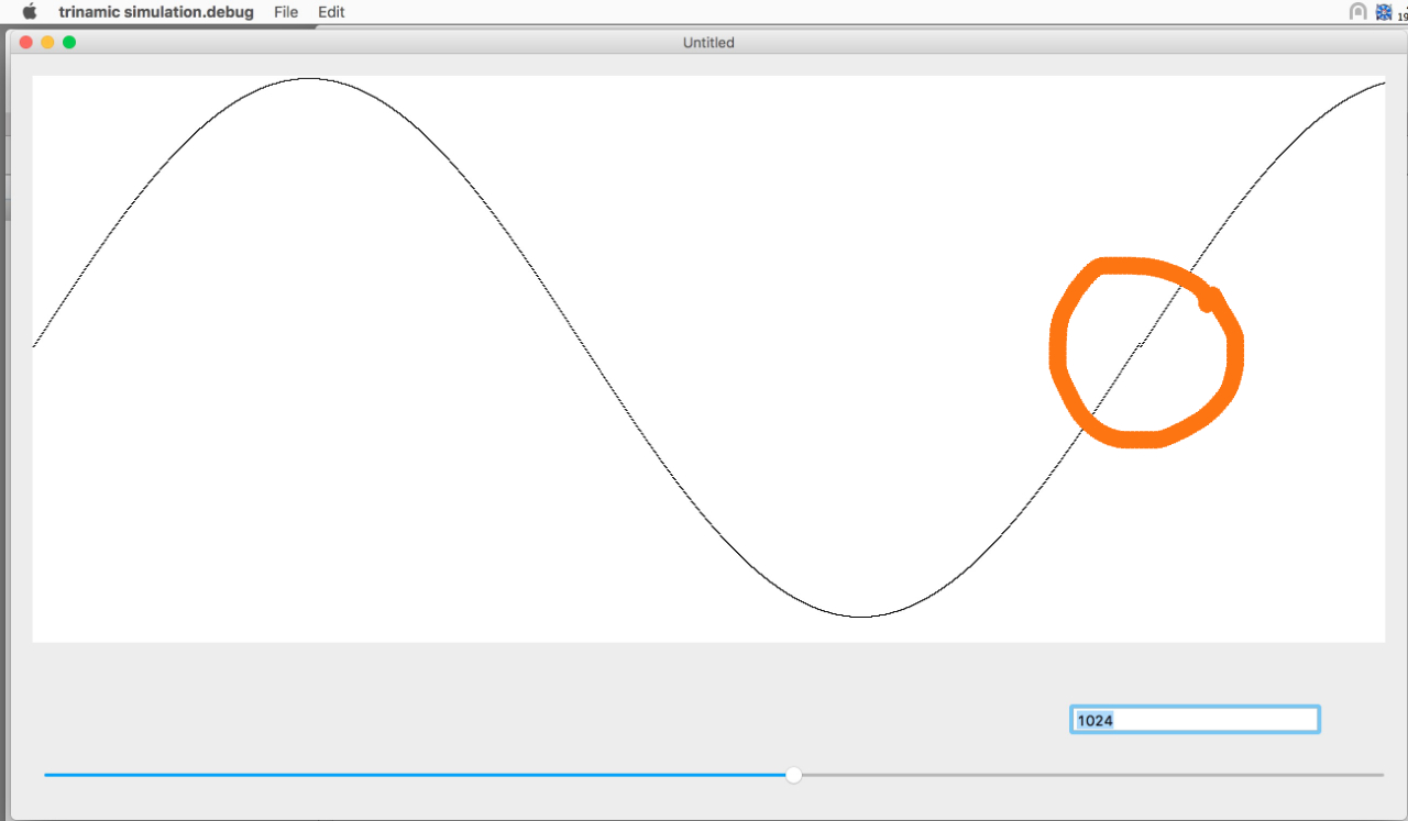
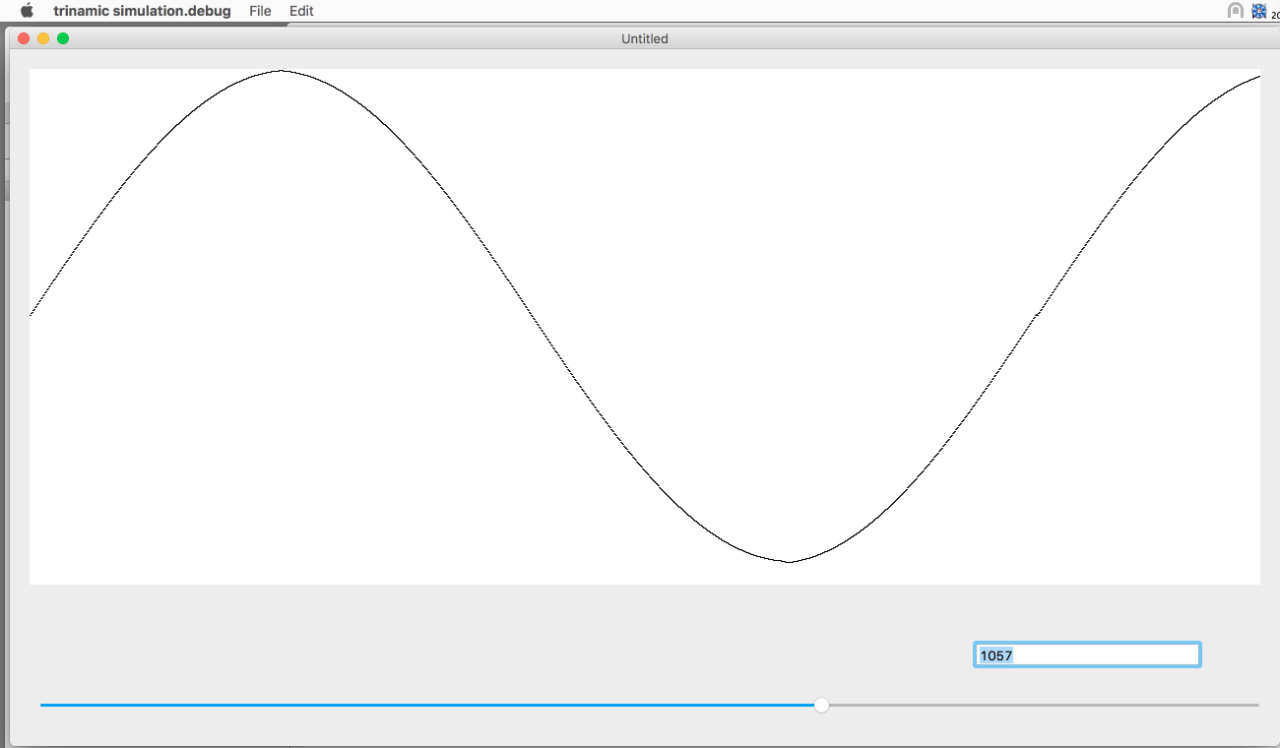
I wrote a simulation of how I would use multiple counters, limits, and directional incrementers to implement a trinamic driver's wave table system. I don't have internal knowledge of how the chip is actually built, but tried to emulate using what we do know. It was easiest (least complexity) to implement if I did nothing to compensate for the number mismatch between deltas and wave values.
The simulation demonstrates a discontinuity between each full electrical cycle. The little glitch looks a lot like what I see on multi-cycle oscilloscope captures. That glitch is fairly resistant to changing sinStart and amplitude. This matches what I see in test prints - only a minor change when sinStart is modified.
One quick thing to reduce the glitch is to alter the period over which we generate the 1/4 wave. Pedantically, that is wrong, but useful for testingmy theory that the VFA is due to a counter mismatch.
By pushing the period to about 1057, the inter-cycle glitch is reduced. The overall waveform is also reshaped, but not horribly different from a sine wave.
I have written a special version of the firmware that lets me alter the generated sine wave period using an m-code. A test tower with varying wave period commands is now printing. We'll see if this alters the VFA more than the minor changes achieved thus far.
Re: Fine Vertical Artifacts / Trinamic Chop Tuning, Any Effect?
@guy.k2, this is probably a stupid question, but have you tried a gcode of "D2130E?wave"? It disables the stepper power, then steps through every position of the table and prints the actual, reconstructed value to stdout. it then restores everything to normal & returns. (of course, the E could be X, Y, or Z)
