Fine Vertical Artifacts / Trinamic Chop Tuning, Any Effect?
WARNING: This thread contains adjustments and firmware modifications that should never be undertaken by the inexperienced. You can royally mess up your machine if you don't know what you are doing. I think vertical fine artifacts are the biggest flaw keeping my Mk3 from achieving fantastic print quality. I'm exploring Trinamic chopper tuning to if vertical fine artifacts can be eliminated. You can follow the journey. Maybe we'll get a solution.
===============
I have refined printer mechanicals about as much as possible - to the point that vertical fine artifacts are the main remaining surface flaw. I see it much more on the y-axis surfaces than x-axis, but it is present both axes. There has been previous work on Trinamic tuning to reduce these artifacts, but sadly the OP on GIThub has all but vanished after saying he was able to tune Trinamic settings to reduce fine vertical artifacts. https://github.com/prusa3d/Prusa-Firmware/pull/771
XPILA said there that experiments to auto-tune the parameters were under way. Then silence........ but the flaw is in practically every Mk3 printed object I see posted on the forum. Look carefully and you will see it. We enjoy the silence benefits of our Trinamic drivers, but we also live with its (new) flaws.
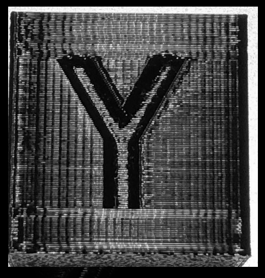
I'll refer to these artifacts as FVA's in this thread. Here is a photo that illustrates the noise. This is a black, 2 cm, PETG cube with point specular lighting angled to reflect off surface. Exposure was adjusted to emphasize surface defects.
Notice the vertical fine lines that are perfectly in phase on the y-surface? Those are the VFA's that occur on x and/or y axis depending on how well your steppers match the Trinamic drivers. Not all our steppers are identical. So, some of us see the artifact more than others. Also, this VAF's are obscured by rod and bearing alignment issues. Those smear the VFA lines horizontally. After my full Planar, Parallel, Square alignment, the smearing is gone. So I see the VFA's sharply.
I first modified firmware to change discrete parameters and after a few flash cycles, changed tactics. I ended up modifying firmware to adding some experimental Gcodes to let me set toff, hstr, hend, and tbl without re-flashing. It's a LOT easier to send Mcodes via Octoprint terminal.
======= Begin DANGER, Will Robinson
Here is what I did in the firmware.....
in Configuration_prusa.h
uncommented the below to enable TMC2130 service codes.
//#define TMC2130_SERVICE_CODES_M910_M918
in Marlin_main.cpp added to the service code case statements
case 919: //! M919 - Set TMC2130 toff

     {

     uint8_t a = 0;

     uint8_t theValue;
if (code_seen('X'))
{
a = 0;
theValue = code_value();
}
if (code_seen('Y'))
{
a = 1;
theValue = code_value();
}
if (code_seen('Z'))
{
a = 2;
theValue = code_value();
}
if (code_seen('E'))
{
a = 3;
theValue = code_value();
}
tmc2130_chopper_config[a].toff = theValue;
printf_P(_N("tmc2130_toff[%c]=%d\n"), "XYZE"[a], tmc2130_chopper_config[a].toff);
tmc2130_setup_chopper(a, tmc2130_mres[a], tmc2130_current_h[a], tmc2130_current_r[a]);
}
break;
case 920: //! M920 - Set TMC2130 hstr
{
uint8_t a = 0;
uint8_t theValue;
if (code_seen('X'))
{
a = 0;
theValue = code_value();
}
if (code_seen('Y'))
{
a = 1;
theValue = code_value();
}
if (code_seen('Z'))
{
a = 2;
theValue = code_value();
}
if (code_seen('E'))
{
a = 3;
theValue = code_value();
}
tmc2130_chopper_config[a].hstr = theValue;
printf_P(_N("tmc2130_hstr[%c]=%d\n"), "XYZE"[a], tmc2130_chopper_config[a].hstr);
tmc2130_setup_chopper(a, tmc2130_mres[a], tmc2130_current_h[a], tmc2130_current_r[a]);
}
break;
case 921: //! M921 - Set TMC2130 hend
{
uint8_t a = 0;
uint8_t theValue;
if (code_seen('X'))
{
a = 0;
theValue = code_value();
}
if (code_seen('Y'))
{
a = 1;
theValue = code_value();
}
if (code_seen('Z'))
{
a = 2;
theValue = code_value();
}
if (code_seen('E'))
{
a = 3;
theValue = code_value();
}
tmc2130_chopper_config[a].hend = theValue;
printf_P(_N("tmc2130_hend[%c]=%d\n"), "XYZE"[a], tmc2130_chopper_config[a].hend);
tmc2130_setup_chopper(a, tmc2130_mres[a], tmc2130_current_h[a], tmc2130_current_r[a]);
}
break;
case 922: //! M922 - Set TMC2130 tbl
{
uint8_t a = 0;
uint8_t theValue;
if (code_seen('X'))
{
a = 0;
theValue = code_value();
}
if (code_seen('Y'))
{
a = 1;
theValue = code_value();
}
if (code_seen('Z'))
{
a = 2;
theValue = code_value();
}
if (code_seen('E'))
{
a = 3;
theValue = code_value();
}
tmc2130_chopper_config[a].tbl = theValue;
printf_P(_N("tmc2130_tbl[%c]=%d\n"), "XYZE"[a], tmc2130_chopper_config[a].tbl);
tmc2130_setup_chopper(a, tmc2130_mres[a], tmc2130_current_h[a], tmc2130_current_r[a]);
}
break;
======= End DANGER, Will Robinson
Here is what I have learned thus far...
1. Trinamic chop tuning parameters have no effect on stealth mode.
I wasted quite a bit of time in Stealth mode trying to tune parameters, but saw zero effect.
Slaps hand on forehead.
toff, hstr, hend, and tbl only apply to standard, spread-cycle mode.
More to follow as I get results. This is going to take a while.
Re: Fine Vertical Artifacts / Trinamic Chop Tuning, Any Effect?
Finally got my test M-codes working correctly. Corrected code in 1st post. Prior attempt wasn't getting parameters due to way Marlin parser works. One MUST grab the parameter value immediately after testing for existence of the axis code. Otherwise, the parameter value gets munged.
I'm going to try some test cubes with manual tuning settings. If those display changes in the VFA's, my next goal will be an E-core type tower with a custom layer change script to automatically step through Trinamic settings as object prints.
Re: Fine Vertical Artifacts / Trinamic Chop Tuning, Any Effect?
Got some results. Tough to capture in pictures.
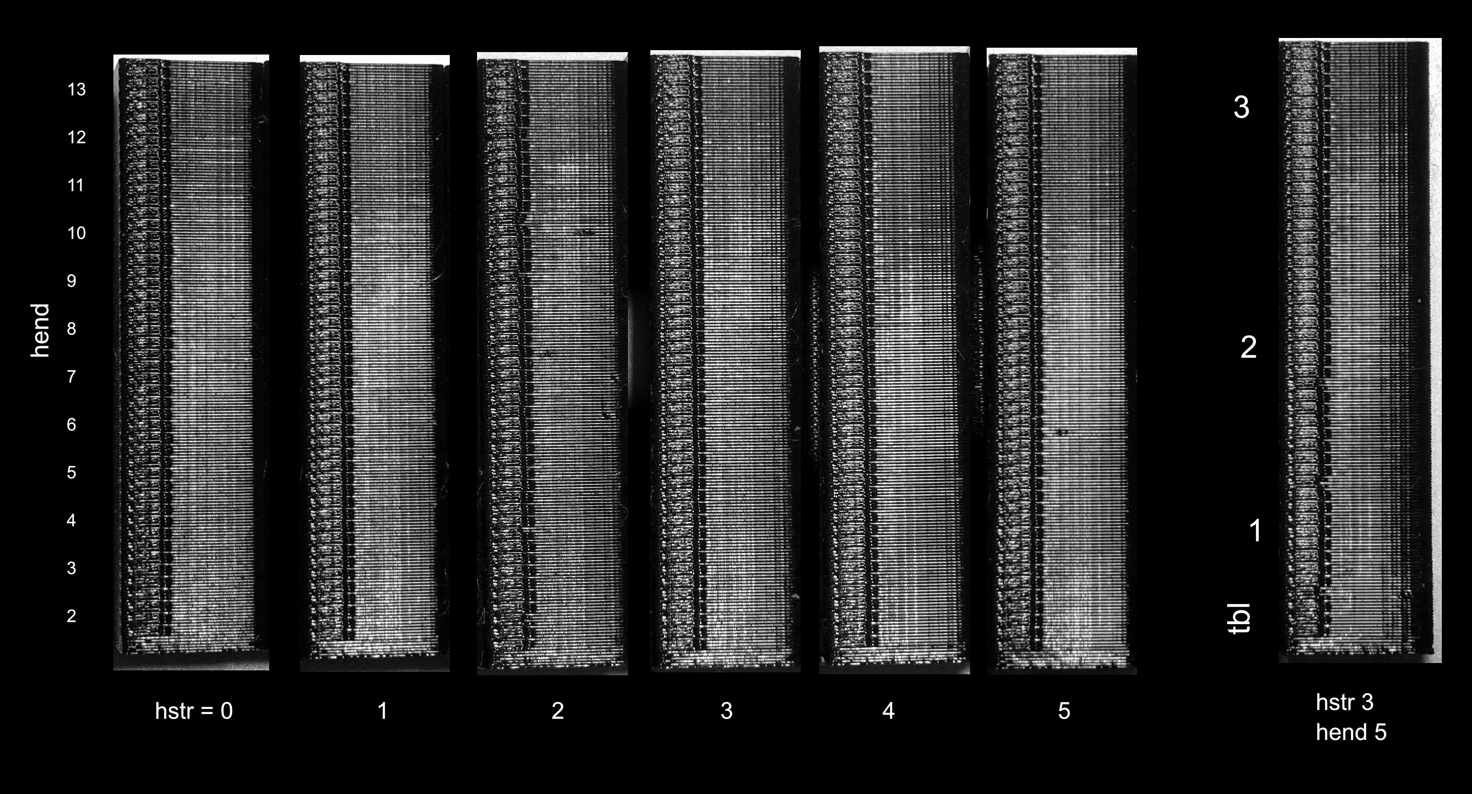
Above are six "trinamic" towers. The group of five are tests with hstr held constant as hend increased with tower height
The rightmost one is with hstr and hend at Prusa defaults and toff varied with height.
Only y-stepper was adjusted for these towers and therefore only the worst y-face shown.
Sorry about the seam. These are single thickness towers without any infill. Standard mode, of course.
Differences in VFA were VERY subtle despite audible changes in y-stepper sound. Some combinations create screaming motor resonances.
I think my y-stepper is best with hstr 2 and hend 7. It's not a huge difference, but the VFA's are milder than with stock hstr 5, hend 1.
Varying tbl didn't seem to make much difference in VFA's.
Also tested rndtf to 1 in tmc2130_setup_chopper. That randomizes toff time and definitely reduces audible stepper noise in normal mode. I had to interrupt a print job to check mode because the printer was so quiet in normal mode. I thought I had accidentally turned on stealth mode. I don't see any visible print effects from rndtf = 1. So, I'm leaving that active for now.
I think I've adequately scratched my Trinamic tuning itch. Back to happy printing....
Re: Fine Vertical Artifacts / Trinamic Chop Tuning, Any Effect?
Did you also do the E-correction calibration?
Re: Fine Vertical Artifacts / Trinamic Chop Tuning, Any Effect?
Linearity correction only tested on the extruder. Basically, on mine, the off position actually looks best. The xyz linearity corrections are active in 3.5.1, but I have not done a detailed test on those axes.
Re: Fine Vertical Artifacts / Trinamic Chop Tuning, Any Effect?
How does the XYZ cube look when printed in normal mode, now after you have tuned the spread-cycle parameters?
What I find most puzzling is that the pattern repeats with the electrical cycle (4 full-steps = 0.64mm), which cannot be easily explained by just some asymmetry in the motor coils (A vs. B, be it at a driver level, or the motor level, or somewhere in between (PCB, current sense resistor, connectors, wiring)). I conclude that also polarity of the current flowing through the coils must play a role, which speaks for some asymmetry in the driver's output stage, in addition to possibly other asymmetries.
I wonder how the pattern would look like if you swapped Y and Y (by swapping pin assignments in the firmware and swapping the plugs for the X and Y motors on the PCB).
Re: Fine Vertical Artifacts / Trinamic Chop Tuning, Any Effect?
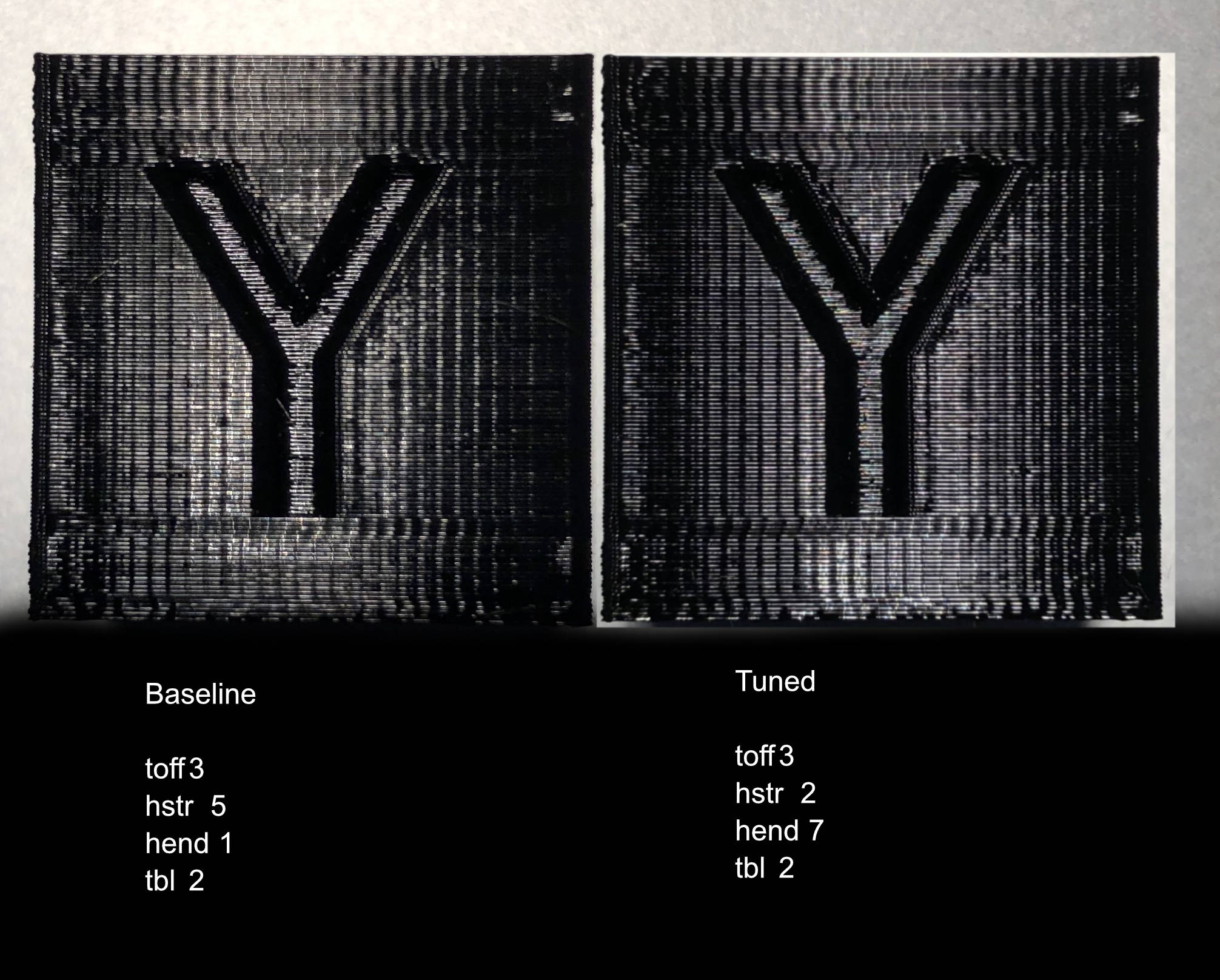
Here is pre-and post cube y-faces. Very subtlely less depth of the VFA. I can see it live, but don't have the ability to get lighting and position exactly same between photos. Unfortunately, differences created by the photo lighting completely swamp out the surface changes. Depending on lighting, the VFA depth can be made to look deeper or shallower. In the above, the tuned one photographed as being worse despite it being the opposite to my eyes.
At any rate, the change is too subtle to consider hstr and hend maladjustment the main source of the VFA's.
I agree something else related to the overall the stepper cycle is happening. Every four full steps is odd. Is there an interrupt or adjustment that happens every four steps?
Once a current probe arrives, I'll try to see what the coil waveforms look like on my scope.
I also have a Moon's stepper arriving to further my testing.
Probably will end up revisiting hstr, hend, and tbl with the scope as well.
Re: Fine Vertical Artifacts / Trinamic Chop Tuning, Any Effect?
Looking in https://www.trinamic.com/fileadmin/assets/Products/ICs_Documents/TMC220x_TMC222x_Datasheet.pdf
It is different chip but has more details documented.
The TMC22xx includes an internal microstep table with 1024 sine wave entries to generate sinusoidal motor coil currents. These 1024 entries correspond to one electrical revolution or four fullsteps
Does this sound familiar? Maybe a discontinuity in how the table is getting stepped through?
We also know that the wave table is stored as just a quarter cycle to save space. Is unpacking the wave table correctly happening?
I'm not easily reading through the unpack routine.
Re: Fine Vertical Artifacts / Trinamic Chop Tuning, Any Effect?
Now making more. The TMC2130 is where compression is being used to save space, not the EINSY EEPROM. TMC2130 only stores 1/4 of the current waveform in a compressed format. Most of
void tmc2130_set_wave(uint8_t axis, uint8_t amp, uint8_t fac1000)
is for compressing the calculated current waveform before sending it to the TMC2130.
The amplitude of the generated wave is limited to allow headroom for the tiny hysteresis current (set via hstr and hend)
That explains why hstr and hend have such a tiny effect on visible printing. They do very little compared to the bulk waveform.
standard sine wave
vA = (uint8_t)((amp+1) * sin((2*PI*i + PI)/1024) + 0.5) - 1;
Linearity correction changes the base sine waveform by raising it to a power. That steepens the sine and has a larger bulk effect.
vA = (uint8_t)(amp * pow(sin(2*PI*i/1024), fac) + 0.5);
The opposing coil is at 90 degrees and its (cos) lookup point in the table is also set by the routines.
Raising by a power isn't the only waveform alteration possible, but we're limited by needing the quarter waveform to be symmetric when replicated for all four quarters of a full cycle. Also, the steepness of curve changes is limited to what the compression can handle.
Without changing tmc2130_set_wave, our current, largest way of altering waveform shape is via linearity correction.
sine wave formula modified
[EDIT was over concerned about sine table generation code in 3.5.1. It did not match what I would write. I erroneously thought it was an oversight, but it appears to stem from formula on Trinamics data sheet. ]
In tmc2130.cpp,
void tmc2130_set_wave(uint8_t axis, uint8_t amp, uint8_t fac1000)
has the default, sine wave generated with i 0 to 255 as
vA = (uint8_t)((amp+1) * sin((2*PI*i + PI)/1024) + 0.5) - 1; //Prusa 3.5.1 sine wave table
That is NOT purely a quarter sine wave. Similar to that on the Trinamic data sheet. Both of those have some jiggering to force final table value to match amp value.
I think it is better as
vA = (uint8_t)round(amp * sin(2*PI*i/1024)); // Kuo adjusted sine wave table
The code values come out pretty close. So turns out not to be big issue.
Firmware changed to test revamped formula and machine runs fine, but really no print difference.
I'm less concerned about the difference now.
Re: Fine Vertical Artifacts / Trinamic Chop Tuning, Any Effect?
I now understand why the phase offset is added to the original formula. The 0th table entry gets duplicated and negated at zero crossing.
If the sine wave was phase aligned to make the 0th value actually be zero, the table lookup would make a larger glitch during zero crossing.
Without phase shift, zero crossing values would be 3, 0, 0, -3.
With the phase, we end up with 4, 1, -1, 4.
The 1 to -1 transition is still slightly glitchy, but not as bad as a repeated zero.
That brings me to the next problem. Current level is set to a predetermined value at the end of each full cycle. That is set to be 0 in the firmware, but because we don't have zero as the 0th table entry, drive current will blip by 1/457 at the end of each FULL cycle, but not at the mid-cycle zero transition.
i.e, with the mismatch, the inter cycle zero crossing is -4, 0, 1, 4 instead of the desired -4, -1, 1, 4
I don't know if 1/457 current error is a significant error, but it IS one that happens once per cycle, but not at mid cycle - and matches the VFA frequency.
I'm going to match the start current value to match the actual table entry value. That should remove the blip between electrical cycles.
Re: Fine Vertical Artifacts / Trinamic Chop Tuning, Any Effect?
That brings me to the next problem. Current level is set to a predetermined value at the end of each full cycle. That is set to be 0 in the firmware, but because we don't have zero as the 0th table entry, drive current will blip by 1/457 at the end of each FULL cycle, but not at the mid-cycle zero transition.
Woah, dude - good catch! I completely overlooked this detail. A blip of 1/457 might indeed not have a direct effect, but if I understand correctly, this would be not just a blip but a systematic offset of the whole curve, causing polarity-specific differences in the coil current. Moreover, the value for coil B gets initialized at cnt=0 as well, instead of initializing the coil B value with the same value as for coil A but at cnt=256. Getting the initialization value for coil B wrong (i.e., START_SIN90) causes a different "blip" for coil B, and the blip effects of both coils might add up. Also, the curve values are just the basis for further calculations before getting to the final current values. These calculation might come with round-off errors that amplify the "blip" effects. So yes, promising lead.
Even if the default programming of the current table is just fine in theory, adjusting the START_SIN0 and START_SIN90 values could still be useful for ironing out sample-specific imperfections e.g. in the driver's output stage.
Re: Fine Vertical Artifacts / Trinamic Chop Tuning, Any Effect?
Depending on how Trinamics implemented their waveform decompression, you're right. That could shift the entire wave if they do everything as deltas if they used sin_start and sin_start90 as baselines and built the wave using the compressed deltas.
I'm now testing with some mods to tmc2130_set_wave. I think I have sin_start at proper values and cleaned up the sine wave generation.
.....

	int i;                         //microstep index

	uint32_t reg = 0;              //tmc2130 register
if (fac == 0) // default TMC wave
//vA = (uint8_t)round((amp) * sin(PI/1536)); //this is actual sin_start calculated value for default TMC wave
tmc2130_wr_MSLUTSTART(axis, 1, amp); // evalutes to 1. Set 1 as sin_start value
else
// vA = (uint8_t)(amp * pow(sin(0), fac) + 0.5); // linearity modified wave
tmc2130_wr_MSLUTSTART(axis, 0, amp); // evalutes to 0. Set 0 as sin_start value
for (i = 0; i < 256; i++)
{
if ((i & 0x1f) == 0)
reg = 0;
// calculate value
if (fac == 0) // default TMC wave
vA = (uint8_t)round((amp) * sin((2*PI*i + PI)/1024 + PI/1536)); //Kuo mod sine wave table including phase shift
// vA = (uint8_t)((amp+1) * sin((2*PI*i + PI)/1024) + 0.5) - 1; //Prusa 3.5.1 sine wave table
else // corrected wave
vA = (uint8_t)(amp * pow(sin(2*PI*i/1024), fac) + 0.5);
dA = vA - va; // calculate delta
........
So far it looks a bit better, but the print changes are not day and night.
Probably have to go back and retune hysteresis for the newly fixed zero transition.
I think (but have not verified) that stealth mode is autotuned. It should already show better performance even before I can get hysteresis manually tuned. I tried a the stealth mode printout (which I believe is autotuned for zero transition) and it is more noticeably better than comparing standard mode printouts.
BTW, stealth mode definitely shows less VFA compared to standard mode. That is consistent with it auto-tuning its zero transitions better than spread-cycle's manually tuned hysteresis.
I'm approaching 100 test cubes chasing this VFA issue. Visual comparison is tough. Sometimes it is easier to compare the degree of VFA by running my fingernail across the VFA's to feel which printout is smoother.
Hopefully, the current probe will let my scope speed up the tuning with fewer test prints. Still waiting for the probe and Moons stepper to arrive.
Re: Fine Vertical Artifacts / Trinamic Chop Tuning, Any Effect?
Could you try with intentionally wrong START_SIN values (like START_SIN=5), just to see what the effect in the print out is? I am not sure though, if the amplitude of the wave (248 in the default table) would have to be changed in order to avoid saturation effects (i.e. the effective curve values plus hysteresis and whatever hitting the 255 limit).
MK3 inherent VFA's - Most likely are Trinamic driver related.
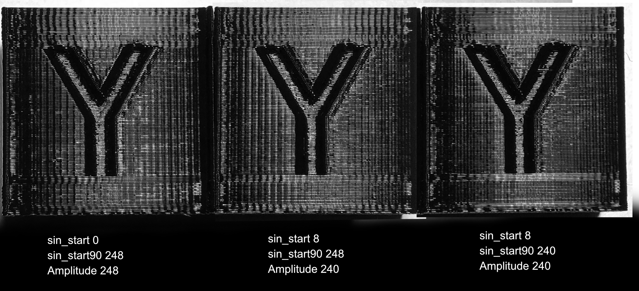
That was a great idea to intentionally use incorrect sin_start values. I made the error magnitude 8 and reduce magnitude to keep the values in range. As a second test I did this with and without matching sin_start90 to the resultant waves. We theorized that a larger error at the start of quarter wave (sin_start) will worsen existing VFA. Also, inducing an error at the end of quarter wave (sin_start90) will create a new VFA between existing VFA's.
Look at the results...
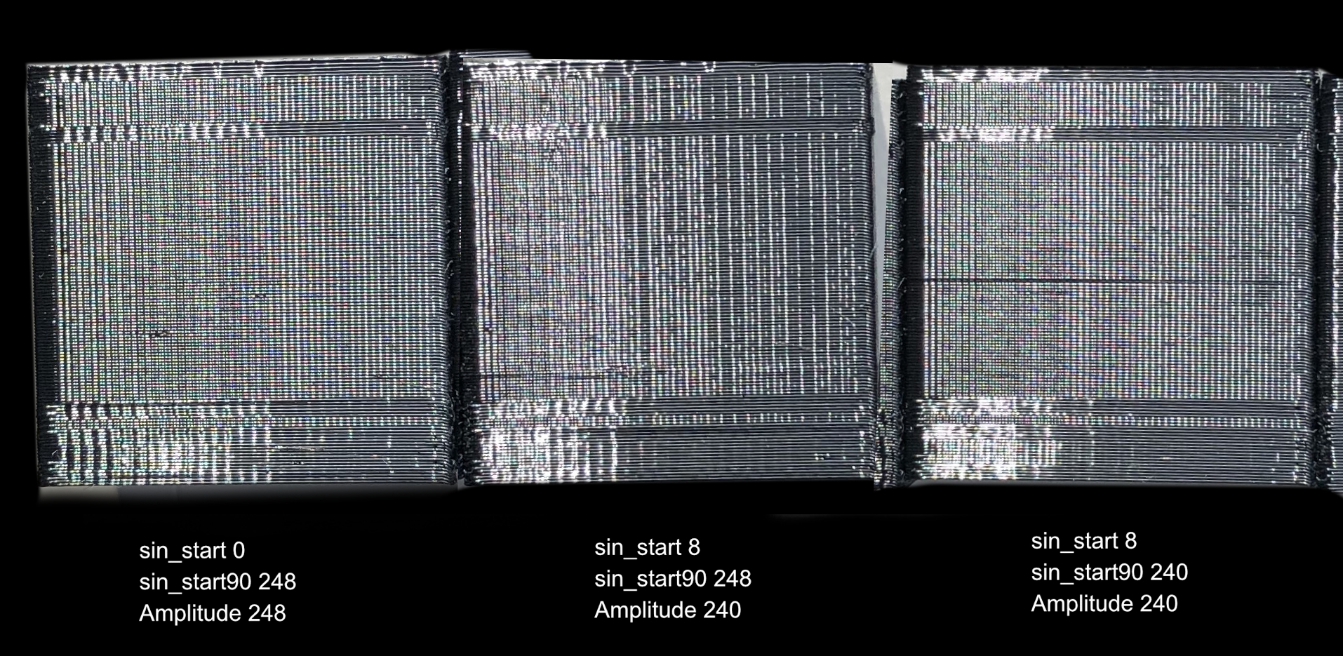
The left image is with Prusa 3.5.1 default values. Sin_start is erroneously zero instead of one.
Middle image is with Sin_Start error increased to 8, but sin_start90 correctly valued to match end of quarter waveform. (bigger glitched)
Right image is with both sin_start and sin_star90 erroneously set by 8. (double glitched)
The results match theory prediction. Increasing sin_start error worsens existing VFA's. It doesn't show in the photo that well, but running a fingernail across the VFA and it is immediately obvious the higher error version has deeper VFA's.
Also, we prove that the VFA is happening at quarter wave start, because the double glitched test print has a new VFA smack in between the existing ones.
These results strongly implicate Trinamic drive current zero crossing issues as the underling culprit for the mk3's inherent VFA's.
It now makes sense why no matter how one struggles changing extrusion multipliers, print speed, linear rails, bearings - one cannot completely rid the Prusa mk3 of VFA's.
Trinamic drive waveform tuning including the zero crossing is the only thing that will fix the underlying stepper behavior. Linear correction via power function doesn't alter the zero crossings, just the curve steepness. It can't fix VFA's either.
Now to figure out how to optimize the zero crossings. I think it will take a combination of fixing sin_start, sin_start90, altering the actual wavetable to compensate for the crossing problem, and tuning hysteresis to smooth out the zero crossing glitch.
My current probe has arrived, but it will be some days before I can work more on this issue.
BTW, the double glitched printed cube actually looks BETTER than the baseline because the VFA is twice as fine. It's still there but visually less accosting - kind of like going to a thinner layer print hides things.
Re: Fine Vertical Artifacts / Trinamic Chop Tuning, Any Effect?
Interesting results, thanks for testing this. It is a pity that Trinamic only saves a quarter wave, which limits the possibilities of wave optimization quite a bit. I still have to ponder on the effect of adjusting the sin_start values, also with respect to printing direction and speed. I assume the opposite sides of the test cubes look the same as the sides you photographed? Also, it is not clear to me how stealthChop is different from spreadCycle when it comes to VFA and how the VFA issue might be fixed. These drivers are beasts, I guess I have to study the datasheet some more...
Re: Fine Vertical Artifacts / Trinamic Chop Tuning, Any Effect?
.... I assume the opposite sides of the test cubes look the same as the sides you photographed? ....
Actually, the opposite sides look different from the "y" lettered side. It's not a mirror image when the waveforms run backwards.
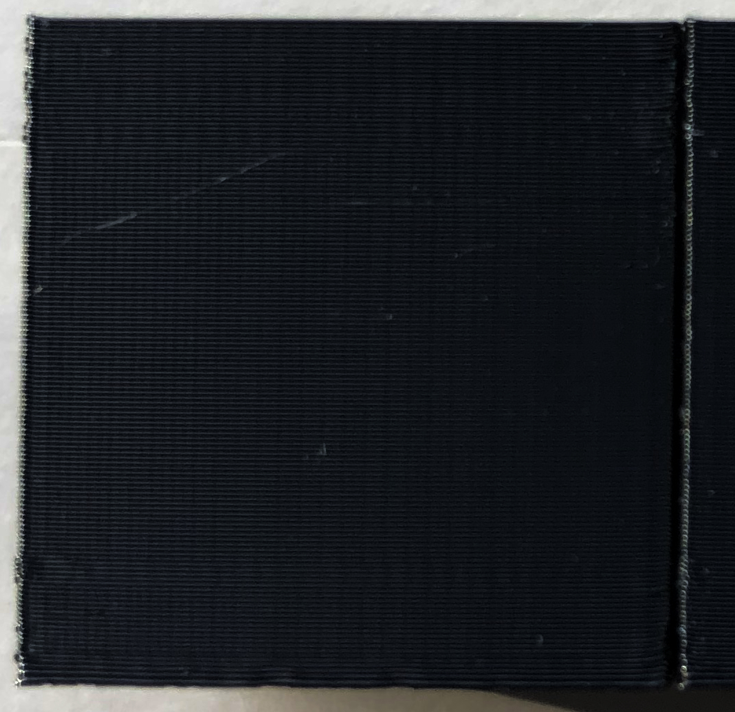
For those who wonder why they have not seen VFA's on their prints, they are probably present in every single mk3 print but can hide with matte filaments and flat lighting. The images I have been posting are lighted to enhance specular surface reflection. In flat lighting, the VFA's are not as apparent. You can almost hide them with flat lighting. If you are printing with a more matte material, you might not realize they are happening. PETG's glossy surface finish makes the VFA's pop, but even flat lighting on PETG hides things...
Take a look at your print surfaces and pay attention to the specular reflection to see the VFA's
Here is the 1st cube in PETG with flat light.
Also, almost everyone who I ask to choose the "best" cube selects the double glitched one. It look more uniform. If I can't make the VFA go away in my tuning experiments, maybe intentionally triple glitching the curve would be an even nicer looking solution --- even if pedantically wrong.
VFA's fixed via modified waveform
I now have one viable solution that fixes y-axis VFA's. Based on my earlier "double glitch" results with almost everyone selecting the double-glitched cubes as looking best, we now have a means of hiding Y-axis VFA's.
I glitch the sine table at start and end of 1/4 wave. An optional mid 1/4 wave glitches don't create a visible VFA line, but smooths the other VFA's a bit more. This results in more numerous, but much finer VFA's. Unfortunately the mid-1/4 glitch destablizes stealth mode motion. So, I am currently not using the mid 1/4 glitch.
The visual result is most people will find y-surfaces smoother and more uniform in appearance. I have also glitched the x-axis, but VFA's on that axis are much milder due to lower motion resistance on that axis. We see VFA's more severely on y-axis because the carriage requires more torque to move. The torque losses at current crossover + higher motion resistance makes the y-carriage briefly stop and suddenly catch back up during stepper cycling. That periodic pause is what creates the VFA's. By adding waveform glitches, I create more VFA's, but they are less visually objectionable.
[EDIT firmware removed from this post]
So thus far....
1. Trinamic hardware only stores 1/4 of a sine wave and reconstructs the full cycle wave from that 1/4 wave form. Unfortunately, the reconstruction inherently means the value at zero crossing is duplicated and negated. The underlying scheme can never be exactly a smooth zero crossing. We can't change that. The best that can be done is to make the 1st table value a 1 so it crosses zero with values 1, -1. Crossing as 0, 0 makes a larger glitch.
2. Although Prusa firmware 3.5.1 tries to makes the wave table crossing 1, -1, an error in how firmware 3.5.1 intializes sin_start as 0 rather than 1. That little mistake creates a discontinuity at zero crossing that repeats every complete electrical cycle. I have fixed that problem in my firmware.
3. Even with the sin_start corrected to 0 and generated wave table set to begin with 1, we still have the inherent Trinamic waveform reconstruction flaw. We cannot make the zero crossing be 2, 1, 0, -1-2 the best we can manage is 3, 2, 1, -1, -2, -3. That is because the zero crossing is created by replicating and negating the 1st table value.
I might be able to mitigate that using the hysteresis settings, but don't yet know whether it can be completely hidden. I suspect it cannot.
4. Increasing the number of VFA events during the stepper cycle, makes y-surface finish appear smoother and more uniform to human observers. VFA's do not significantly alter geometry and size of printed objects. They only makes the surface finish uglier. If I cannot completely tune out the Trinamic zero crossing glitch, this is a viable solution.
void tmc2130_set_wave(uint8_t axis, uint8_t amp, uint8_t fac1000)

{

// TMC2130 wave compression algorithm

// optimized for minimal memory requirements

//  printf_P(PSTR("tmc2130_set_wave %hhd %hhd\n"), axis, fac1000);

  if (fac1000 < TMC2130_WAVE_FAC1000_MIN) fac1000 = 0;

  if (fac1000 > TMC2130_WAVE_FAC1000_MAX) fac1000 = TMC2130_WAVE_FAC1000_MAX;

  float fac = 0;

  if (fac1000) fac = ((float)((uint16_t)fac1000 + 1000) / 1000); //correction factor

//  printf_P(PSTR(" factor: %s\n"), ftostr43(fac));

  uint8_t vA = 0;                //value of currentA

  uint8_t va = 0;                //previous vA

  int8_t d0 = 0;                //delta0

  int8_t d1 = 1;                //delta1

  uint8_t w[4] = {1,1,1,1};      //W bits (MSLUTSEL)

  uint8_t x[3] = {255,255,255};  //X segment bounds (MSLUTSEL)

  uint8_t s = 0;                 //current segment

  int8_t b;                      //encoded bit value

    int8_t dA;                     //delta value

  int i;                         //microstep index

  uint32_t reg = 0;              //tmc2130 register
uint8_t sin_start_glitch = 6; //kuo greather than zero ehnances start quarter glitch
uint8_t sin_mid_glitch = 0; //kuo higher than 1 stops y-carriage motion
uint8_t sin_end_glitch = 6; //kuo greather than zero creates end quarter glitch
if (axis == 1)
{
//kuo special set up y-axis to glitch.
amp = 247;
tmc2130_wr_MSLUTSTART(axis, sin_start_glitch, amp - sin_start_glitch);
}
else
{
//kuo other axes set up for smoothest sine
tmc2130_wr_MSLUTSTART(axis, 1, amp); // sin_start of 1 creates smoother zero crossing
}
for (i = 0; i < 256; i++)
{
if ((i & 0x1f) == 0)
reg = 0;
// calculate value
if (fac == 0) // Kuo TMC wave
if (axis == 1)
{
//quad glitched y axis
if (i < 128)
vA = (uint8_t)round((amp - 1 - sin_start_glitch - sin_mid_glitch) * sin((2 * PI * i + PI)/1024) + 1); //Kuo 1st 1/8 sine wave table including forced 1 at sin_start
else
vA = (uint8_t)round((amp - 1 - sin_start_glitch) * sin((2 * PI * i + PI)/1024) + 1); //Kuo 2nd 1/8 sine wave table including forced 1 at sin_start
}
else
// other axes get clean sine wave
vA = (uint8_t)round((amp - 1) * sin((2 * PI * i + PI)/1024) + 1); //Kuo modified sine wave table including force 1 at sin_start
// vA = (uint8_t)((amp+1) * sin((2*PI*i + PI)/1024) + 0.5) - 1; //Prusa 3.5.1 default TMC wave
else // power modified wave
vA = (uint8_t)round(((amp - 1) * pow(sin(2 * PI * i/1024), fac)) + 1); //Kuo pow sine wave with forced 1 at sin_start
dA = vA - va; // calculate delta
va = vA;
b = -1;
if (dA == d0) b = 0; //delta == delta0 => bit=0
else if (dA == d1) b = 1; //delta == delta1 => bit=1
else
{
if (dA < d0) // delta < delta0 => switch wbit down
{
//printf("dn\n");
b = 0;
switch (dA)
{
case -1: d0 = -1; d1 = 0; w[s+1] = 0; break;
case 0: d0 = 0; d1 = 1; w[s+1] = 1; break;
case 1: d0 = 1; d1 = 2; w[s+1] = 2; break;
default: b = -1; break;
}
if (b >= 0) { x[s] = i; s++; }
}
else if (dA > d1) // delta > delta0 => switch wbit up
{
//printf("up\n");
b = 1;
switch (dA)
{
case 1: d0 = 0; d1 = 1; w[s+1] = 1; break;
case 2: d0 = 1; d1 = 2; w[s+1] = 2; break;
case 3: d0 = 2; d1 = 3; w[s+1] = 3; break;
default: b = -1; break;
}
if (b >= 0) { x[s] = i; s++; }
}
}
if (b < 0) break; // delta out of range (<-1 or >3)
if (s > 3) break; // segment out of range (> 3)
//printf("%d\n", vA);
if (b == 1) reg |= 0x80000000;
if ((i & 31) == 31)
tmc2130_wr_MSLUT(axis, (uint8_t)(i >> 5), reg);
else
reg >>= 1;
// printf("%3d\t%3d\t%2d\t%2d\t%2d\t%2d %08x\n", i, vA, dA, b, w[s], s, reg);
}
tmc2130_wr_MSLUTSEL(axis, x[0], x[1], x[2], w[0], w[1], w[2], w[3]);
}
If anyone wishes to test for themselves but does not have a means of compiling firmware, I am attaching my experimental firmware. Flashing and testing is at your sole risk.
Print baseline test objects with standard firmware, then flash and reprint using the experimental firmware.
Sorry, there isn't a menu option to turn my xy sine wave modifications on/off
Stealth mode should be used with caution. Printer is more prone to layer shifts if sine table glitches are too big. I have made the glitches small enough to use stealth mode on my Mk3, but I suggest using standard mode for testing.
Test firmware is based on 3.5.1 with following mods
- Modified sine table for x and y axes to hide VFA's. This is active only if linearity correction is OFF for x and y axes.
- z and e axes are not "glitched" in this firmware. They only had their zero crossings cleaned up.
- Corrected sine table and sin_start to have 1, -1 transitions.
- N7 mesh bed leveling (if requested in startup g-code, otherwise 3 x 3 is still default)
- Fast, single touch rather than 3 touches/point during mesh bed leveling.
- PWM fix to reduce nozzle cooling fan whine
- Easy to see that my test firmware is running because it reports printer as "Bunny Science Mk3"
Re: Fine Vertical Artifacts / Trinamic Chop Tuning, Any Effect?
I removed the test firmware with fixed glitch parameters in prior post.
If someone indicates a desire to test this on their own printer, I will post a version that allows setting of y-axis glitch, and hysteresis parameters via experimental M-codes.
Setting via m code allows a lot more flexibility for testing.
Re: Fine Vertical Artifacts / Trinamic Chop Tuning, Any Effect?
Attached in this post is my customized firmware based on 3.5.1
Has the following changes.
- part fan whine PWM fix
- 7 x 7 mesh bed leveling (only if G80 N7 instead of G80 in custom start G-code. Otherwise does standard 3 x 3 mesh)
- Fast single touch mesh bed sampling
- Corrected a slight error in Prusa Trinamic stepper wave table initialization
- Implemented experimental G-codes for Trinamic stepper tuning (M919, M920, M921, M922, M923)
- Indicates custom firmware is running by identifying printer as Bunny Science Mk3 or Bear Printer
M919 set toff
M920 set hstr
M921 set hend
M922 set tbl
The above can handle only ONE specified axis per command. You can't set XY and Z in a single command.
example setting to default hysteresis values for Y-axis
M919 Y3
M920 Y5
M921 Y1
M922 Y2
M923 set Y axis sine table
takes three glitch parameters S H E
S is amount to glitch start of sine quarter wave
H is amount to glitch middle of quarter wave . This must be 0 or 1. Higher values stall the stepper.
E is amount to glitch end fo quarter wave.
Only affects y-axis.
example setting for cleanest Y sine wave (no glitching)
M923 S0 H0 E0
Example for Y surface sine wave glitch setting. My mk3 produces best looking y-surface with S8 and E7.
The most important seems to be getting S(tart) to 8. E(nd) has much smaller effect.
M923 S8 H0 E7
NB: glitching both ends of sine wave by more than about 2 or 3 causes stealth mode layer shifts.
Must test if leaving E0 but setting S8 allows stealth mode to work.
Unzip to obtain firmware hex.
