Crazy indirect filament sensor mod?
I need some more eyes on this before I print and test it.
My goal was to avoid the need for firmware editing, to minimise the requirement for printing of lots of new parts, and to avoid leaving a hole for filament to get jammed in if an indirect sensor was used elsewhere in the filament path.
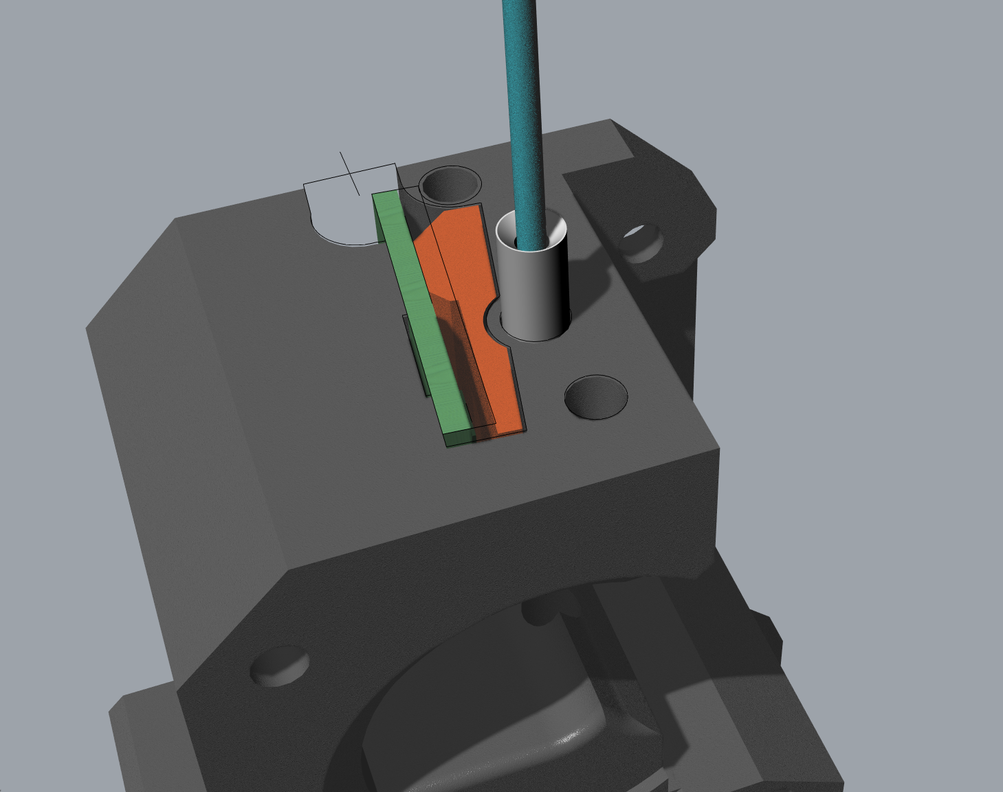
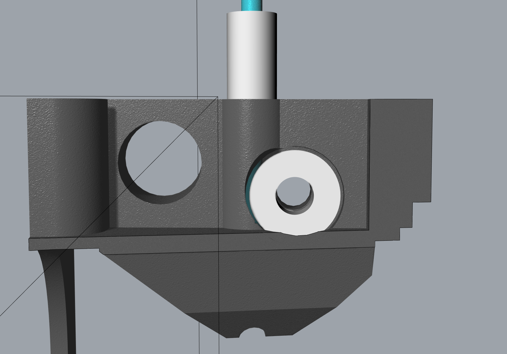
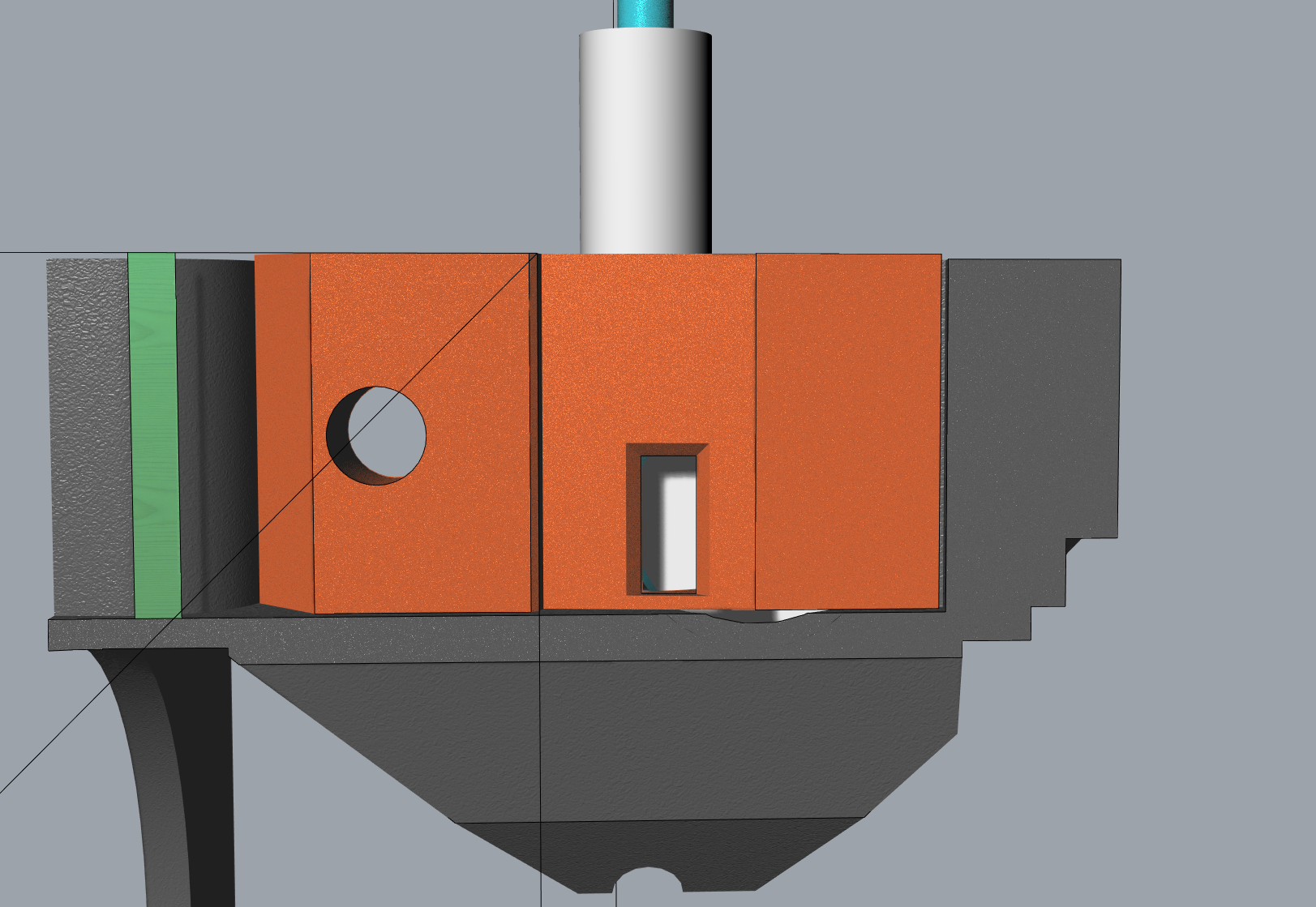
The idea is that a flanged bearing runs against the filament in about the same spot that the filament sensor "looks". The filament sensor looks through a small window at the side of the rotating flange. The direction is the same as the filament so no firmware mod is required. The bearing is held in place with an M3, 8mm countersunk screw, and a "wedge". The wedge is held in place by the filament sensor bolt, and will provide a tiny bit of adjustability, and gives a spot for the end of the bearing screw to rest.
This design means that we would only have to print out a new extruder body, and the wedge. No firmware editing is required. Hardware needed should be an F63zz bearing (IIRC) and an 8mm m3 screw. Everything else should still fit.
Re: Crazy indirect filament sensor mod?
Solutions for the “filament detection problem” have already been discussed in this forum. Some sort of rotary encoder / encoder wheels (which is also basically your idea) seems to be the best solution.
I have no idea why Prusa is not implementing something like this. The mmu2 unit has an inductive sensor with a metal ball. That’s even worse than the optical sensor because a tip with a string is causing obviously problems.
Re: Crazy indirect filament sensor mod?
Well, parts are printed (including a very nice extruder body. Apparently my Prusa is well dialed in. :D). Wedge and sensor fit snug as a bug. Now I’m just waiting on a bearing and some countersunk screws.
The filament path is very constrained, so there should be no chance for filament escaping into the sensor cavity.


