Bolt-On Gearbox Extruder Experiment
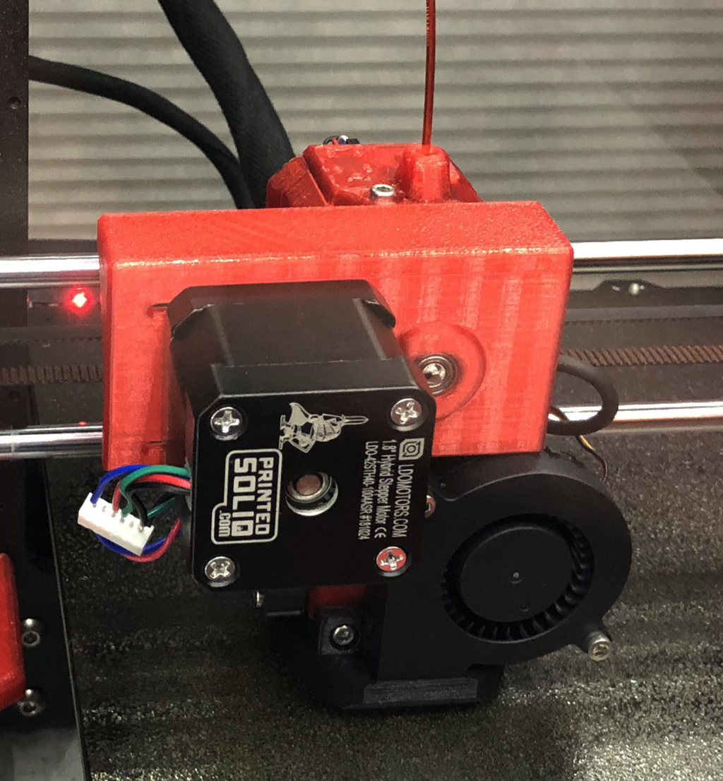
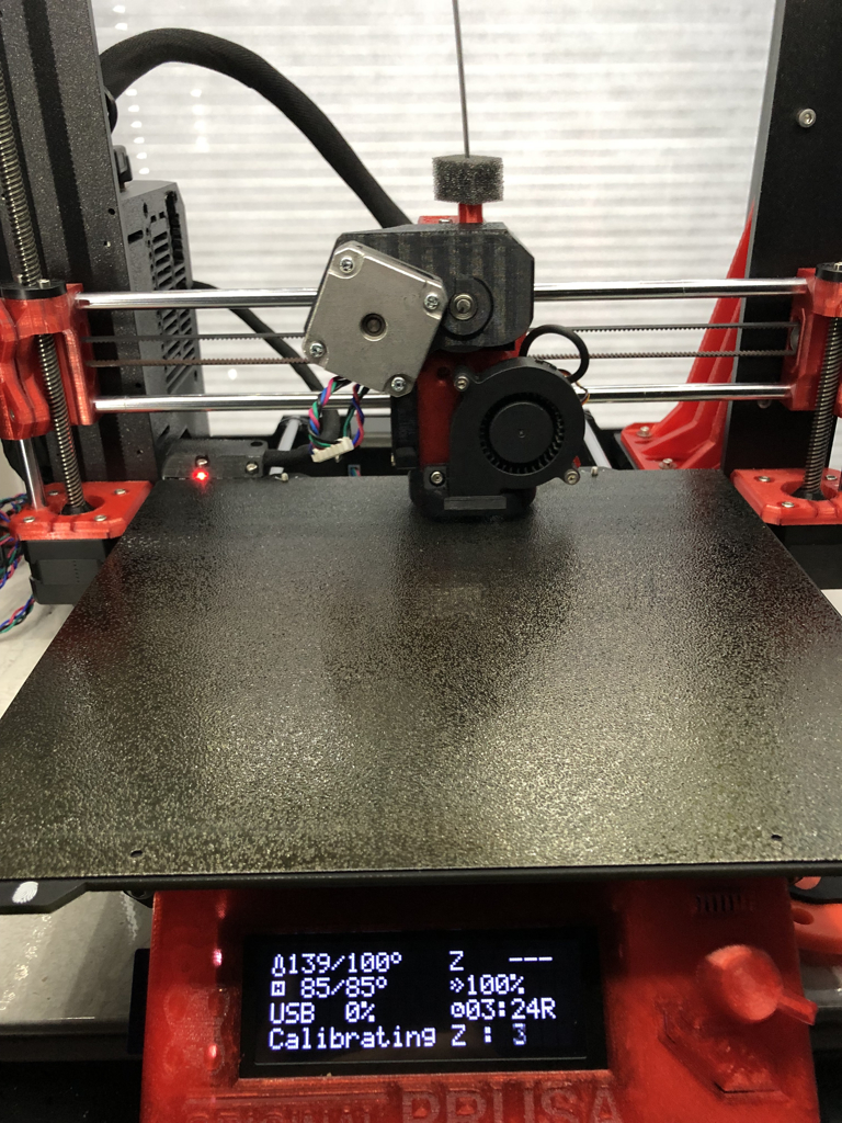
After seeing impressively uniform test results from the geared Bondtech extruder, I wondered how much the effect was due to the gearing vs lighter, tighter extruder design. To do a quick test, I cobbled together a crude 1:3.5 belt drive gear adapter. Motor goes onto the gear adapter, a shaft extends out of the adapter and and the whole thing mounts as a NEMA 17 bolt pattern motor.
This is bigger, heavier, uglier, and out of balance, and long moment armed compared to a proper geared extruder. Basically, other than changing gearing I was making my extruder worse by almost every other measure.
It's basically a normal 16 tooth pulley driving a 56 tooth pulley via a closed loop. Stole the big tooth pulley from the Skelestruder design and crammed it into a NEMA 17 emulating carrier with 5 mm shaft and bearings.
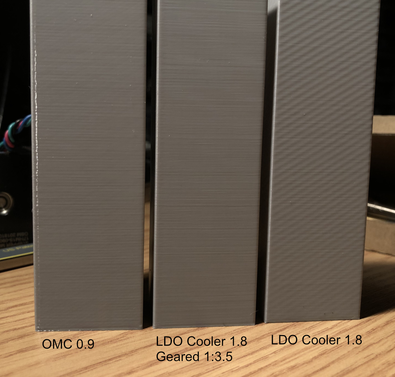
How did this monstrosity do? I used the same 1.8 degree LDO Cooler stepper with and without the gearbox. The LDO Cooler 1.8 motors previously tested the absolute worst in terms of extruder non-uniformity diagonal waves on my test towers. Yes, they are worse than the stock Prusa LDO extruder motor. Would such a non-uniform motor be helped by gearing it down? Remember, I'm also ruining a lot of other extruder characteristics by bolting on a heavy motor farther out and adding the weight of my gearbox.
On the left is an OMC 0.9 motor - one tested to outdo even a Moons 0.9 (if the OMC is linearity corrected). That tower has minimal diagonal wave.
In the middle is LDO Cooler 1.8 motor with 1:3.5 gearing.
On the right is same LDO Cooler 1.8 but directly driving the extruder.
I think this is pretty good evidence that gearing down the extruder motor makes a huge improvement in extruder uniformity. This was with just a heavy primitive gearbox.
That gearbox monstrosity is printing a more compact version of itself now. Paired with a pancake motor, it should get down close to the weight of a normal direct drive motor. We already know that pancake motors can drive geared extruders successfully on the Mk3's. This is just a ghetto way of doing it.
Yes, it is possible to convert a normal direct drive extruder into a more uniform, geared-down extruder by bolting on an external gearbox.
My firmware branch has been updated to support 1:3 and 1:3.5 gear ratios on the extruder.
Re: Bolt-On Gearbox Extruder Experiment
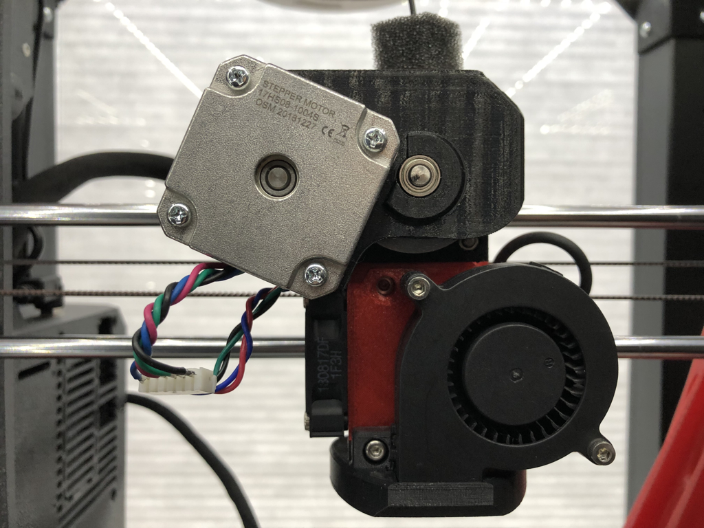
After the success of the text gearbox, I designed a prettier, slim version. With a pancake motor, it is smaller and lighter. 177 gms total. Bolts in like a normal NEMA 17 motor. Installation on printer was quick, three bolt job with my modified easy motor service Bear extruder.
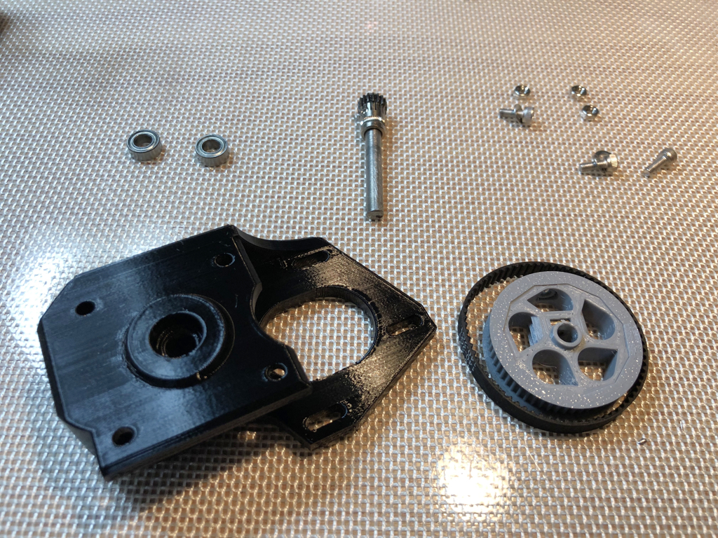
Here are the bitlets. The large gear and spacers are poached from the Skelestruder files. Shaft was cut and flats ground with a Dremel.
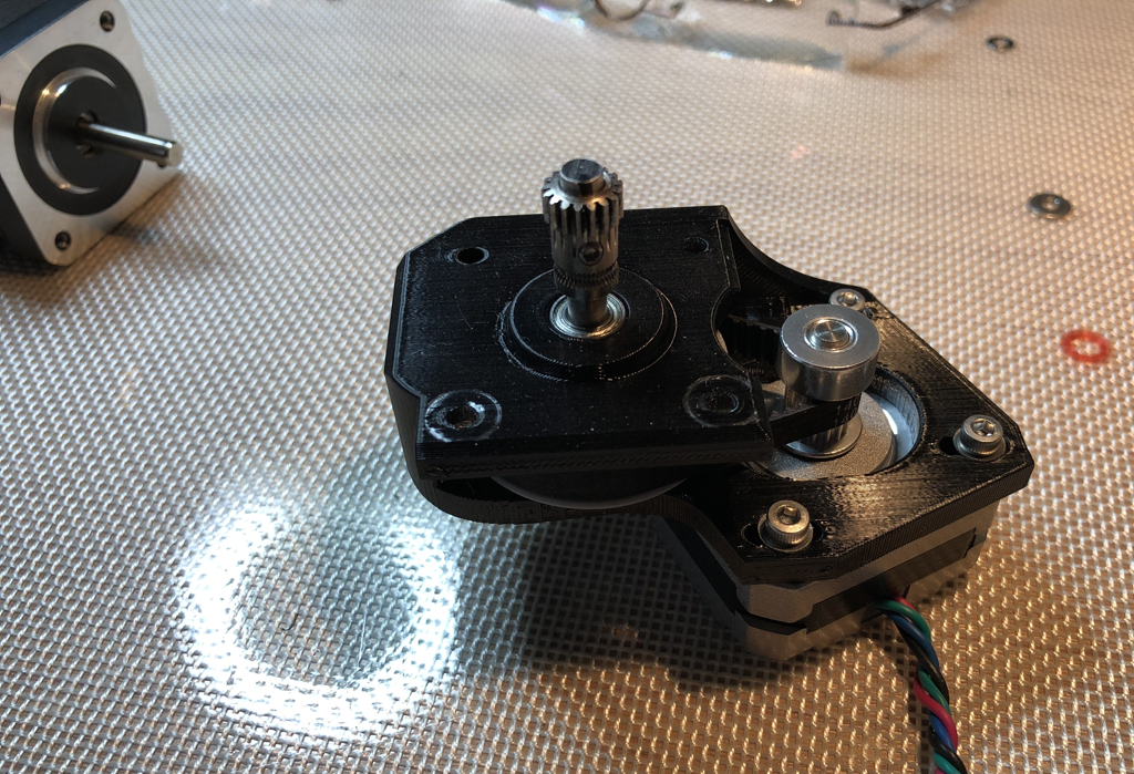
Partially assembled. Motor is OMC 17HS08-1004S 1.8 degree short height unit (1.0 amp, 140 gm). A 0.9 degree pancake will be tested when it arrives.
Re: Bolt-On Gearbox Extruder Experiment
The OMC 17HS08-1004S motor depicted above is too low torque for uniform extrusion across larger objects.. A higher torque unit like the LDO used with the Bondtech extruder is probably going to be needed. Full size motors work with this, but that is a lot of weight to be cantilevered.
Re: Bolt-On Gearbox Extruder Experiment
Guy, most of what you do is beyond where I want to go with my 3D printing, but I wanted to let you know it's fascinating stuff.
and miscellaneous other tech projects
He is intelligent, but not experienced. His pattern indicates two dimensional thinking. -- Spock in Star Trek: The Wrath of Khan
Re: Bolt-On Gearbox Extruder Experiment
Thanks. I do enjoy exploring the limits. It's more fun if there is someone with whom to share.
Re: Bolt-On Gearbox Extruder Experiment
Yes keep posting these experiments you do.
Not only is it fascinating but it can lead to genuine improvements to the printer.
Top job and the way you implemented it is very nice.
Re: Bolt-On Gearbox Extruder Experiment
Guy did you consider a coaxial planetary reduction gear set up? that would put the stepper back in the middle... it is fun watching your experiments
Re: Bolt-On Gearbox Extruder Experiment
Fascinating - I'm actually seriously contemplating building a skelestruder now since it has a reduction 🙂
Re: Bolt-On Gearbox Extruder Experiment
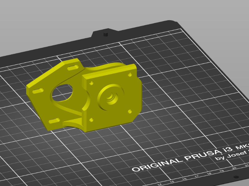
In case someone wants to play along, attached is STL for my gearbox adapter.
Print in PETG, 3 perimeters, 25-30% gyroid, no support, in this orientation...
You will also need
5 mm shaft rod
2 x 1050ZZ bearings
1 continuous loop 140-2GT-6 Timing Belt
M3 square nut
M3 hex nuts & bolts various lengths.
M3 set screw
M3 washers
From Skelestruder project, print his large, gear wheel and spacers in PETG
SP_spacer_v1a4.stl
SP_Tread56_r1.stl
SP_Wheel_r1.stl
If you need more instructions and exact dimensions, you shouldn't be trying this experiment.
This is mostly an exploration of how much gearing improves motor uniformity. It's not going to be a practical, bolt-on upgrade.
Gearbox requires work, parts, and ideally a pancake motor that will cost as much as a 0.9 degree OMC motor.
By just doing the $20 OMC motor you already get about 80% of the Bondtech extruder's improvement.
This gearbox is very unlikely to match the Bondtech extruder.
It might just barely beat out an 0.9 OMC motor upgrade, but not practical at about $50 (if you already have some of the hardware)
I started this while contemplating the Skelestruder vs Bondtech extruders. I really prefer to print and modify my own parts, but it is clear that gearing down the motor is a benefit.
Planetary gears I couldn't make small enough to get the moment arm shorter. Because x-axis moves only in x-plane, I think midline placement is less important that getting mass closer to rods. Reducing motor mass is also desired. On the other hand, I'm surprised at how well the Prusa is tolerating a full size motor mounted on this contraption.
Another way to look at this experiment is a stepping stone to the Skelestruder. You need mostly the same "vitamins"
We have many different ways to improve extruder uniformity over the stock designs.
1. Just a 0.9 degree motor swap
2. Skelestruder
3. Bondtech upgrade
4. Crazy gearbox bolt-on (stupid but works)
Why settle for just stock performance?
Re: Bolt-On Gearbox Extruder Experiment
Add number 5 to the list: a flex-shaft extruder... Just had this pop up in my feed:
Re: Bolt-On Gearbox Extruder Experiment
Looking at the MK3S motor plate.....
I think it would be possible to integrate the 1:3.5 gearbox as part of the MK3S motor plate. Compared to a separate gearbox, that would bring the motor about 6 to 8 mm back towards the rods. That is enough to reasonably re-use the stock full size motor. For even more weight savings, a strong pancake motor would be even better.
I already showed that gearing down the extruder helps with uniformity. If the stock motor were utilized, a gearbox mod would be super cheap. It would be three printed parts, a shaft, two bearings and a closed loop belt. I'm thinking belted because printing 3:1 intercalated gearing with enough accuracy would be a challenge.
I think there are the step files for the MK3S extruder?
If we did mods of extruder parts, we have new interesting variants.
Geared Bear - more difficult geometry to print with gearbox integration.
Geared MK3S - easier due to separate motor plate
Re: Bolt-On Gearbox Extruder Experiment
After a couple days of redesigning the gearbox, I have reduced the distance that the motor is in front of normal mounting position. Gearbox now holds motor just 15.5 mm forward from normal position. That's close enough to consider using a full size a normal motor. It's definitely good enough for a pancake unit as a permanent gearbox addition. Gearbox is also much stiffer than the first few rounds.
I haven't gotten a 0.9 degree pancake working properly. Also, improved motor positioning means a shorter shaft motor is needed to avoid hitting x-axis mounts with motor shaft.
Meanwhile, an earlier version of my gearbox is working well with the OMC (Stepperonline) 17HS10-0704S 1.8 degree motor. (That's the motor that supplied with my newly arrived Bondtech extruder). It is short shafted and light.
I see essentially no diagonal waves on my ecore tower with the gearbox + OMC 1.8 degree pancake. I tempted to leave this on the printer longer term. If I can get this quality extrusion and retain the easy service / experimentation capability of my modified Bear extruder.
Currently printing what I hope will be a good design for the gearbox using an earlier version of itself. 😀
Re: Bolt-On Gearbox Extruder Experiment
I wonder how much of this improvement is from the belt as opposed to the gear reduction. This is one of the reasons turntables and tape decks used belt drives - it helped reduce the motor non-uniformity that would manifest as wow and flutter in the audio.
Would be easy to verify by only printing new pulleys - if the belt is the reason, you would not see any patterns when using a 1:1 pulley ratio. If it's the reduction, then you would.
Re: Bolt-On Gearbox Extruder Experiment
Must be a way to do this with direct planetary gears ...
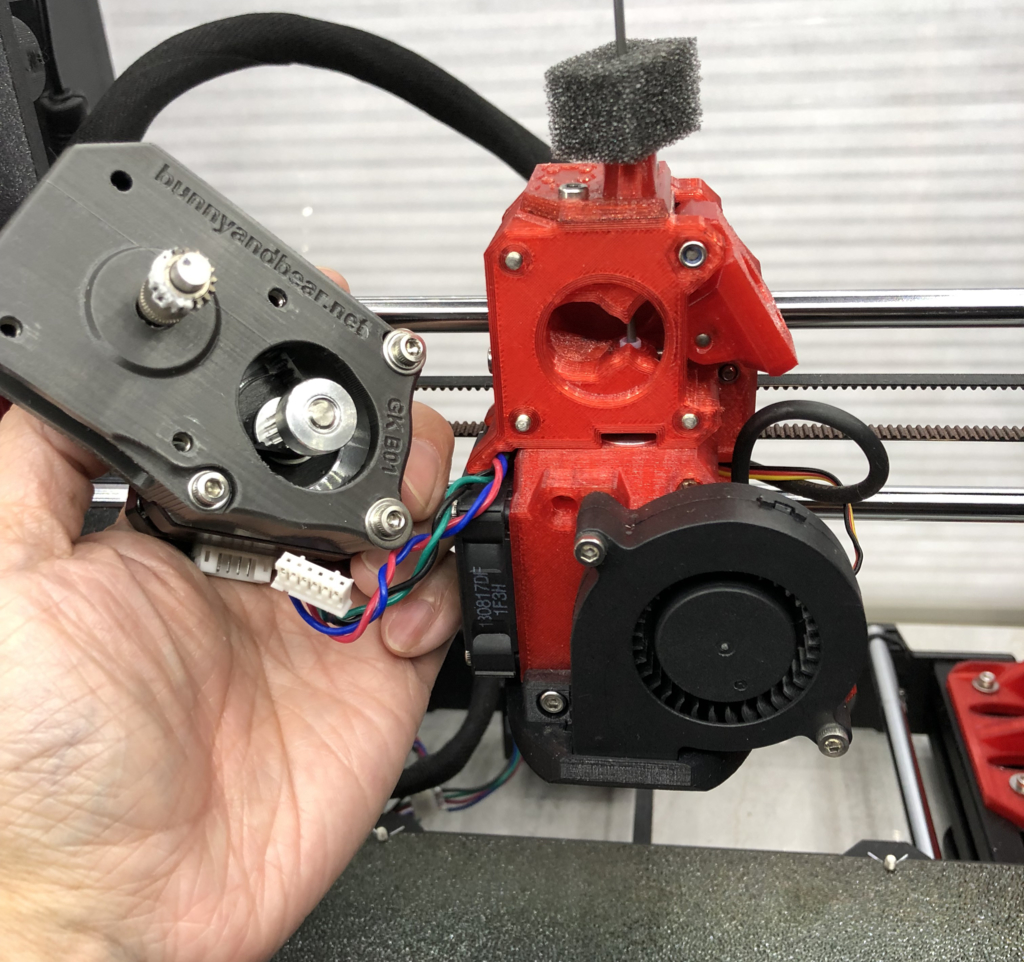
Installed
The latest gearbox has the best fitment yet. Installed and running some print jobs...
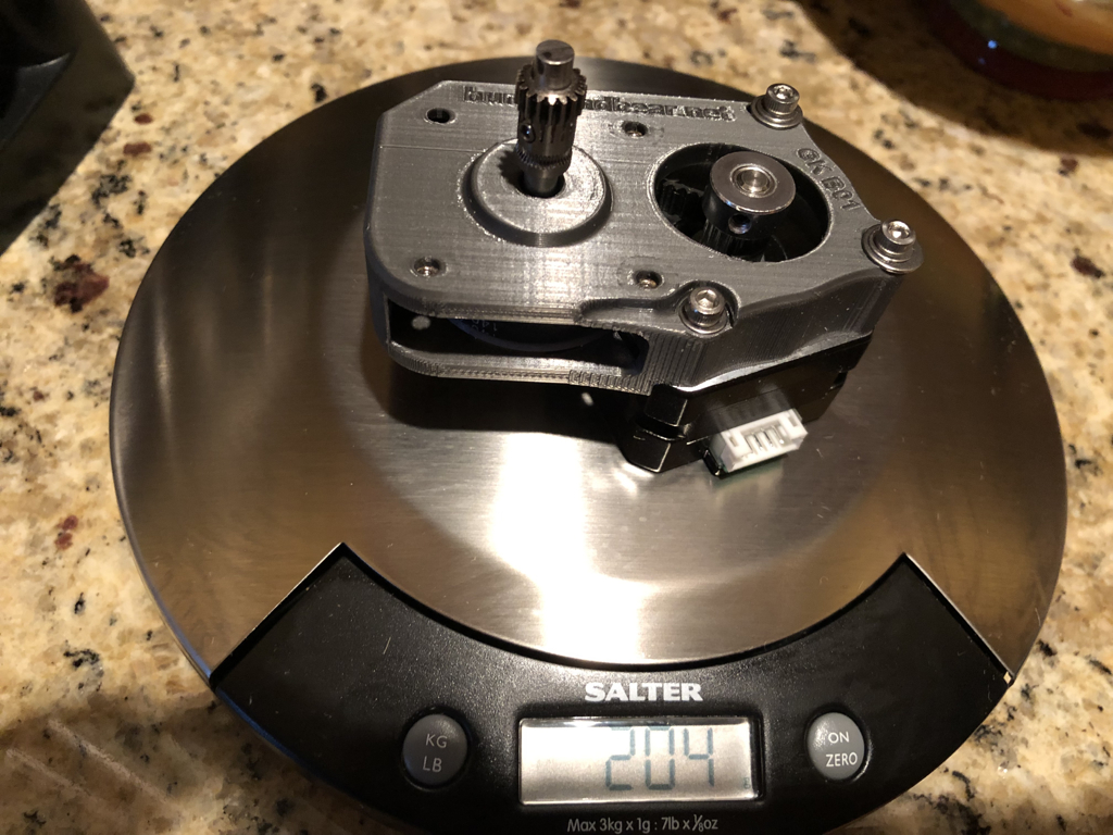
Mass is 204 gm vs my usual motor's 277 gm
With a pancake motor, it's definitely lighter and the compact design keeps it feeling less imbalanced.
Printer axes don't sound any different with it installed. Extruder motor does make a soft, high pitch note during retractions & layer starts.
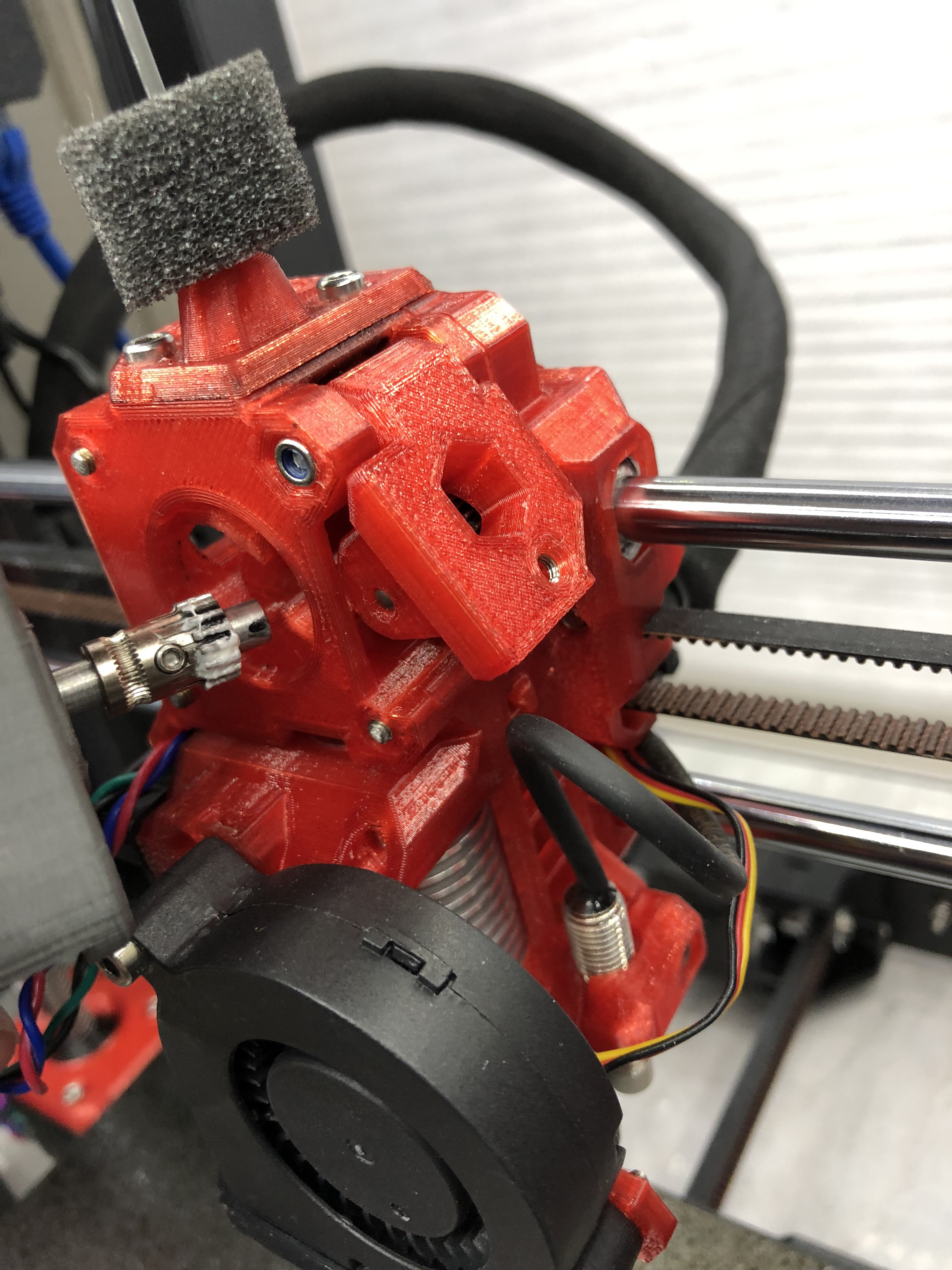
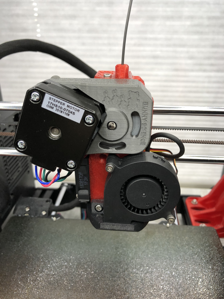
installed 2
With my fast, three bolt service Bear extruder, installation was as quick as a regular motor - 5 to 10 minutes. On normal setups, motor swaps take a bit longer, but this installs just like a regular motor.
I might have been a little generous with the lithium grease for the Bondtech drive
Here she is, ready to go.
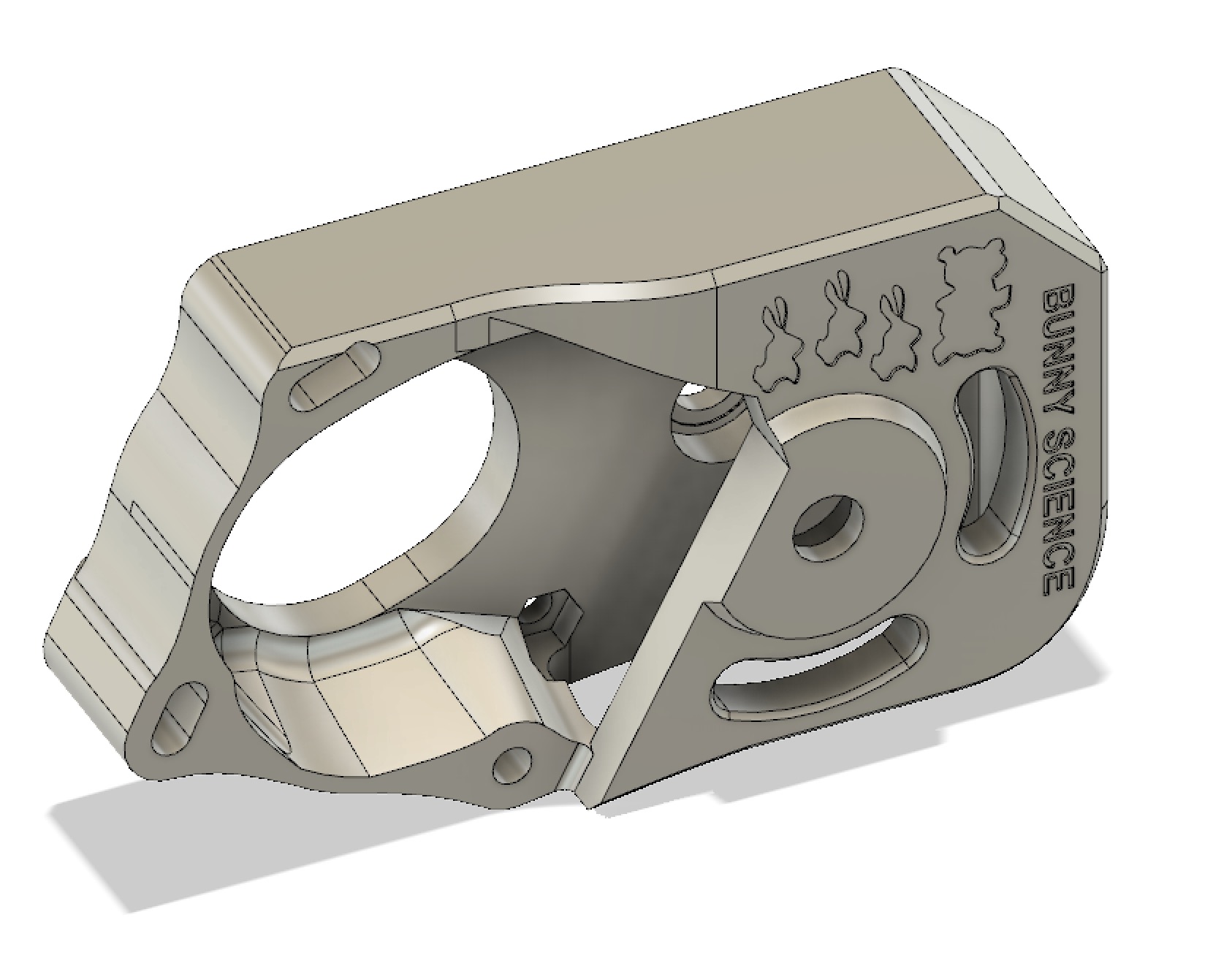
current STL for bunny science gearbox
Here is the PRACTICAL gearbox design
Print PETG, 3 perimeters
30% gyroid
no supports
orient flat top on plate, open bottom up. (The bunnies and bear should look upside down on build plate)
The print does have some challenging overhangs, but the blemishes will be on the interior.
Re: Bolt-On Gearbox Extruder Experiment
Forgive my ignorance, but is the only change that needs to be made when doing something like this to change the E steps per mm? (i.e, it can be done with G-code and does not need a firmware change)
Re: installed 2
I might have been a little generous with the lithium grease for the Bondtech drive
Not to mention the two gears are synchronous and you've only added grease to 1/2 the rotation... 😛 lol.
