Increase Extruder Motor Current
Hello all my extruder motor grabs onto the filament and loads a large revolution of filament.
Once it increases any sort of force affecting the extrusion it skips, It moves the filament for awhile with such ease,
I think that the grip on the filament isn't the problem its just that the force required to pull / push the filament is more than
the motor is getting in current.
How could I increase the motor current?
This will probably require updating and recompiling the firmware, any info on how to do this?
Thanks
Re: Increase Extruder Motor Current
i don't think that the current for your extruder motor is the problem.
check that the pulleye isn't worn out, that it is attached firmly to the motor's shaft and that the extruder springs are tightened enough.
and furthermore: that your spool doesn't act as a brake !
💡 if you still want to compile the firmware, use allen.d's script. it makes a lot of things much easier... especially configuring the correct arduino version to the proper, required boundary conditions.
➡ the motor current for the extruder is defined through these values inside the Configuration_prusa.h file (which is in fact a copy of the 1_75mm_MK2-RAMBo13a-E3Dv6full.h out of the variants folder), around line #162:#define DEFAULT_PWM_MOTOR_CURRENT {270, 830, 450} // {XY,Z,E}.
#define DEFAULT_PWM_MOTOR_CURRENT_LOUD {540, 830, 500} // {XY,Z,E}
😕 by the way: when using the multi material kit, the value for the extruder is increased to 700.... personally i wouldn't exceed this value when you mess around with the E-values at the given lines, even in high-power mode.
dem inscheniör is' nix zu schwör...
Re: Increase Extruder Motor Current
when using the multi material kit, the value for the extruder is increased to 700....
No, it's 750 (or the desired value) and only during a filament change. It then reverts to 550.
And to adjust the digipots, you can use the M907 command:
M907 E750 for example.
This command can be included in the start GCode section. But be aware that if your motors get hot, so will the drive shaft and pulley. If the pulley gets above 55 degrees, then you are in danger of melting the filament; and even at that temp the filament will soften and will mess up extrusion.
Peter
Please note: I do not have any affiliation with Prusa Research. Any advices given are offered in good faith. It is your responsibility to ensure that by following my advice you do not suffer or cause injury, damage…
Re: Increase Extruder Motor Current
...
And to adjust the digipots, you can use the M907 command...
just to avoid confusion: only the BIG-Rambo (RAMBo10a), previously used for the i3 (MK2), has had digipots.
i've thought that the Mini-Rambo uses digipots as well, but during the research for my clone, i needed to revise my point of view.
the actual one, with the Mini-Rambo (RAMBo13a) generates the control voltages for the stepper motors through three dedicated pwm pins (xy -> pin#46, z -> pin#45 and e -> pin#44) and thre rc-filters (each: 3x 10k Ohm, 2x 1µF).
so our actual i3 MK2(S) doesn't have digipots any more.
@Peter: do you know if our prusa firmware interprets the M907 command as M906 then (which should be the obvious behaviour), or does it simply discard the M907 ?
dem inscheniör is' nix zu schwör...
Re: Increase Extruder Motor Current
Jeff
Apologies, missed your query.
M906 is not implemented, only M907: "M907 Set digital trimpot motor current using axis codes"
The RAMBo 1.3a uses "Digital Trimpots" or Digipots as opposed to analogue trimpots on the RAMPS stepper drivers.
The digital PWM outputs on the pins you mention are converted into an analogue voltage via an RC network and thereafter used exactly the same as the analogue pots.
Peter
Please note: I do not have any affiliation with Prusa Research. Any advices given are offered in good faith. It is your responsibility to ensure that by following my advice you do not suffer or cause injury, damage…
Re: Increase Extruder Motor Current
...The RAMBo 1.3a uses "Digital Trimpots" or Digipots as opposed to analogue trimpots on the RAMPS stepper drivers....
😕 sorry Peter, but at this point i have to disagree (which i neither do often, nor like).
the Big Rambo (rambo10a) uses Digipots, the miniRambo (rambo13a) has no digipot-chip on board and uses the control voltages provided through the PWM and the RC-low pass filters we both mentioned.
if you look inside the Configuration_prusa.h, you can read:
// Motor Current setting for BIG RAMBo
#define DIGIPOT_MOTOR_CURRENT {135,135,135,135,135} // Values 0-255 (RAMBO 135 = ~0.75A, 185 = ~1A)
#define DIGIPOT_MOTOR_CURRENT_LOUD {135,135,135,135,135}
// Motor Current settings for RAMBo mini PWM value = MotorCurrentSetting * 255 / range
#if MOTHERBOARD == 102 || MOTHERBOARD == 302
#define MOTOR_CURRENT_PWM_RANGE 2000
#define DEFAULT_PWM_MOTOR_CURRENT  {270, 830, 450} // {XY,Z,E}

#define DEFAULT_PWM_MOTOR_CURRENT_LOUD  {540, 830, 500} // {XY,Z,E}
#endif
just to make that point clear, the "BigRAMBo" mentioned inside the firmware is the RAMBo 1.0a board, used for the MK1 and is still working inside some printers upgraded from the MK1 to an MK2.
the "RAMBo mini" ist the RAMBo 1.3a board, used in production for the MK2 (and MK2S).
and if you look inside the schematics for the mini-Rambo (RAMBo 1.3a), you won't find any digipot circuit:

and furthermore, if you look at the RAMBo 1.3a board, you won't find any digipot circuit as well:
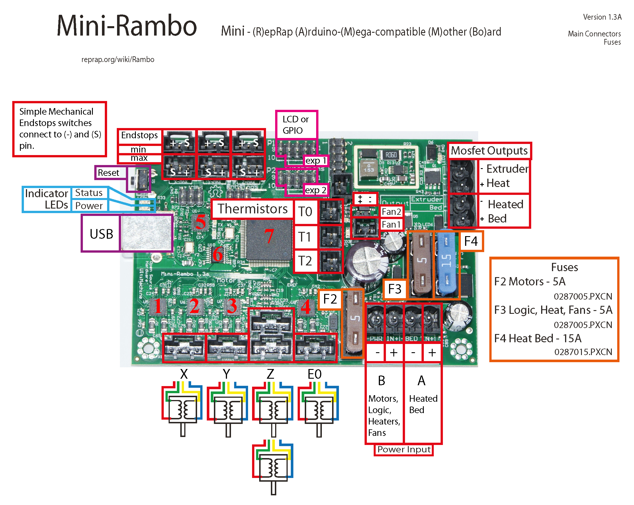
chips #1 to #4 are the A4982 stepper drivers
chip #5 is the atmega32u2 which does the USB interfacing job
chip #6 is an ADUM7441 quad-channel insulator, that insulates the usb circuit from the power potential of the rest of the circuit. without this chip you would have the same ground potential at the usb port as at the power supply... and if you plug in the printer then at your computer (which is usually grounded itself), you'll get into problems because of a big current loop.
chip #7 is the atmega2560, which holds & processes the firmware.
-> so there is no digipot at the RAMBo1.3a board !
dem inscheniör is' nix zu schwör...
Re: Increase Extruder Motor Current
Jeff
I was looking at this again last evening and realised I was wrong. It happens a lot nowadays...
I also realised that the calculation for the M907 command is an almost 1:1 relationship with the actual current (M905 E750 -> 750mA approx).
Thanks
Peter
Please note: I do not have any affiliation with Prusa Research. Any advices given are offered in good faith. It is your responsibility to ensure that by following my advice you do not suffer or cause injury, damage…
Re: Increase Extruder Motor Current
...I was looking at this again last evening and realised I was wrong...
no problem. as i mentioned above, i first thought as well that the prusa MK2 uses digipots (i even ordered a geetech rambo 1.2g with digipots, believing i can get the prusa firmware running at that board...).
dem inscheniör is' nix zu schwör...
Re: Increase Extruder Motor Current
...I was looking at this again last evening and realised I was wrong...
no problem. as i mentioned above, i first thought as well that the prusa MK2 uses digipots (i even ordered a geetech rambo 1.2g with digipots, believing i can get the prusa firmware running at that board...).
oh...shiiiinikies...... dude you just made my heart drop... Are you tellin me i wont be able to use the MKS 1.4 board with the Prusa Firmware for my HARIBO build? ( just ordered it like a week ago... still in transit.)
Re: Increase Extruder Motor Current
Are you tellin me i wont be able to use the MKS 1.4 board with the Prusa Firmware for my HARIBO build?
No, but you will have a lot of work to do in Pins.h and there will be a few "functions" missing (like being able to adjust motor current within GCode).
Peter
Please note: I do not have any affiliation with Prusa Research. Any advices given are offered in good faith. It is your responsibility to ensure that by following my advice you do not suffer or cause injury, damage…
Re: Increase Extruder Motor Current
Are you tellin me i wont be able to use the MKS 1.4 board with the Prusa Firmware for my HARIBO build?
No, but you will have a lot of work to do in Pins.h and there will be a few "functions" missing (like being able to adjust motor current within GCode).
Peter
hmm.....dang man... i should just return it as soon as i get it and purchase the MiniRambo eh? my understanding is... they made sure the board matches the pin layout of the RAMPS 1.4. and the MiniRambo Matches the RAMPS right? So what would be some of the things i shoiuld pay attention to when changing the pin-outs?.. i purchased the MKS because it was supposed to Mirror the Ramps and work with the same firmware config. was that a mistake?
Re: Increase Extruder Motor Current
You might want to have a read of this thread: http://shop.prusa3d.com/forum/improvements-f14/prusa-i3-mk2-my-way--t4047.html
Peter
Please note: I do not have any affiliation with Prusa Research. Any advices given are offered in good faith. It is your responsibility to ensure that by following my advice you do not suffer or cause injury, damage…
Re: Increase Extruder Motor Current
and this post as well (containing some infos on how to get the firmware running at "another board") 
dem inscheniör is' nix zu schwör...
RE: Increase Extruder Motor Current
@jeffjordan
I am in a similar boat with a Hemera extruder on a onld MK2S board. With the extruder vref values how is that calculated? The hemera is a 1.33a motor and I don't know what values are needed for the 450 and 500 factory values. Can anyone help explain the calculation to me? Looking to have a .5 vref for that motor I believe would be correct but the large value doesn't compute. Below is the factory firmware settings I am asking about. TIA for any help.
// Motor Current settings for RAMBo mini PWM value = MotorCurrentSetting * 255 / range
#if MOTHERBOARD == 102 || MOTHERBOARD == 302
#define MOTOR_CURRENT_PWM_RANGE 2000
#define DEFAULT_PWM_MOTOR_CURRENT {270, 830, 450} // {XY,Z,E}
#define DEFAULT_PWM_MOTOR_CURRENT_LOUD {540, 830, 500} // {XY,Z,E}
#define Z_SILENT 0
#define Z_HIGH_POWER 200
#endif