I need assistance in making my kit square
Hello,
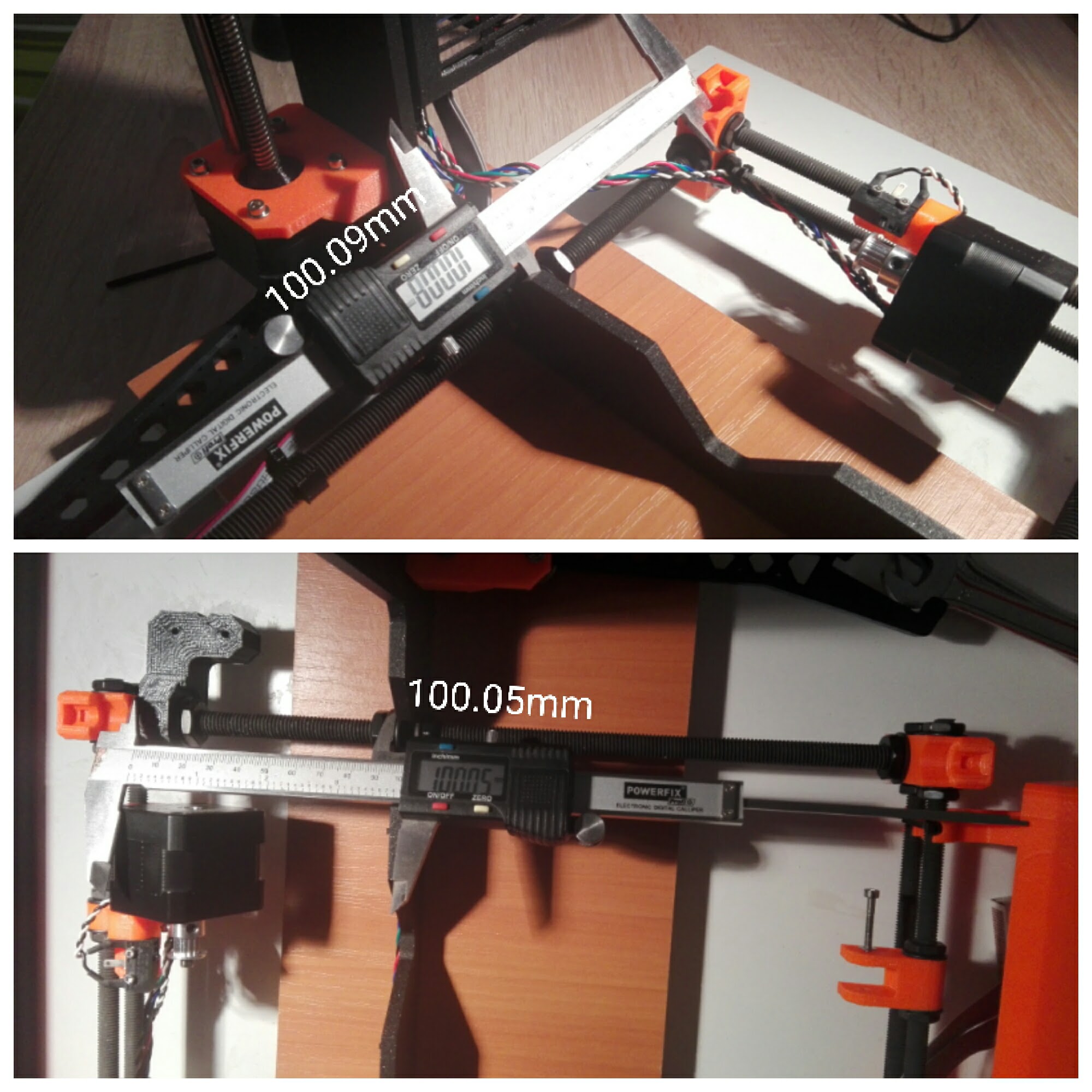
I have taken apart and put back together the printer and this really made sure dimensions are accurate as the manual describes. Now, in the beginning I noticed this too and made adjustments/workarounds to overcome it but after my XYZ calibration fail I decided to make it again as per manual. I have about 100mm (+- <0.1mm) for the ZPlate to the back-feet and I made sure the Y-ThreadedRods are bottomed in the notches of the ZPlate. The SmoothRods are firmly pressed in their designated places in the 4 feet, also all 4 feet are level, pressing opposite feet doesn't raise the other from ground, etc.
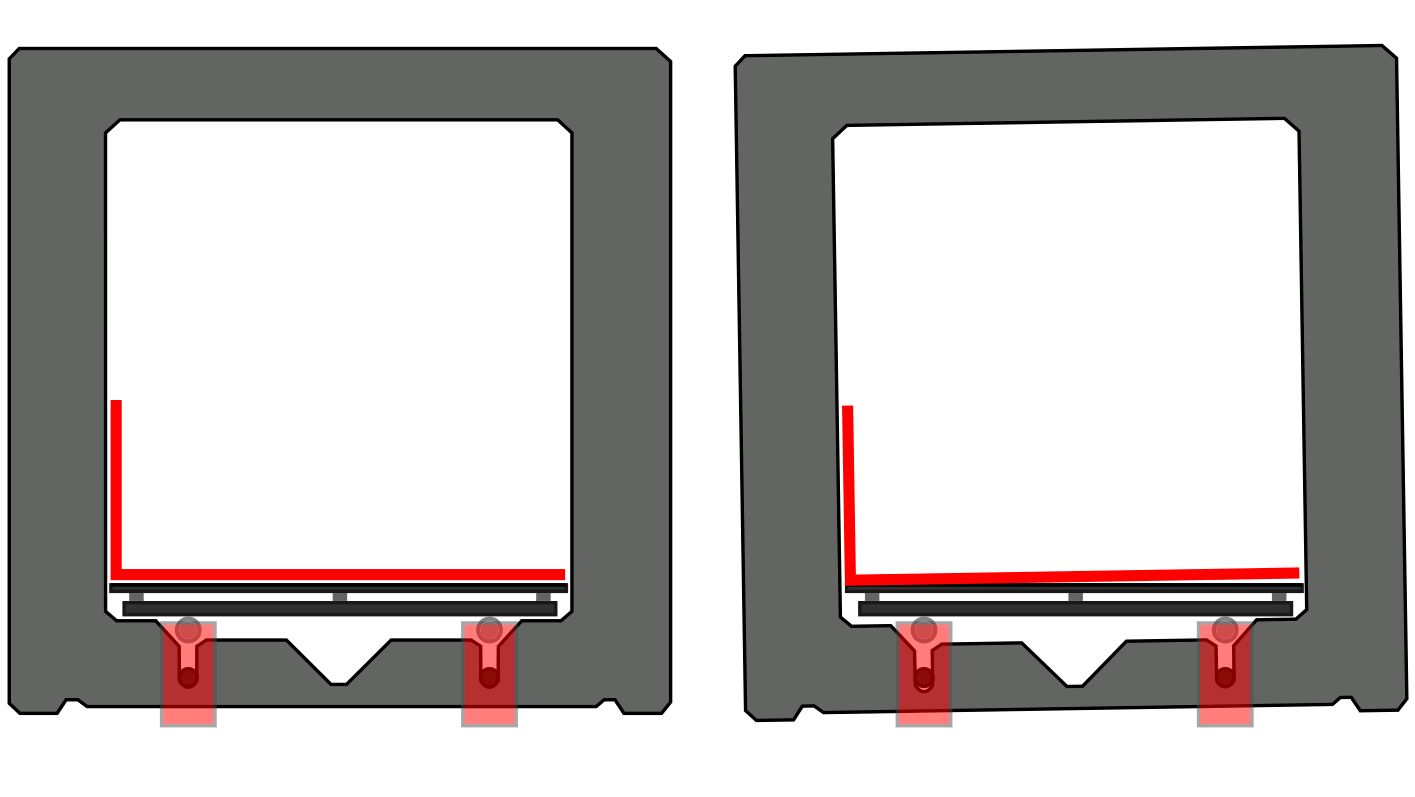
Now the issue is the one you see in the pictures and in the attached sketch. The bed seems slanted and I am not sure that is possible having the Y-Carriage well built, fact confirmed by the measurement of the distance between the bed and the ground. The only conclusion I can make is that the ZPlate is rotated (check sketch) and to overcome this (without going into software) is to rotate it the other way around. If the ZPlate is rotated then the Z axis is too so I won't break any squareness if doing so.
What is your opinion?
I don't know how to upload images here so I will direct you to the G+ post I made on the issue (same question as here): https://plus.google.com/+FlorianFord3DP/posts/68risRFN92c
Re: I need assistance in making my kit square
...
Can't insert images inline so I am tring links:
https://is.gd/Mtn6iu
https://is.gd/btwBki
https://is.gd/OoeEdn
https://is.gd/MRfuxY
you need to use the attachment option at the bottom of the frame. this even allows you to place the pictures inline of your posting, wherever you want.
you can attach up to 3 images, which will be stored at the prusa servers where this board is running (so they'll last, even if you've cleared them from your server or picture hoster).
if you need to show more than 3 pictures, add another posting.
dem inscheniör is' nix zu schwör...
Re: I need assistance in making my kit square
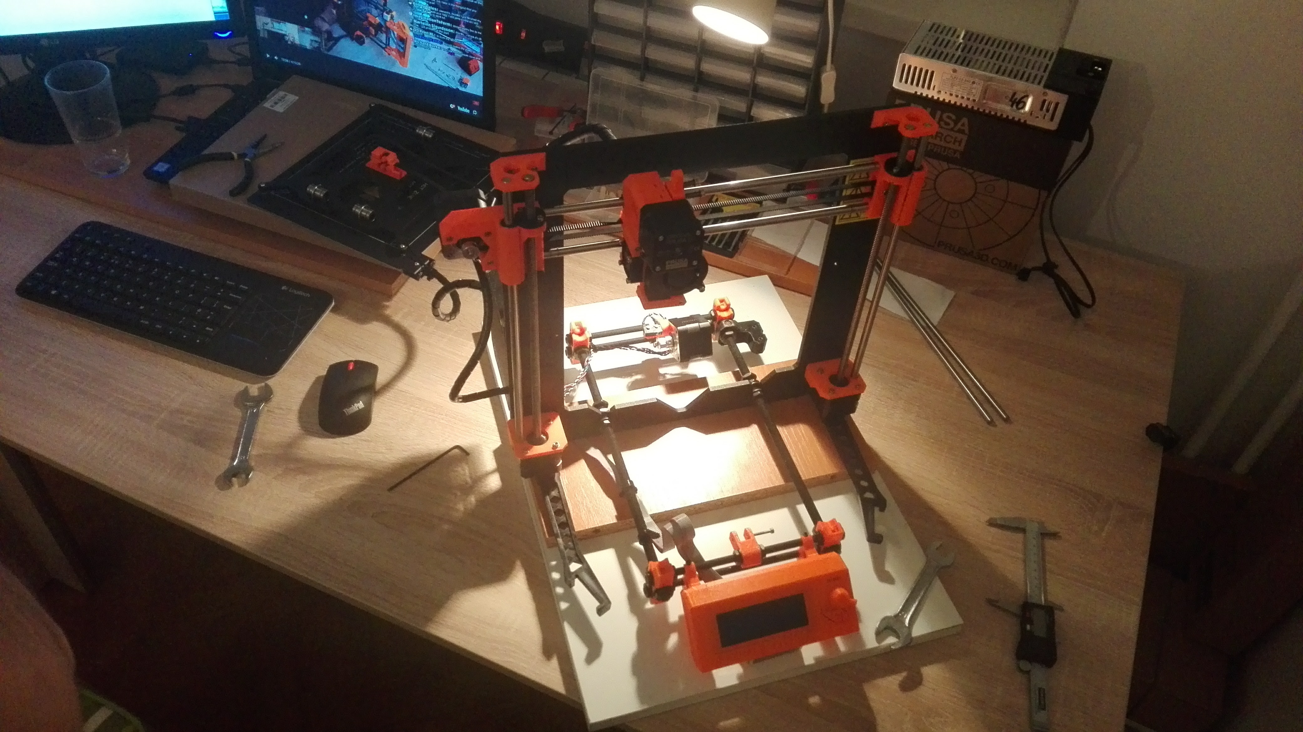
Ok, here are some pics:
Re: I need assistance in making my kit square
And some more:
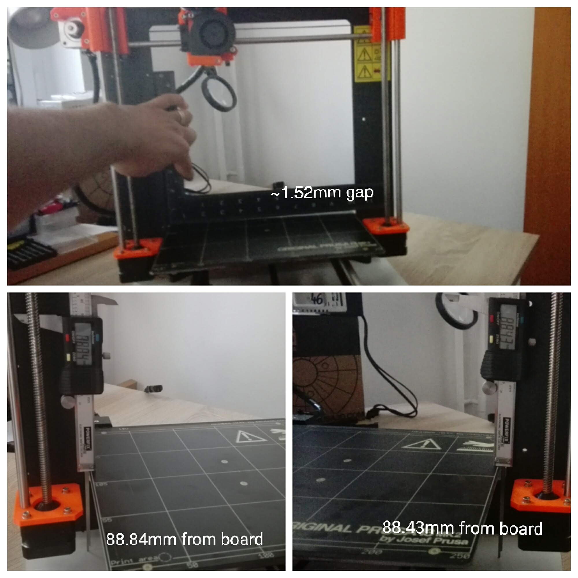
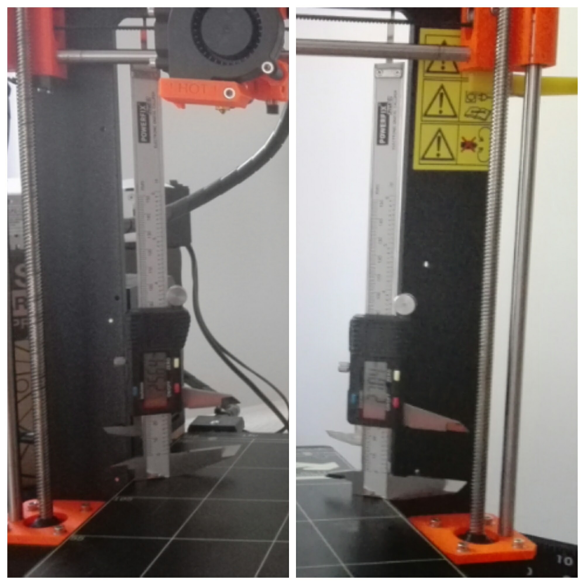
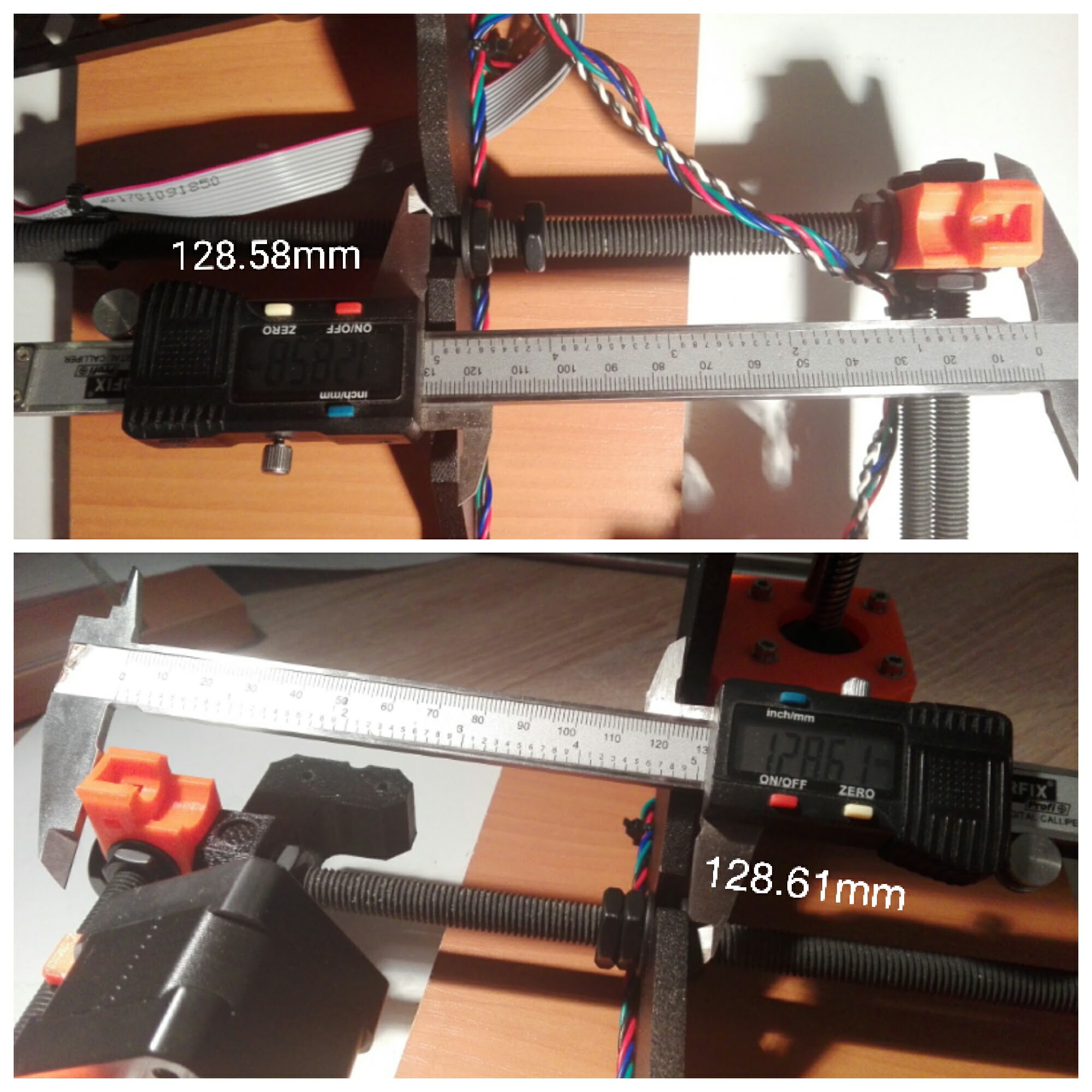
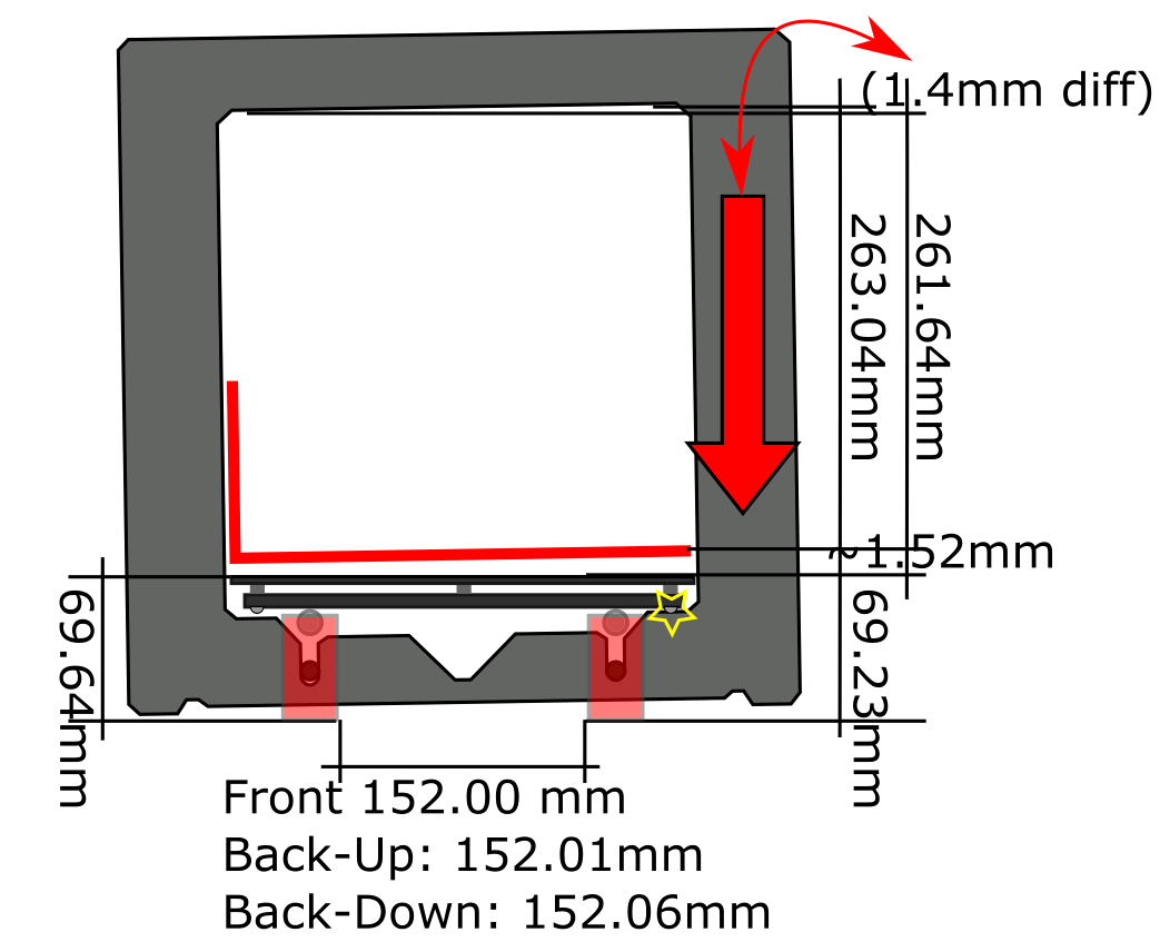
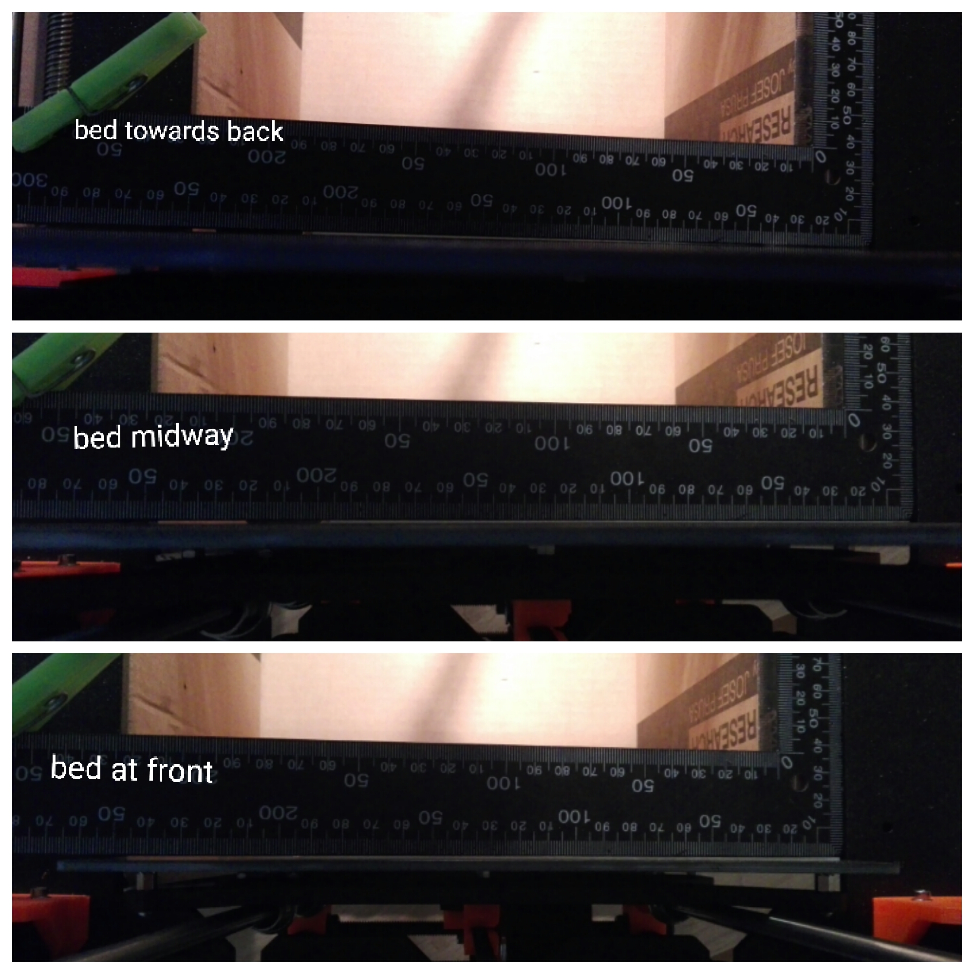
1.4mm difference .... quite in line with the 1.52 I measured at the gap between ruler and bed on the right side but quite a huge number in terms of what tolerances the build needs to ensure a good service with dimensionally correct prints.
Re: I need assistance in making my kit square
Some more numbers:
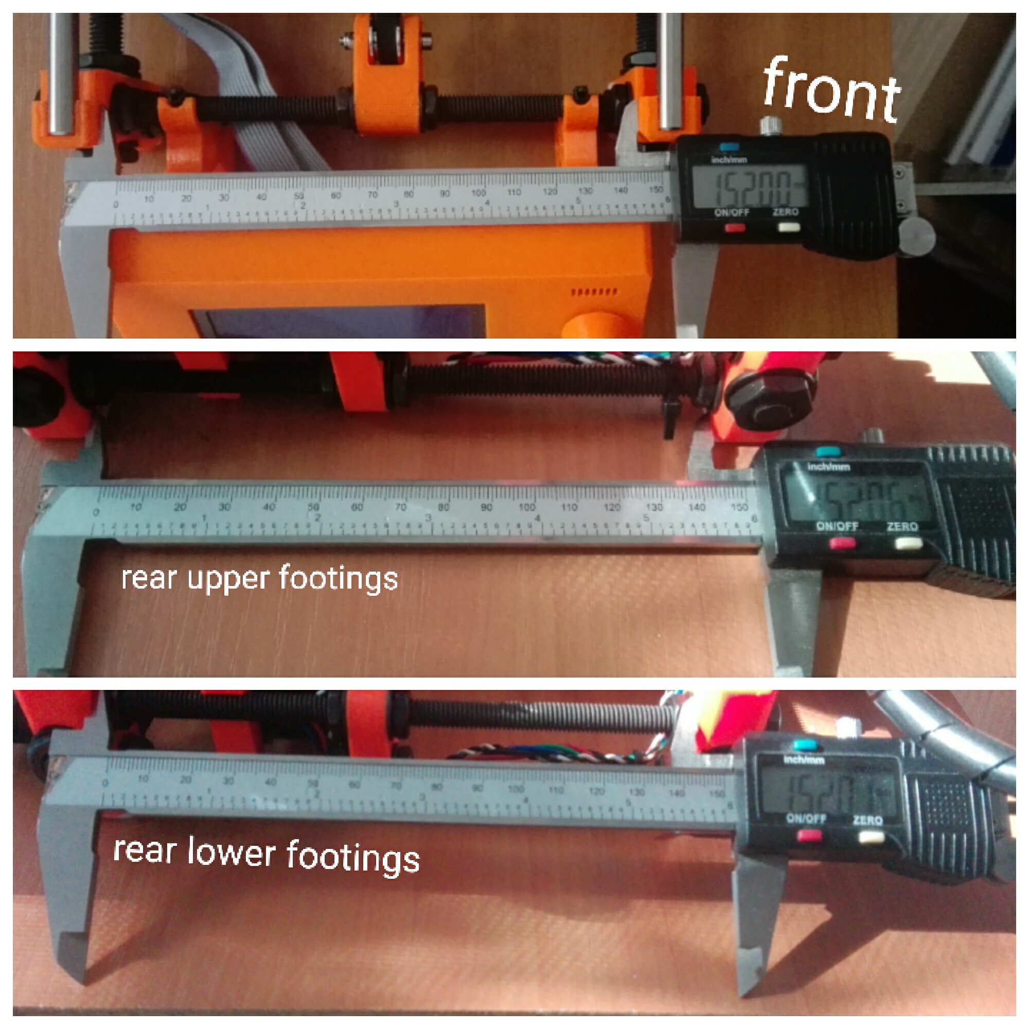
* got the labels in the wrong order though ... middle picture is the lower side of the plastic feet and bottom is the measurement between the iupper side of the plastic feet 🙂 ... you get it.
Re: I need assistance in making my kit square
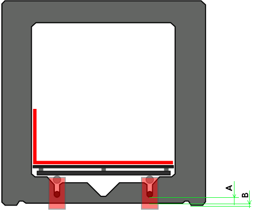
Could you take measurements as explained by picture with letters A and B respectivly on both left and right sides?
There is a possibility that the frame itself has some defects - so just to be sure...
/Henrik
Re: I need assistance in making my kit square
Also - could you measure the heat bed on several locations with e.g a steel ruler and a leaf measure, as depicted by arrows, and try to compare the various spots on the bed somehow.?
The heat bed in itself have manufacturing tolerances and maybe is not so flat as one might expect.
/Henrik
Re: I need assistance in making my kit square
I was initially confused by all the other images of measurements since they have little to do with roll alignment. As you probably know, the only definer roll alignment are those two dips in the frame. If all fails perhaps you could adjust the Z-Motor mount and Z-end stop position slightly up or down slightly. Firmware won't care if frame looks askew as long as X-gantry is aligned to bed surface. But I do hope you find the issue.
MK2S kit owner since 8/15/2017
Re: I need assistance in making my kit square
I wouldn't take it apart to that point where I can measure the notches in the ZPlate :-s ... not yet that is.
Here is what I gathered so far:
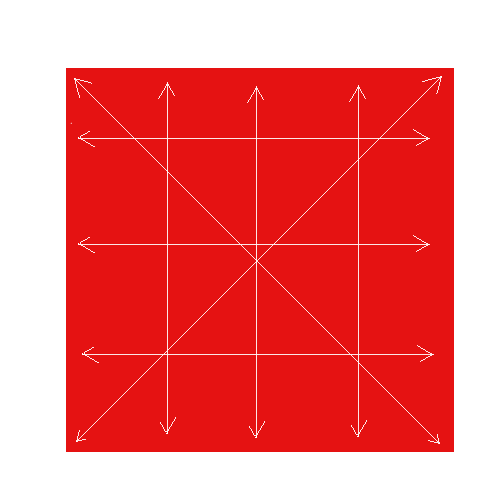
Because basically I have to make Z, which goes together with X, perpendicular to the bed all I care is getting the ZPlate rotated so that it's square with the bed. For this I can slightly un-fasten the nuts on the YRod where it touches the ZPLate (yellow star on sketch) and tap it down while taking measures until I get where I need to be...
Re: I need assistance in making my kit square
Maybe you could use aluminum foil shims. Stack until desired offset and cut to fit in the dip? Then you could just focus on putting enough pressure on the threaded rod so it doesn't creep up as you tighten. The captured shim could also make yaw alignment easier as roll adjustment is semi-permanent. I found ensuring roll and yaw aligned at the same time cumbersome with a square kit, it could be even more difficult with your situation.
MK2S kit owner since 8/15/2017
Re: I need assistance in making my kit square
I have no idea how to plot a 3d heatmap of the numbers so one can see where I am but in Excel it looks like this:
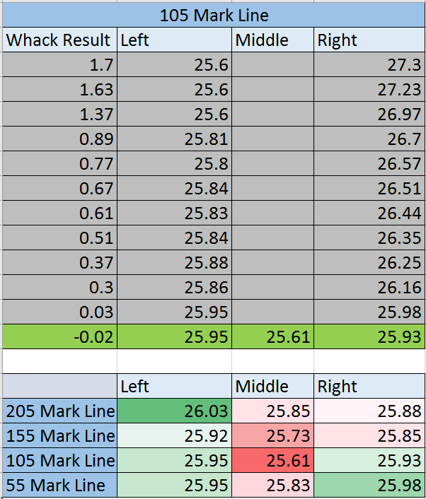
I have loosened a bit the right single-side nut on the YRod and tapped the ZPlate on the upper corner until I had a minimum difference between left and right. The measurements were taken with the upside down caliper using the tail so the numbers actually mean the difference in tail length exiting the caliper body. The difference between them is important anyway so judge by that 🙂 .
I still see a bow (concave) in the middle, I might have fastened pretty hard the middle bolts because before I had a convex bow.
How do you feel about these numbers?
Re: I need assistance in making my kit square
Ok, managed to get to the values below pretty straight-fw but noticed straight to the eye that the Y gantry is skewed and I can't yet get it why (as long as the back feet to ZPlate is 100mm +- 0.1mm tops). It's like I need the ZPlate to be a couple mm more on one side...
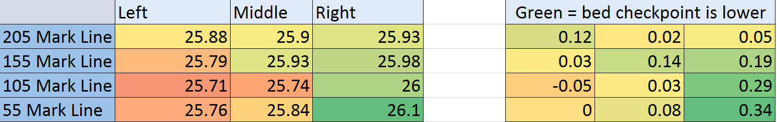
You can see the square (also black) across the bed and the white line at 155 Mark almost dissapearing under the ruler on the left side while on the right it's 2-2.5mm away from the ruler... why could that be (there is an almost spot-on 152mm between the interior faces of the plastic footings, as the manual ask)
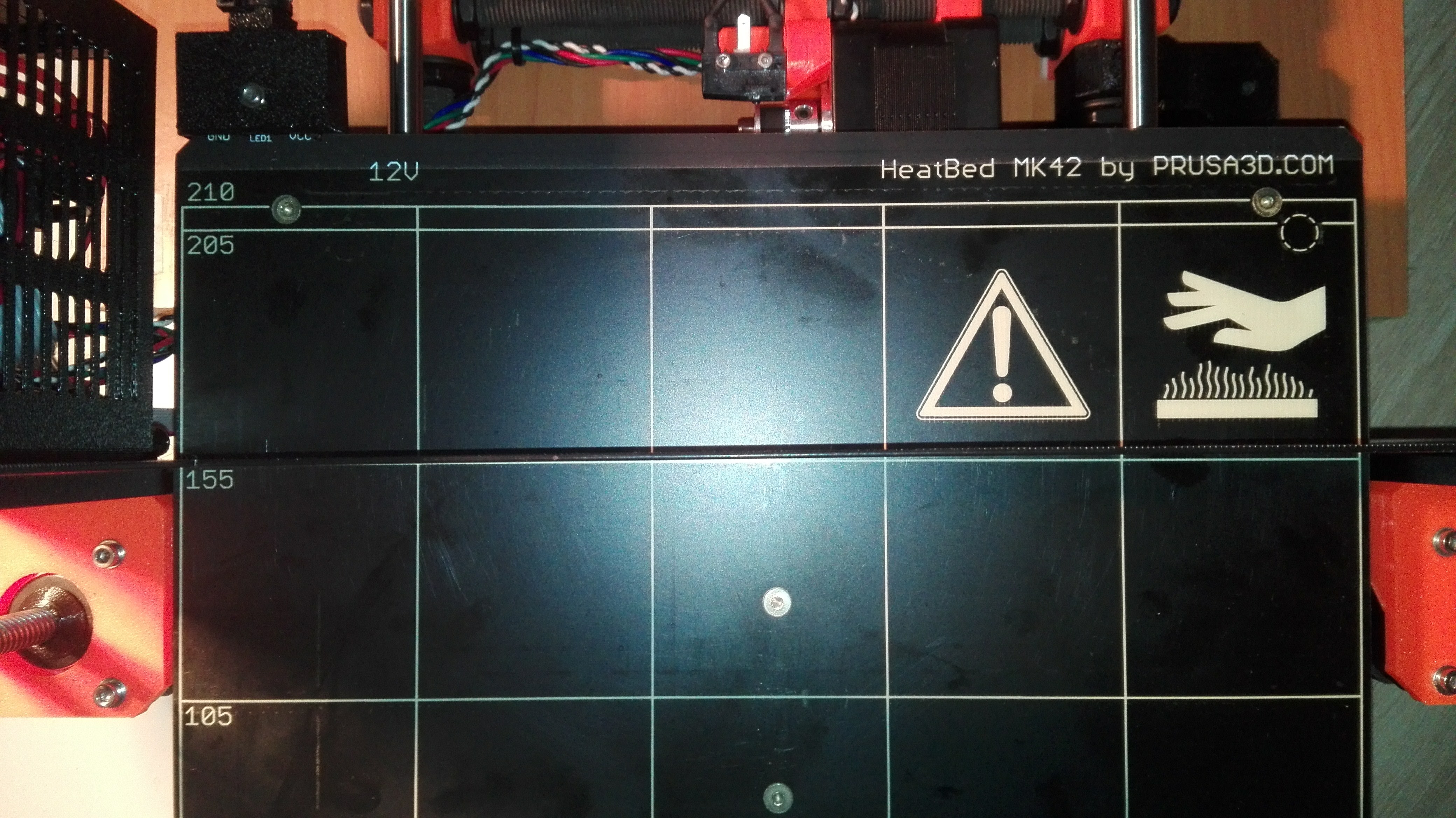
Why would this be? :-/
Re: I need assistance in making my kit square
The values that you have accomplished to adjust the bed to seems to me as very good ones. The firmware will probably have no problem to adjust accordingly. My machine is an old one from 2015 and it uses a glass bed - that in itself is warped badly (0.1 - 0.3 mm difference , corner to middle) when approaching the corners - but very flat (in the few +-0.001 mm perhaps) on a square approximately 120 x 120 mm in the middle.
*I think that the frame you have may be warped when looking from the top Z. When I used a steel ruler (made in Japan - confirmed to be very flat and straight) and measured the frame from side to side and had a gap approximately 1 mm will I remember - from the edge to middle part). This did however not too much with the precision a the z-axis slide on the rods and not on the frame itself, so I did not need to replace the frame.
/Henrik
Re: I need assistance in making my kit square
These teething problems seem to never end 🙁 . Not sure you guys can have much to chime in with but nevertheless I will post for a way to look back or others that might encounter these issues.
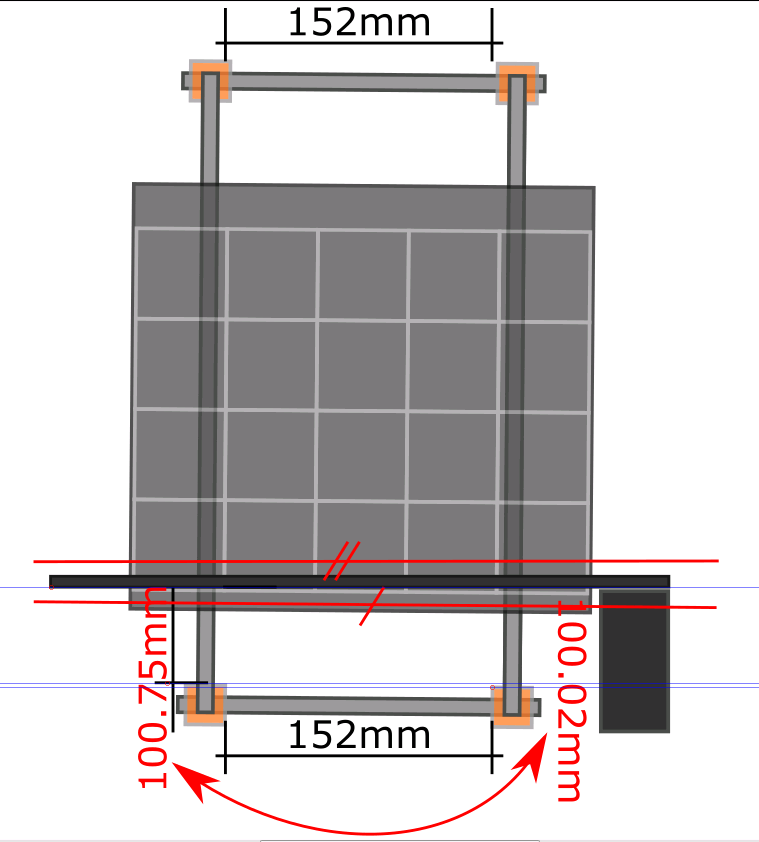
Latest surprise... check this out : the skew is like in the attached picture (bed rotated away from the electronics box) which would suggest that the distance from plastic foot to the ZPlate is bigger on that side and smaller on the opposite side right? Not. My measurements show the distances the other way around (albeit by a very small margin ... like 0.2mm or so) and right now I can't figure out how can it be skewed if those distances are almost spot-on 100mm... :-/ 🙁
Any ideas?
Re: I need assistance in making my kit square
I'm just getting through my kit build and working on dialing in my first few prints. I'm getting decent results, but I think I must have some sort of unevenness in the bed because I'm consistently getting a raised edge in one area of my prints (as if it's lower and the plastic isn't adhering well because the bed is moving away from the nozzle in a small spot). I'll get a better picture of how the print looks tonight, but here's where I'm seeing my issue:
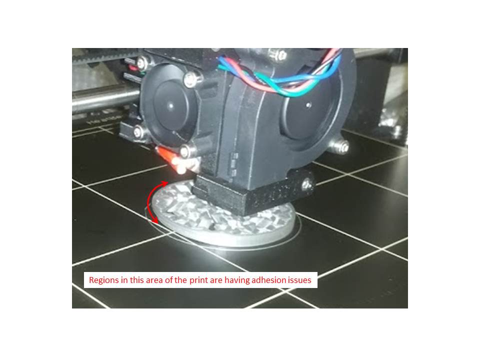
I don't have all of the measurement data that you do yet, but I can confirm that I have a similar type of twisting situation between the bed and the Z frame. When I try and visually align my X rods with the lines on the heatbed, I have to put quite a bit of offset into one side of the threaded rods/Z frame junction.
Just as you show in your picture... If I set an even 100 mm from the back feet to the Z frame on both sides, then the rods are very unparallel from the lines. I've managed to get through the calibration procedure with a fixable amount of skew though; the book says that the software will adjust appropriately for the skew, but that I might still want to look for misalignment.
I may just roll with it as-is though, if I can solve the adhesion issues in that spot of the bed, either through calibration or shimming.
I don't know yet what is causing the twisting in the Y carriage though. I'll be inspecting it all with calipers tonight to see if I can find the culprit. Either the rods are sitting crooked in the printed parts, or maybe the linear bearings are somehow off. I'll post back with some results later to see if I can figure it out.
Re: I need assistance in making my kit square
@florin - did you see my comment above yours about a frame that may be warped?
/Henrik
Re: I need assistance in making my kit square
Hi Henrik,
Yes I did and there was no way to answer that but to take the everything apart and to test the frame against some flat-ish surfaces .... I tried the following: double glazing window , wall mirror and my desk but easiest was to film it on the desk. It looks slightly warped but dunno about the effects of that quite small warp on the calibration or prints: https://photos.app.goo.gl/7vqFUq5j5qr4g3oX2
I am putting the printer together and keep an eye on all dimensions and check it with the caliper and the square and I am mostly put off by the Y assembly twist (where the two smooth rods are rotated in the X axis so each rod has a lower end and a higher end). If the Ycarriage is twisted then no amount of calibration can solve that because say you make front of the bed parallel with XRods, then you move the bed to a middle point where the Ycarriage twist will place the bed at a different angle than the front of the bed so you can't adjust that position without loosing the front calibration. There is where the 9 point calibration should solve the issue but I am a firm believer in a sound hardware assembly and software compensation only as a last resolrt, something I don't believe I can achieve with Prusa 🙁
To show you what I am talking about:
Re: I need assistance in making my kit square
Florin, it might be time to just accept the unit's flaws and get a new bed under warranty. That bed is way skewed compared with others on this forum I've seen including mine which I am thankful is near perfect from factory. Perhaps if you can deal with loss of heat performance and z print area you can swap the PEI with a thin glass plate with that 3M thermal adhesive? You can even put a PEI on top of it too if you like. So much effort, you deserve a win.
MK2S kit owner since 8/15/2017
Re: I need assistance in making my kit square
Good - the warp that you showed with the frame on the desk seems to me to be of little impact. It is small and comparable with the frame of mine and I don't think it will show up in the quality of the prints.
On the other side - the bed as you show in the picures with a square and light fabric the background, showing a slanted bed, could depend on the small inserts (marked by whiter squares in the picture) on the backside of the bed.
Are the inserts fully inserted in the bed on all the spots?
/Henrik
Re: I need assistance in making my kit square
Forgot the picture 🙂 :
