Re: Z Axis Brace
Hot damn, you just found a huge contributing factor to that vertical line issue. 🙂
I wonder what would happen if we re-positioned the rubber feet closer to the center? Also, any chance I could grab that hard feet STL? May want to do some modification and see about sticking felt on the bottom of them.
Thanks!
Just a note from experience, felt is very slippery. It is usually used to protect one object from scratching another but it slides easily across a surface. The bump pads referenced do not slip, they 'grab' which I believe is the desired result. Google " clear rubber bumper pads " and you should find them.
The MK2 used felt feet. I print on a paver stone and those felt feet gripped awesome and had very little give while damping vibrations. I liked it better than current solution and was thinking of changing back. Given this thread I think I will.
Re: Z Axis Brace
The MK2 used felt feet. I print on a paver stone and those felt feet gripped awesome and had very little give while damping vibrations. I liked it better than current solution and was thinking of changing back. Given this thread I think I will.
Agreed. Paver stones are designed to walk on without slipping so they are an excellent substrate. I just keep reading posts about printers on top of 'solid' or 'sturdy' wood desks and cabinets and the like. Felt in that environment was my concern.
Maybe someone could attach a seismometer to their MK and do a series of tests of different 'feet' on different surfaces. :geek:
- MK3s w/Mosquito Hotend- Mini w/Copperhead Hotend- XL - 5 tool -OpenScad -3d Builder -FreeCAD -Alibre -OctoPrint/x3(Pi3B)
Re: Z Axis Brace
Not sure how the sorbothane will work (will find out tomorrow), but I designed some feet that can handle both sorbothane hemispheres OR felt pads: https://www.thingiverse.com/thing:2802540
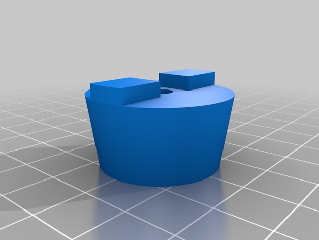
Printing the other 5 I will need now, should have sorbothane in tomorrow and will give it a test. Figured some felt bros here might want to give this a shot too. Need an M5x16 and a 3030 M5 t-nut per foot.
My MK3 Parts: [Bowden] [New Shoes] [TPU Micro Springs]
Re: Z Axis Brace
Printed these out tonight, but they are too tall. With these on and the front feet touching, my back feet are in the air by 1mm'ish. With the revelations David has found in this topic and the percentages of people having the issue vs not, I am starting to think Prusa may have pulled another fast one and sent some of us different feet than others. I have a big print going at the moment, will get a pic of the rubber feet I have once it completes.
Which TPU did you print them out with? 85A or 95A?
Re: Z Axis Brace
Not sure how the sorbothane will work (will find out tomorrow), but I designed some feet that can handle both sorbothane hemispheres OR felt pads: https://www.thingiverse.com/thing:2802540
5a42fb36243f79258382fd4afe1e9e91_preview_featured.jpg
Printing the other 5 I will need now, should have sorbothane in tomorrow and will give it a test. Figured some felt bros here might want to give this a shot too. Need an M5x16 and a 3030 M5 t-nut per foot.
Love it. I did a similar riff on my first piece. It's uhhhhhh... 2 pieces... takes the same vinyl bumper..
Re: Z Axis Brace
Sorbothane is in and installed. Went six feet as planned (around 2.4lb per foot, they are rated 2lb to 4lb as the sweet spot). Looks pretty swag. 🙂
I have an XYZ cube going right now at the default 40mm/s @ 600mm/s accel, which I have some pics of from my first testing days before I dropped to 15mm/s or 100mm/s accel for everything. Will post comparisons when the cube completes, but man I can't wait. So far:
My MK3 Parts: [Bowden] [New Shoes] [TPU Micro Springs]
Re: Z Axis Brace
For reference, here's the previous 40mm/s @ 600mm/s accel cube that I tested:
Here's one with the same settings but sorbothane feet:
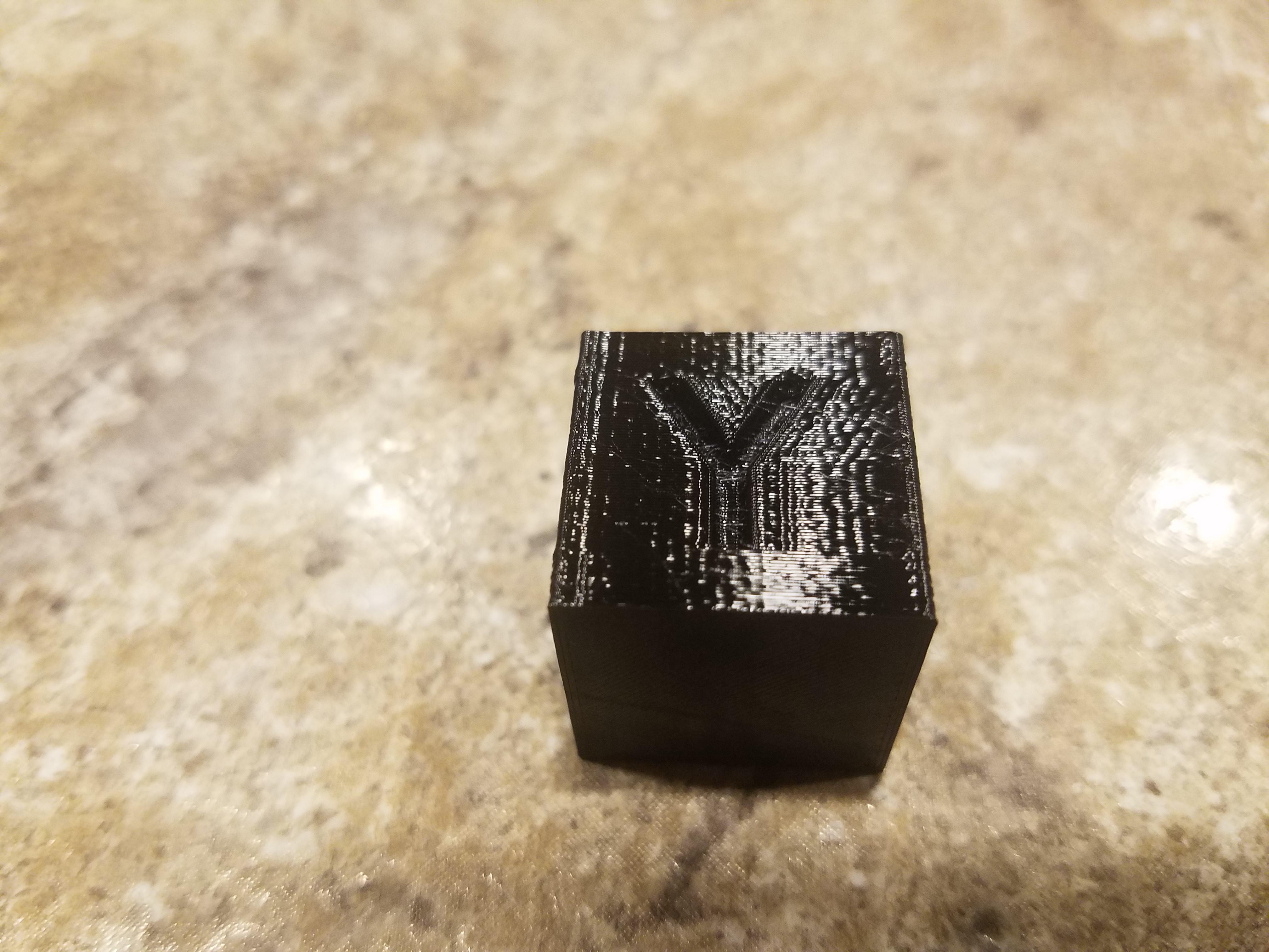
Still some ringing that I suspect is acceleration related, going to get another cube going at the lower 100mm/s accel and see how the ringing goes; however, you can definitely see less artifacts above/below the Y. Will post the lower accel version in a few.
My MK3 Parts: [Bowden] [New Shoes] [TPU Micro Springs]
Re: Z Axis Brace
For reference, here's the previous 40mm/s @ 600mm/s accel cube that I tested:
Here's one with the same settings but sorbothane feet:
2EjrGqy.jpg
Still some ringing that I suspect is acceleration related, going to get another cube going at the lower 100mm/s accel and see how the ringing goes; however, you can definitely see less artifacts above/below the Y. Will post the lower accel version in a few.
Wow. looks like a nice improvement. Damping out the ringing in the structure. We'll find the source and end it I'm sure.. Edit... Dammit, i quoted the wrong post. You know I meant the Sorbothane one... Doh!.
Re: Z Axis Brace
I have a MK3 on order, my 1st 3d printer. So, I may have it all wrong. OK, here goes..
I plan to put my printer in an enclosure & mount the electronics & power supply outside the enclosure. So, I have been pretty interested in ways to stiffen up the printer. My current plan is to add 2, 30x90 extrusions to the back side of the frame, just outside the existing 30x30 back extrusions. These will run the full height of the frame(370mm) & be cross braced on the top at the rear with a 274mm 30x30 extrusion. Should look sort of like this:
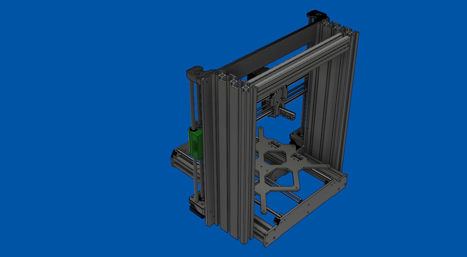
So, what do you think? Is this crazy?
(I really like the sorbothane feet, btw)
Re: Z Axis Brace
bhawkeye,
as the MK3 is not a rock solid design and you write this is your first 3d printer, I'd recommend you leave it unmodified for starters. You'll encounter enough problems without modifying it from the beginning.
Regarding your modification - what do you intend to achieve by that? It massively increases the stiffness of the frame in Y direction, but I am not convinced that this is a problem at all, because the Y carriage is separated from the Y/Z drive. Best investment to start with (as described in another thread) is a paver (just got a 40x40 cm concrete plate for my MK3).
I have some experience in modal analysis and debugging vibration problems on precision machinery. But looking at my MK3, I have to admit I don't see any obvious single point weaknesses. My first guess would be belts (too low stiffness) and linear bearing cogging, which together could cause ripples in the surface. But the MK2S also had those and worked much better (comparing my MK2S and MK3 benchies). Next guess would be the Y and X axes, the rods being rather long and prone to bending.
Anyway, to remove the guesswork, a more detailed analysis would help. What I found great tools in industry work are high speed cameras (nowadays some consumer cameras and smartphones have this ability) and measuring of the toolpath with a PSD ( https://www.hamamatsu.com/us/en/product/category/3100/4010/4156/index.html ). Put a light source (LED, laser) on the tool (nozzle) and a PSD on the print bed. This, together with some vibration measurements on the structure, could help pinpoint the weak spots.
- Martin
- Martin
Re: Z Axis Brace
Thanks for the good advice Martin. I'll follow your advice(although I did order Misumi rods & bearings, which I plan to do the initial build with).
I'm dying to see what Brigandier's next results were.
Re: Z Axis Brace
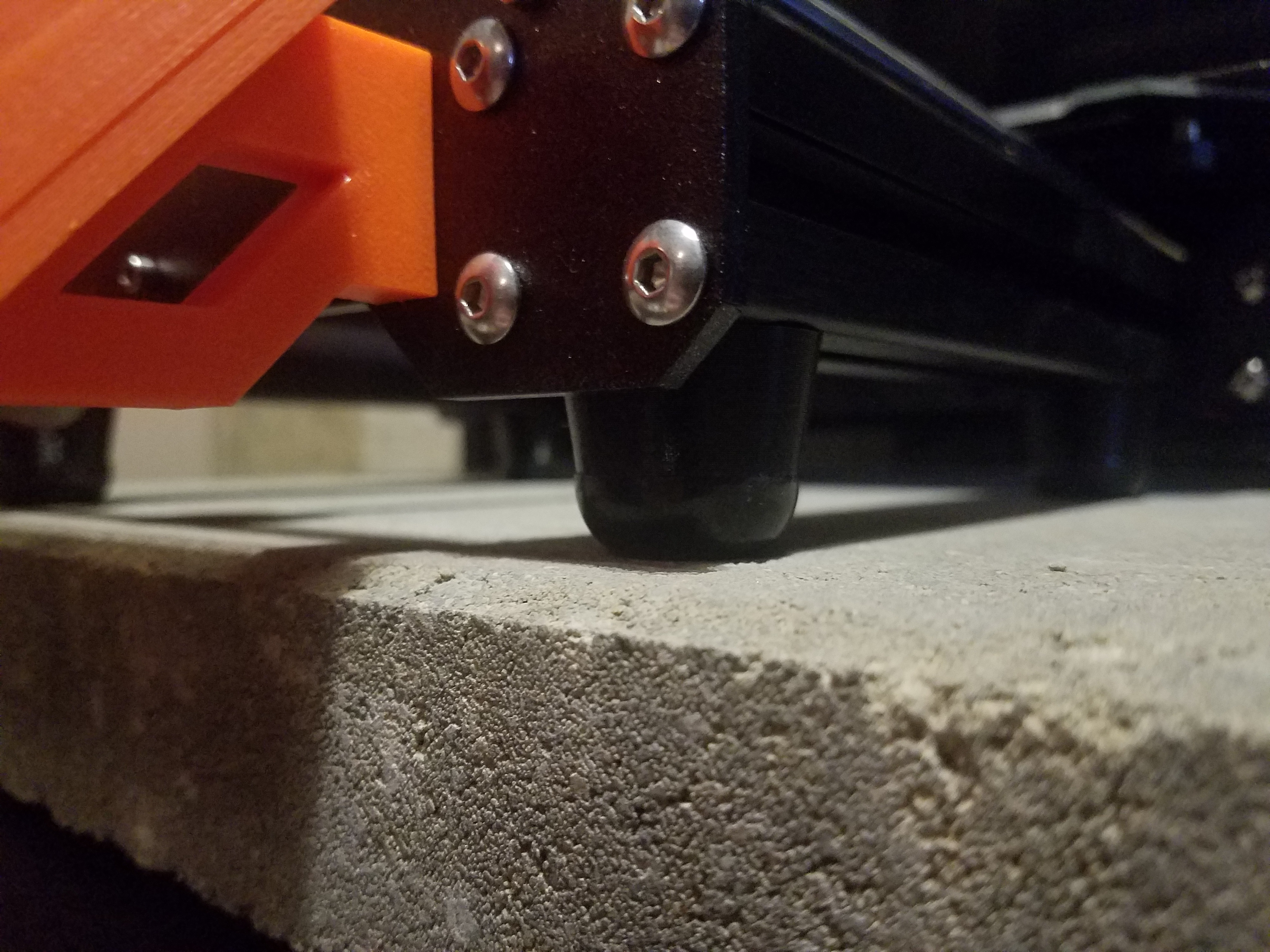
Did a similar upgrade today, 8 pack of 1" sorbothane feet from Amazon, 3 evenly spaced on the front extrusion, 1 on the rear, and it really is the weirdest thing setting it down or picking it up now, like boot stuck in mud.
I've got a paver underneath the printer, a 2x4 framed workbench with a half sheet of 3/4 ply screwed down to it as a work surface, a 2nd 2x4 framed tier underneath with a 1/4 mild steel plate as the surface to add weight (had it sitting around). Even with that heavy setup the table was jerking around enough that the architectural arm light (whatever they are called) mounted to it visibly swayed. After the sorbothane I can still see the light move a little but its not obvious and it feels much better if you're touching it while running.
Re: Z Axis Brace
Did a similar upgrade today, 8 pack of 1" sorbothane feet from Amazon, 3 evenly spaced on the front extrusion, 1 on the rear, and it really is the weirdest thing setting it down or picking it up now, like boot stuck in mud.
I've got a paver underneath the printer, a 2x4 framed workbench with a half sheet of 3/4 ply screwed down to it as a work surface, a 2nd 2x4 framed tier underneath with a 1/4 mild steel plate as the surface to add weight (had it sitting around). Even with that heavy setup the table was jerking around enough that the architectural arm light (whatever they are called) mounted to it visibly swayed. After the sorbothane I can still see the light move a little but its not obvious and it feels much better if you're touching it while running.
Awesome. When you say 3 on the front, 1 on the rear, do you mean on each side for 8 total? I am curious about going this route as well or sticking another under the PSU. I am seeing noticeably more squish on the pad that's under the PSU, not sure if it's affecting operation or not. I didn't consider that the weight isn't evenly distributed on the printer.
How much quieter was your machine after installation? 🙂
My MK3 Parts: [Bowden] [New Shoes] [TPU Micro Springs]
Re: Z Axis Brace
Awesome. When you say 3 on the front, 1 on the rear, do you mean on each side for 8 total?
4 on each side so used up all 8, just took off the rubber stock feet and stuck them on. Judging from just the squish of each I think you could get away with just 3 per side if you're using 1" ones. The front most one doesn't really deform at all.
Honestly it was so quiet anyway before adding them its hard to notice the difference in sound, but on rapid infill especially in smaller areas where the x is whipping around like crazy it seems to make a difference. Vibration is much improved though, wondering if just another paver or a sheet of something damping under the current one will take care of whats left.
Re: Z Axis Brace
wondering if just another paver or a sheet of something damping under the current one will take care of whats left.
Just got my MK3 and bought a 40x40 cm paver and put a bike tube below it. Perfect sound insulation. See my earlier post here:
https://shop.prusa3d.com/forum/improvements-f14/best-usd7-buck-improvement-you-can-make-t3051-s20.html
Have not yet checked if print quality improved, did it for quieting the printer. I set it on stealth, 100 mm/s travel max, near inaudible. Nozzle fan is the loudest part now.
- Martin
- Martin
Re: Z Axis Brace
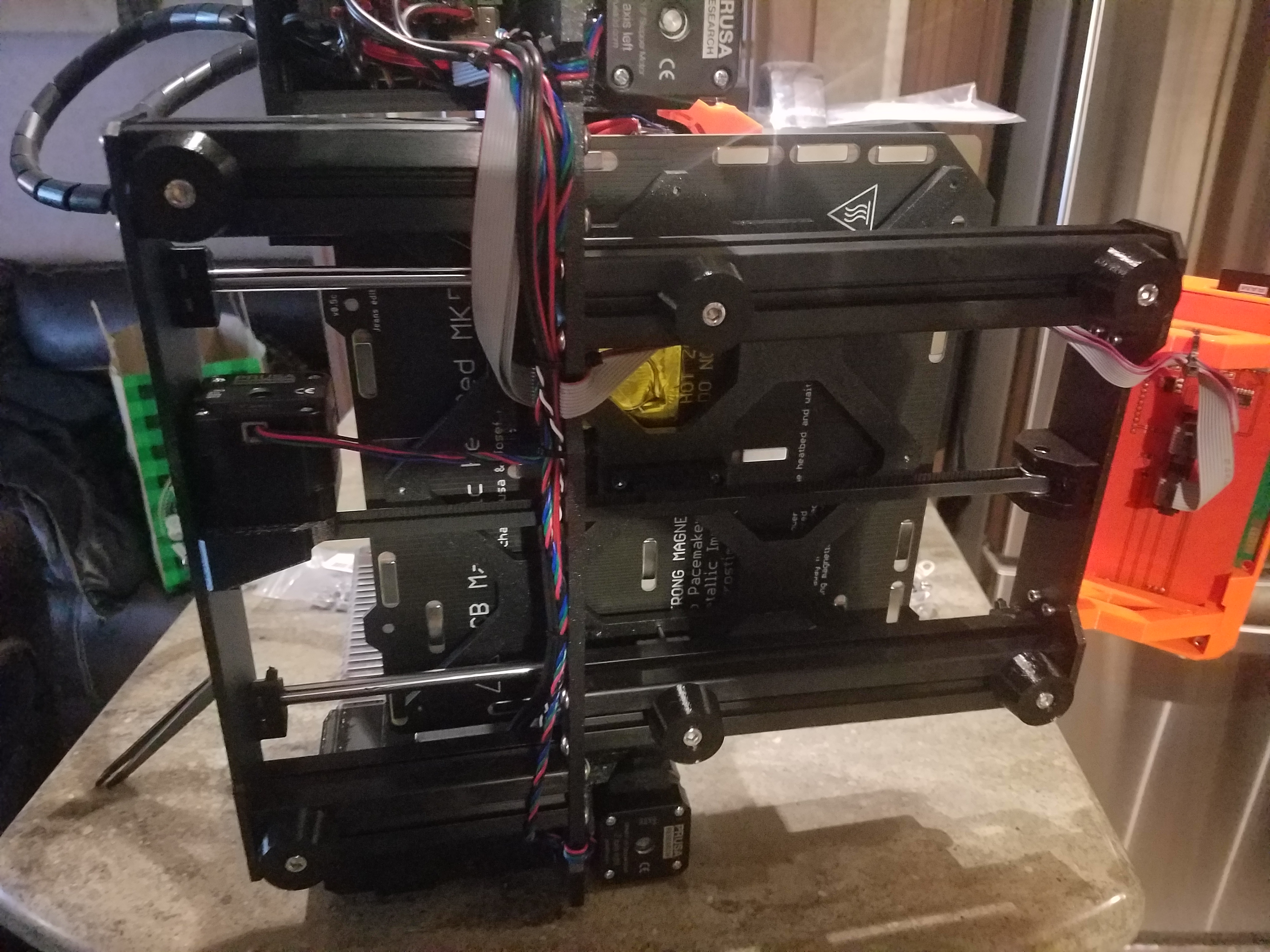
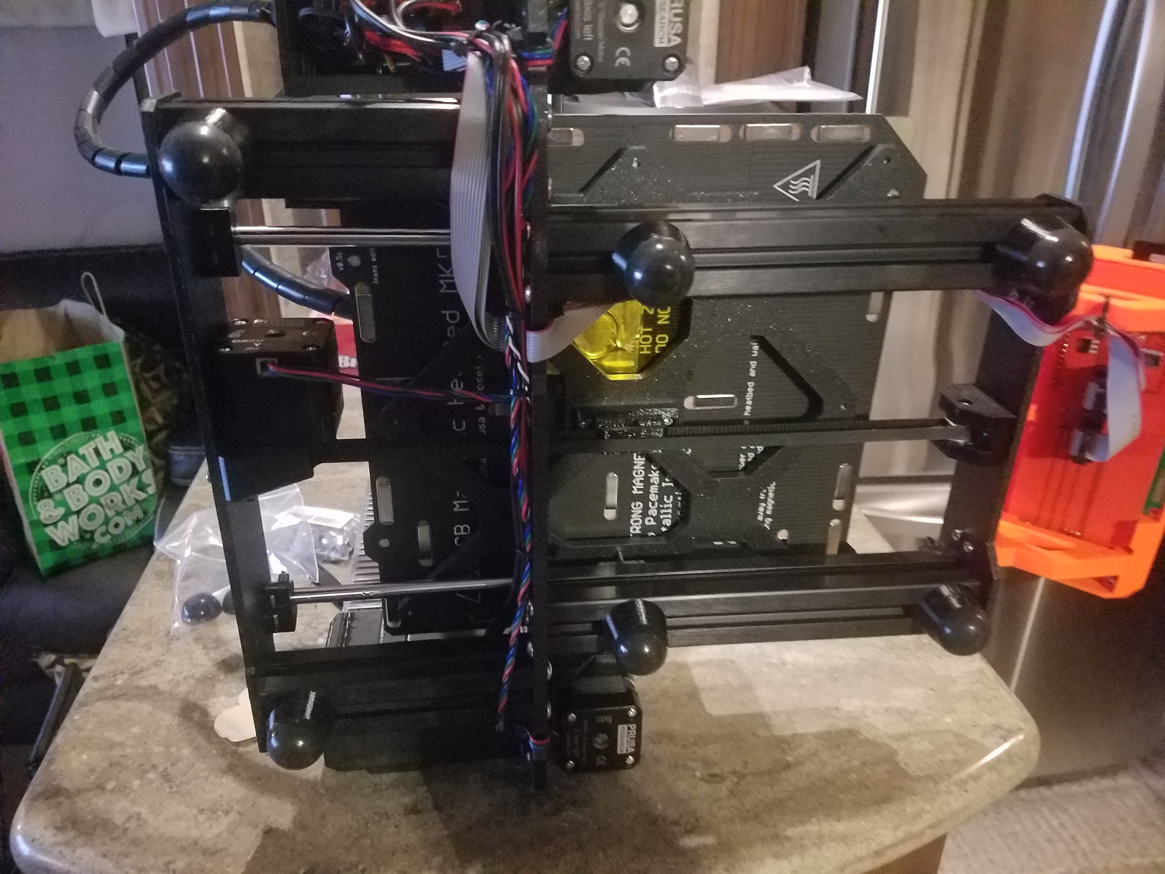
I made these new feet and the printer is much more stable, just from pushing it around by hand. I will see if I can turn up acceleration.
Re: Z Axis Brace
I made these new feet and the printer is much more stable, just from pushing it around by hand. I will see if I can turn up acceleration.
https://www.thingiverse.com/thing:2805753
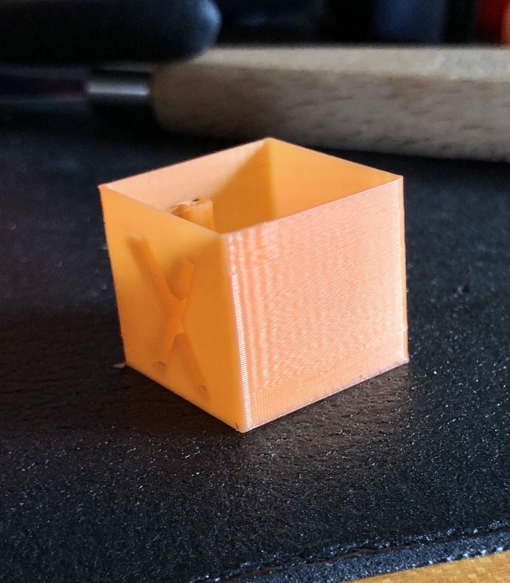
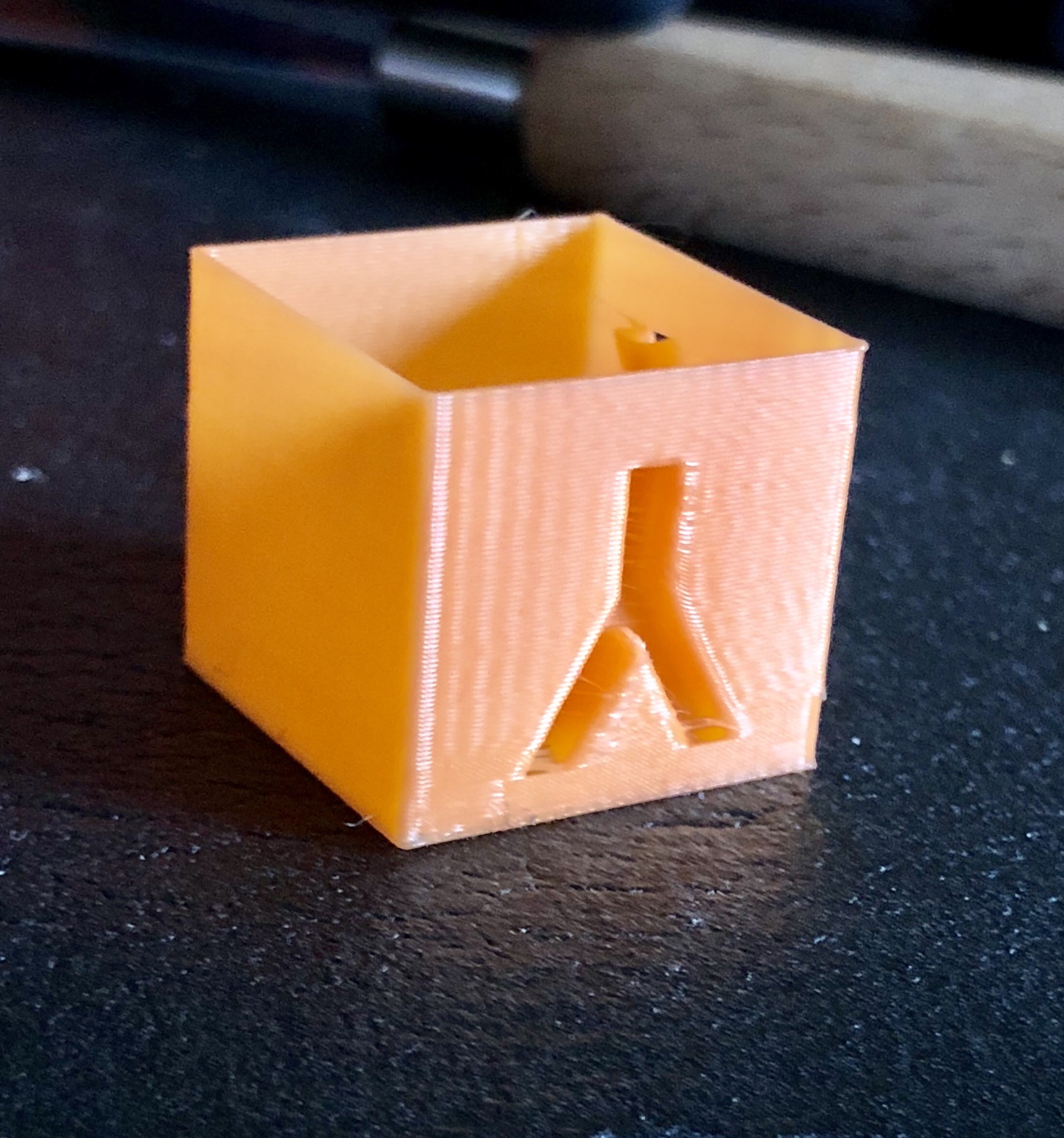
I printed a single wall cube. I couldn’t get slic3r to go any faster than 15mm/s for some reason. So I waited for the first 5mm then cranked it to 400%.
I adjusted photo lighting to exaggerate the ripples. It is not so extreme in reality.
The X is pretty smooth.
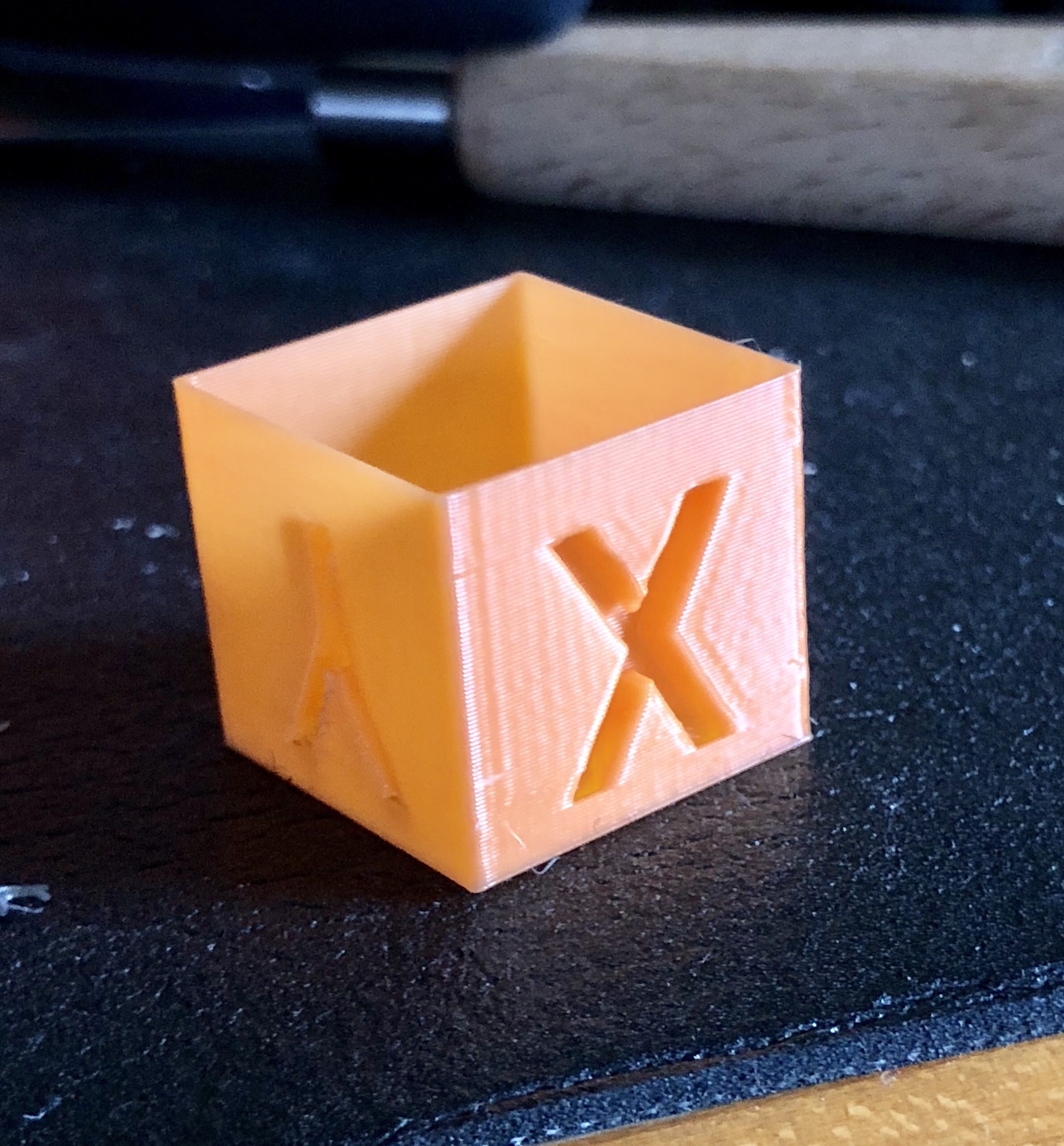
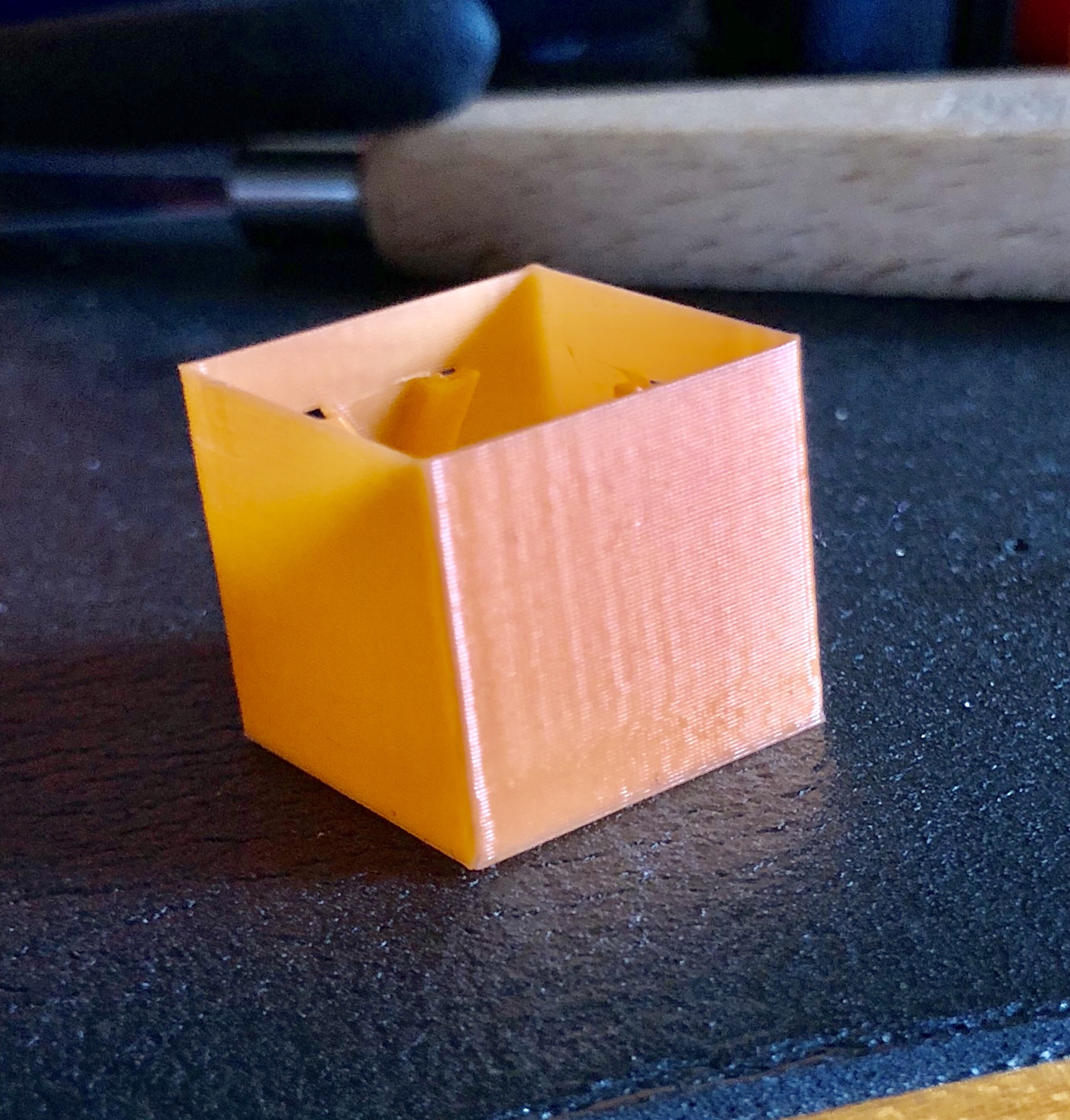
The Y is still worst but much better than before. Notice how smooth the first 5mm is at the slower speed.
Re: Z Axis Brace
Re: Z Axis Brace
I made these new feet and the printer is much more stable, just from pushing it around by hand. I will see if I can turn up acceleration.
https://www.thingiverse.com/thing:2805753
I printed a single wall cube. I couldn’t get slic3r to go any faster than 15mm/s for some reason. So I waited for the first 5mm then cranked it to 400%.
I adjusted photo lighting to exaggerate the ripples. It is not so extreme in reality.
The X is pretty smooth.
38E1040A-FAE7-4DA6-878F-634DDE7D0ADB.jpeg
DEC29534-45FC-4DCD-B1B1-75A060F6F5A3.jpeg
The Y is still worst but much better than before. Notice how smooth the first 5mm is at the slower speed.
BE816A2C-0C47-466D-8FBF-8C68F1821737.jpeg
Similar results to what I am getting. I suspect your speed is being throttled due to layer time in seconds. Try something like 30mm/s with 100mm/s accel on external perimeters. It's a bit of a toss up, but I just print at 15mm/s externals now.
On your first 5mm of 15mm/s, do you see the scratch like vertical lines? It doesn't matter how slow you go, they are there. I am trying to figure out if this is movement related, or maybe direct drive extruder resolution not being high enough? I have the Flex3drive adapter coming which will turn mine from 1:1 to 40:1, hopefully get rid of that artifact.
My MK3 Parts: [Bowden] [New Shoes] [TPU Micro Springs]
Re: Z Axis Brace
I made these new feet and the printer is much more stable, just from pushing it around by hand. I will see if I can turn up acceleration.
https://www.thingiverse.com/thing:2805753
I printed a single wall cube. I couldn’t get slic3r to go any faster than 15mm/s for some reason. So I waited for the first 5mm then cranked it to 400%.
I adjusted photo lighting to exaggerate the ripples. It is not so extreme in reality.
The X is pretty smooth.
38E1040A-FAE7-4DA6-878F-634DDE7D0ADB.jpeg
DEC29534-45FC-4DCD-B1B1-75A060F6F5A3.jpeg
The Y is still worst but much better than before. Notice how smooth the first 5mm is at the slower speed.
BE816A2C-0C47-466D-8FBF-8C68F1821737.jpeg
Similar results to what I am getting. I suspect your speed is being throttled due to layer time in seconds. Try something like 30mm/s with 100mm/s accel on external perimeters. It's a bit of a toss up, but I just print at 15mm/s externals now.
On your first 5mm of 15mm/s, do you see the scratch like vertical lines? It doesn't matter how slow you go, they are there. I am trying to figure out if this is movement related, or maybe direct drive extruder resolution not being high enough? I have the Flex3drive adapter coming which will turn mine from 1:1 to 40:1, hopefully get rid of that artifact.
I read somewhere that the hobbed gears can cause that by creating micro-pressure fluctuations in the chamber. The Bondtech will make that twice as bad. Not sure I believe it. But I could live with that if I the ringing would go away.