Re: Z Axis Brace
Looks to me like the printer rests on the rubber feet, if installed, or the front & rear plates - if the feet are not installed. The extrusions don't appear to touch. But, one thing that seems obvious is that when the bed is all the way forward it is much further away from the Z axis than when it is all the way toward the back. Perhaps this factors in.
Don't have my printer yet - so just trying to learn from you guys.
Re: Z Axis Brace
You know, I've been baking on this one for a bit...
The middle of the printer isn't actually touching "ground". The entire thing is being held up by the four corners of the extrusions.
I wonder if that might be a bit much to expect the bolts to secure on their own.
So I've been thinking of running an experiment like supporting the center frame on some springs to help with the load of, you know, the entire printer right in the middle.
Out of town at the moment so can't look directly, but from this image:

It looks to me like the Z frame is a bit lower than the extrusions coming off of it, and the front/back plate definitely are. I wonder if you could print some rigid feet, say 8, to support front/back and front/back of center? Maybe with a nice circular area to hold felt and go directly against a paver? I have read the antivibration feet lower the noise, but also increase amplitude of what vibration does happen (like bad shocks on a car). Seems to me felt would keep it quiet/safely in place, and along with the extra feet, give more support than the squishy rubber?
Sorry, brainstorming lol. At this rate I will end up clamping it to pavers.
My MK3 Parts: [Bowden] [New Shoes] [TPU Micro Springs]
Re: Z Axis Brace
Uh, clearly I was referring to it sitting on top of the feet, which are a the four corners, and causes the entire frame to be suspended.
I would just find some springs and put them under there to take up some (but not all) of the load.
Re: Z Axis Brace
Uh, clearly I was referring to it sitting on top of the feet, which are a the four corners, and causes the entire frame to be suspended.
I would just find some springs and put them under there to take up some (but not all) of the load.
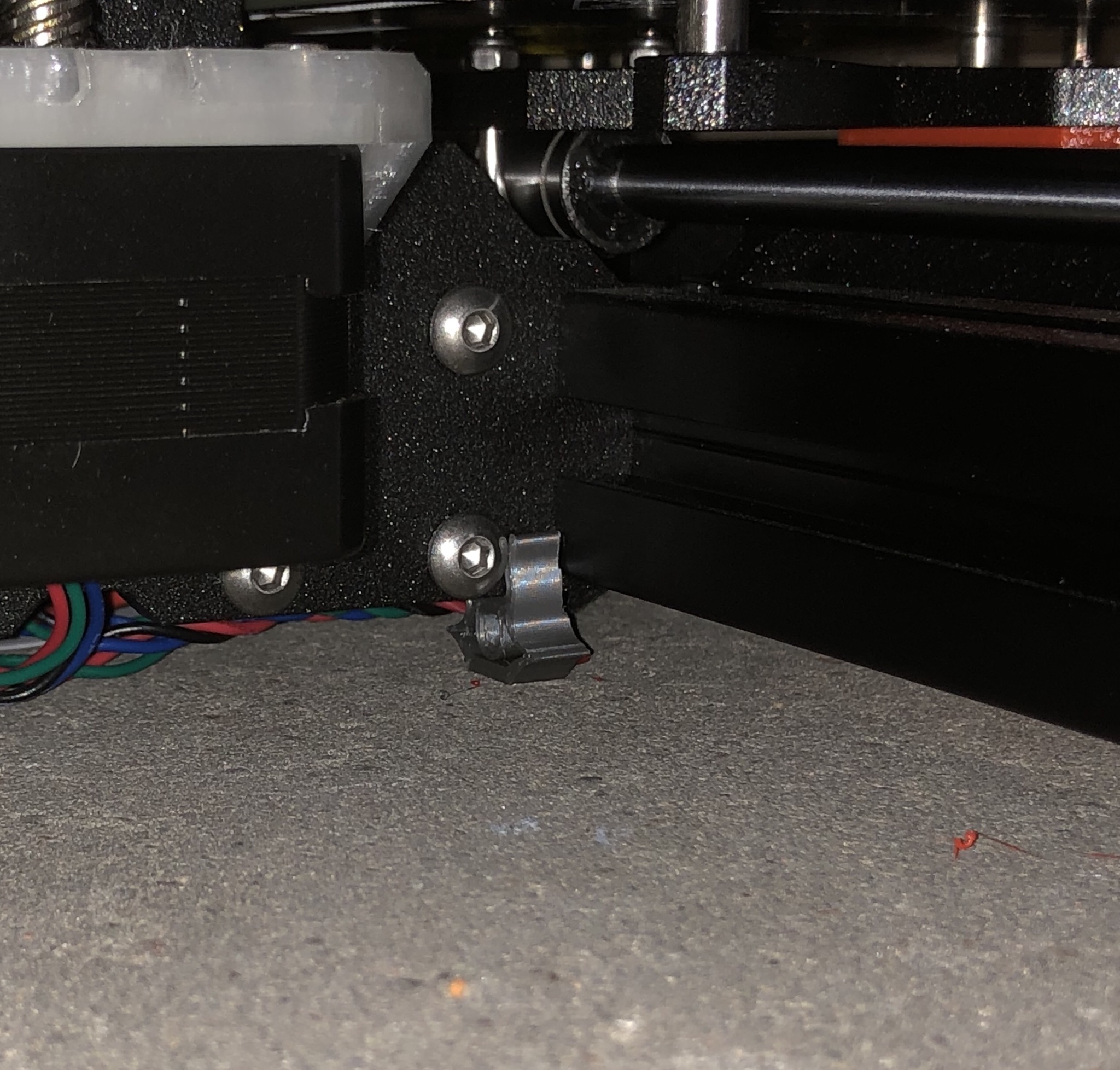
I made such a thing yesterday. Slips on frame between the two extrusions. Has some preload. Feel free to test. I noticed no difference but not running specific experiments. See Z foot:
Re: Z Axis Brace
Uh, clearly I was referring to it sitting on top of the feet, which are a the four corners, and causes the entire frame to be suspended.
I would just find some springs and put them under there to take up some (but not all) of the load.
I made such a thing yesterday. Slips on frame between the two extrusions. Has some preload. Feel free to test. I noticed no difference but not running specific experiments. See Z foot:
https://www.thingiverse.com/thing:2772947
Nice work!
Re: Z Axis Brace
Uh, clearly I was referring to it sitting on top of the feet, which are a the four corners, and causes the entire frame to be suspended.
I would just find some springs and put them under there to take up some (but not all) of the load.
I made such a thing yesterday. Slips on frame between the two extrusions. Has some preload. Feel free to test. I noticed no difference but not running specific experiments. See Z foot:
https://www.thingiverse.com/thing:2772947
Hi! Could you post a picture on how to use your Z brace? Thanks
Nothing fancy. No claims that it helps.
Re: Z Axis Brace
RHD only has 24 hours a day. 8 of them I have reserved for sleep and then I want a moment to relax with a glass of whiskey 😮
But remaining time may be enough to look at the Z axis again 😀
Currently I am doing fine tuning of the project "Fine tune your MK3".
lol I understand completely, just wanted to shout out for your work. 🙂
Does it vibrate as much with the spool on it?
Im still waiting for mine but am undecided on if i should mount the spool to the wall or the printer. One would think removing it from the printer would be better for vibrations but if its designed to be used as a counterweight and dampen vibrations that may not be the smartest move to remove it.
I have been considering this as well, but I don't see how the spool holder up top could reliably cancel things out at all times. I have been thinking about making a phone mount for the top bracket of the prusa and doing some accelerometer testing, maybe we can test it? Will get started modelling it after I rebuild my X axis today. 🙂
I wouldn't think they would use it for this purpose either. As the spool rotates weight may not be distributed well and as the spool reduces in quantity that would change it's original characteristics from a full spool.
The spool would vibrate at it's own constant and increase the issues I would think.
Re: Z Axis Brace
I've been following this thread because I thought the rubber feet might be causing some of the low frequency vibrations in the machine while it was running. So I did an experiment. I printed some "hard" feet and ran an x-y build test with a part I made just for the test. I didn't use the standard test block because I was too lazy to pull the petg out of the printer. It seems to have worked out fine for the test. I built the part with a pause in the middle to change the feet from the rubber oem's to the hard feet I made. It seems to make a difference. I replaced the 4 rubber bits with 6 hard bits. 4 in their original locations and 2 placed just in front of the z axis plate. They had a larger effect on the y axis than the x. Pics:
Re: Z Axis Brace
The hard feet. Simple design with a plug in and half turn. Just a quick exercise to try the idea. They are made of pla with a 50% fill rate. The center of the bottoms were recessed to accept self adhesive vinyl bump pads. the pads are 13mm od x 4mm thick and are standing 0.1mm proud. They limit the slip on the table.
Re: Z Axis Brace
I've been following this thread because I thought the rubber feet might be causing some of the low frequency vibrations in the machine while it was running. So I did an experiment. I printed some "hard" feet and ran an x-y build test with a part I made just for the test. I didn't use the standard test block because I was too lazy to pull the petg out of the printer. It seems to have worked out fine for the test. I built the part with a pause in the middle to change the feet from the rubber oem's to the hard feet I made. It seems to make a difference. I replaced the 4 rubber bits with 6 hard bits. 4 in their original locations and 2 placed just in front of the z axis plate. They had a larger effect on the y axis than the x. Pics:
Hot damn, you just found a huge contributing factor to that vertical line issue. 🙂
I wonder what would happen if we re-positioned the rubber feet closer to the center? Also, any chance I could grab that hard feet STL? May want to do some modification and see about sticking felt on the bottom of them.
Thanks!
My MK3 Parts: [Bowden] [New Shoes] [TPU Micro Springs]
Re: Z Axis Brace
Got some of these on the way, should be in Thursday. https://www.amazon.com/Sorbothane-Hemisphere-Non-skid-Adhesive-Durometer/dp/B00AJ1PI66/ref=sr_1_5?ie=UTF8&qid=1519171513&sr=8-5&keywords=sorbothane
My MK3 Parts: [Bowden] [New Shoes] [TPU Micro Springs]
Re: Z Axis Brace
Hot damn, you just found a huge contributing factor to that vertical line issue. 🙂
I wonder what would happen if we re-positioned the rubber feet closer to the center? Also, any chance I could grab that hard feet STL? May want to do some modification and see about sticking felt on the bottom of them.
Thanks!
Just a note from experience, felt is very slippery. It is usually used to protect one object from scratching another but it slides easily across a surface. The bump pads referenced do not slip, they 'grab' which I believe is the desired result. Google " clear rubber bumper pads " and you should find them.
- MK3s w/Mosquito Hotend- Mini w/Copperhead Hotend- XL - 5 tool -OpenScad -3d Builder -FreeCAD -Alibre -OctoPrint/x3(Pi3B)
Re: Z Axis Brace
I've been following this thread because I thought the rubber feet might be causing some of the low frequency vibrations in the machine while it was running. So I did an experiment. I printed some "hard" feet and ran an x-y build test with a part I made just for the test. I didn't use the standard test block because I was too lazy to pull the petg out of the printer. It seems to have worked out fine for the test. I built the part with a pause in the middle to change the feet from the rubber oem's to the hard feet I made. It seems to make a difference. I replaced the 4 rubber bits with 6 hard bits. 4 in their original locations and 2 placed just in front of the z axis plate. They had a larger effect on the y axis than the x. Pics:
Hot damn, you just found a huge contributing factor to that vertical line issue. 🙂
I wonder what would happen if we re-positioned the rubber feet closer to the center? Also, any chance I could grab that hard feet STL? May want to do some modification and see about sticking felt on the bottom of them.
Thanks!
Hi. Having fun. This printer works well but is turning into a hobby. Not complaining. I'm having trouble attaching a .stl. I'll put them up on Thingiverse and come back to drop a link..
Thingiverse link: https://www.thingiverse.com/thing:2801248
Re: Z Axis Brace
Got some of these on the way, should be in Thursday. https://www.amazon.com/Sorbothane-Hemisphere-Non-skid-Adhesive-Durometer/dp/B00AJ1PI66/ref=sr_1_5?ie=UTF8&qid=1519171513&sr=8-5&keywords=sorbothane
They look great. Anything that is higher durometer/hysteresis would help I think.
Re: Z Axis Brace
Uh, clearly I was referring to it sitting on top of the feet, which are a the four corners, and causes the entire frame to be suspended.
I would just find some springs and put them under there to take up some (but not all) of the load.
I made such a thing yesterday. Slips on frame between the two extrusions. Has some preload. Feel free to test. I noticed no difference but not running specific experiments. See Z foot:
https://www.thingiverse.com/thing:2772947
Hi jltx,
Printed these out tonight, but they are too tall. With these on and the front feet touching, my back feet are in the air by 1mm'ish. With the revelations David has found in this topic and the percentages of people having the issue vs not, I am starting to think Prusa may have pulled another fast one and sent some of us different feet than others. I have a big print going at the moment, will get a pic of the rubber feet I have once it completes.
My MK3 Parts: [Bowden] [New Shoes] [TPU Micro Springs]
Re: Z Axis Brace
Got some of these on the way, should be in Thursday. https://www.amazon.com/Sorbothane-Hemisphere-Non-skid-Adhesive-Durometer/dp/B00AJ1PI66/ref=sr_1_5?ie=UTF8&qid=1519171513&sr=8-5&keywords=sorbothane
They look great. Anything that is higher durometer/hysteresis would help I think.
Glad I sprung for the 8 pack, just found this: https://www.sorbothane.com/Data/Sites/31/pdfs/product-guides/Sorbothane-SPG.pdf
Looking like the 1" hemispheres at 50 duro need between 2lb and 4lb load to be effective. Thinking one in each corner plus two towards the center of the machine (six total) should put me in that sweet spot with or without a spool up top. I think eight feet might be too little load per isolator.
Can't wait to see your results. Hope they work. Better final solution and more generally available. The pla feet I ran the test with will probably need to be replaced because of creep.
Re: Z Axis Brace
What if you put only 3 feets instead of 4 ? Wouldn't it be more stable ? like a stool
Re: Z Axis Brace
Uh, clearly I was referring to it sitting on top of the feet, which are a the four corners, and causes the entire frame to be suspended.
I would just find some springs and put them under there to take up some (but not all) of the load.
I made such a thing yesterday. Slips on frame between the two extrusions. Has some preload. Feel free to test. I noticed no difference but not running specific experiments. See Z foot:
https://www.thingiverse.com/thing:2772947
Hi jltx,
Printed these out tonight, but they are too tall. With these on and the front feet touching, my back feet are in the air by 1mm'ish. With the revelations David has found in this topic and the percentages of people having the issue vs not, I am starting to think Prusa may have pulled another fast one and sent some of us different feet than others. I have a big print going at the moment, will get a pic of the rubber feet I have once it completes.
Interesting. They are designed to sag (preload) under weight. Works for me. I’ll take a look.