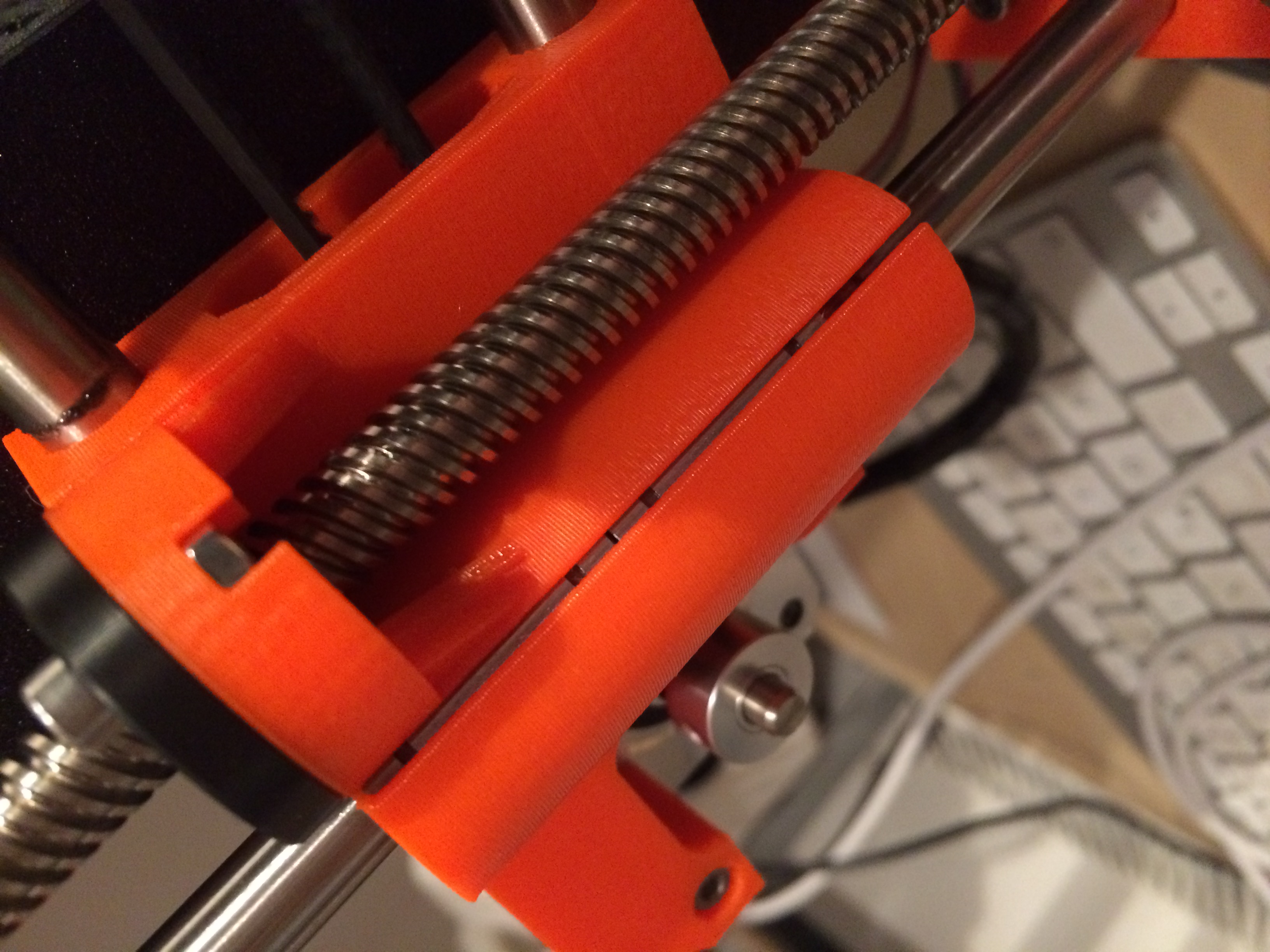
Problematic tolerances on x axis printed part
Hi
I just finished my MK3 kit and did a first print.
I noticed that as soon as the axis moves down in z that the bottom linear bearing on the left part moves up instead of staying where it should stay.
I have been so cautious with the build and my only conclusion is that the tolerance on this part is to sloppy.
On a YouTube video I saw another MK3 where the top bearing was falling down.
I guess these moving and then asymmetrical bearings have a negative impact on print quality.
So it is a small Problem. But a problem!
What would be the solution? Have Prusa fix tolerances and send me a replacement part?
Best regards
Christoph
Re: Problematic tolerances on x axis printed part
You could reprint the part to try it first. I believe the parts are all listed here in printable form.
https://github.com/prusa3d/Original-Prusa-i3/tree/MK3/Printed-Parts/stl
If this is your first 3d printer of this type, you can expect to reprint items over time, or perhaps for improvements from the community. Its kinda part of the process.
There should not be a lot of force on these bearings at all. Hopefully everything works out well for you, and you love your new printer.
Re: Problematic tolerances on x axis printed part
Great picture!
The fix:
The inner diameter of these two end parts should have an tiny inner rounded ridge printed into them to allow the bearing circlip grooves to grab onto them when they are pressed into the bore. That would hold them in place.
I saw this issue when first reviewing the MK3. I wasn't sure how much bearing part bore tolerance they could print in to hold the bearings in place.
MK3 Kit, Designed, built 4x4 CNC Plasma Cutting Table, Motorcycles Bigdogbro's Adventures
http://www.youtube.com/channel/UC5djrxBeeOKB9_6rHnn6G8A
Re: Problematic tolerances on x axis printed part
Something like these circular ridges in the inner bore. (cross sectional view) Very small and maybe only on one portion of the bore so the part doesn't need to spread so far open when pressing in the bearing.
If the ridges are on the inner grooves then each bearing can be pushed in from each end without having to push past the first leading bearing groove.
OR small grooves in the part and slide in a small wire into the circlip grooves to lock the bearing to the printed part.
If you ever need to remove the bearings chances are you will break off the ridge because the bearing has no chamfer in the circlip grooves and the ridge will get sheared off.
MK3 Kit, Designed, built 4x4 CNC Plasma Cutting Table, Motorcycles Bigdogbro's Adventures
http://www.youtube.com/channel/UC5djrxBeeOKB9_6rHnn6G8A
