My MK3 Power Mgmt Upgrade
.
Quick photo dump first, long winded write-up to follow...


My MK3 Power Mgmt Upgrade
.
After replacing my burned out stock MK3 PSU with a warranty replacement, I was left wanting: 1) A PSU that I can trust to not die, that has more headroom, and is super quiet… and 2) Good visibility into the power performance of the printer and PSU. In this post I’ll share some details of what I’ve done to achieve those things. I realize this is far more effort than most of you likely care to spend on power management, but some may find it interesting nonetheless. This is not intended as a step-by-step or a ‘how-to’, but I can try to answer questions if anyone cares to know more.
❗ Customary Disclaimer: I am not a certified electrician, nor am I giving you advice on what you should do in your own environment. Do not attempt anything like this unless you are capable of designing your own power circuits in a safe manner. If you choose to experiment on your own, I am not responsible for any damage to your self, your home, or your equipment (nor any voided warranties) that may result. 🙂
THE PSU
I’ve mentioned much of this in other threads, but I’ll recap here. I decided to permanently ditch the PRUSA PSU for a Meanwell. Mostly because I no longer trust the stock PSU to not burn out while I’m away from the house, but also because I don’t like operating PSUs at maxed out capacity in general. I’ve never had a failure of any of the 5 Meanwells I own, so I’ve come to trust the brand. I went with the SP-320-24 for its extra headroom and active PFC. The downside of this model (as with many 300+ watt PSUs) is the fan, which in itself is a bit noisy (although I prefer fan noise to the clicking and rattling of the stock PSU). Fortunately I had already planned to remote mount the PSU (after I noticed the stock PSU visibly warping the frame each time I fastened it down), but the fan noise made me want to remote mount the MW even further away. And that’s what lead me down the rabbit hole below.
CONCEPT
My home office looks a lot like a Radio Shack store that was recently searched by the FBI, so I don’t have a lot of extra room in here to begin with. So I decided to follow the path that a lot of my other cabling follows, which is downward. Directly below my office is my workshop (which is unfinished basement space), so I have very easy access to run wiring. This is also where my rackmount Smart-UPS 1500 sits, which serves all of the gear in my office above. So I thought if I’m already going to do some wiring and soldering for this project, what else can I do to improve my end result? Firstly, since the MW is now going to be down in the basement, I would want a way to remotely power it on and off. Next, an extra bonus for me is that when I’m not using my printer I can make use of that 24v for electronics projects on my work bench upstairs. So that meant I would need some sort of junction box near my bench with a power tap. Because I might be using the PSU for things other than the printer, I would want a switch so I could disconnect the printer independently while leaving the PSU still running. I would also want a local indicator that the PSU is putting out power (besides turning the printer on to check), so I can add an LED on the box for that. And I saved the most important for last, I want more visibility into my power usage, so I need: 1) a way to measure power on the 110v AC side of the circuit (between mains and PSU), and 2) a way to do the same on the 24v DC side.
ASSUMPTIONS
Current Capacity:
I measure the peak DC current draw of the MK3 with my bench multimeter right at 10.2amps (beginning of preheat). Typically the printer is drawing far less than that, somewhere between 2amps and 6amps while printing. Although the preheat phase doesn’t last very long and it occurs seldomly compared to actual printing time, I will use 10amps as my ampacity requirement across the board. This will result in a degree of over-engineering of the circuit in a normal operating scenario, but I like to be well into the safe zone with power circuits. I am factoring possible “what if” scenarios into that decision, such as a firmware bug or an Octoprint error that somehow gets the heatbed and extruder stuck in a ‘full current’ condition. The goal of course is to avoid blowing fuses, melting wires, fusing switches, or at worst case causing a fire.
Power-Panic:
When I designed a conversion case for my MW PSU, I removed and re-used all the components from the PRUSA PSU case, including the power panic module. That said, I don’t feel the need for the power-panic feature as I am running the printer on a rather large UPS. So while I believe the power-panic module is functional on the MW, I’m going to leave its black/white wire coiled up inside the PSU case and not extend it up to the printer in the office.
EQUIPMENT
As mentioned I already had my Smart-UPS 1500 and the Meanwell SP-320-24. I also had an extra Kill-A-Watt unit on hand, which I’ll use to measure the AC side of the circuit. I’ll print my own junction box and frame mount for the multimeter, so that left me needing the following:
Wiring:
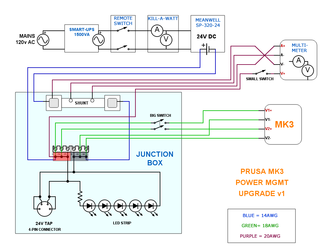
I bought small spools of 14, 18, and 20 gauge wire for this project. (I’ve been buying silicone coated wire recently, as its more flexible and easier to route.) To make the cabling easier from the basement to upstairs, I decided to run only one pair of wires to carry the 24v (as opposed to the 2 pair coming from the stock PSU). This is okay to do because the MW SP-320 is a single output PSU, so it only has one rail supplying all 320 watts (all three screw terminals are on one leg). However to support that combined amperage on a single pair and not incur a big voltage drop (especially with a longer cable run) I need to increase the wire gauge. So I’ll run 14awg from the PSU to my power junction box upstairs. Also, I helped minimize the cable run by mounting the PSU on top of my coke machine in the basement, so this 14awg feed is only about 8 feet total length. Once inside the junction box, I’ll split the circuit into separate legs, meaning far fewer amps per wire…so I’ll transition to 18awg for some of the wiring inside the box, and from the box to the printer itself. Lastly, I’ll use the 20awg for the remote wires that run from the junction box up the frame to the multimeter, as there is very minimal current here.
Remote power switch:
I picked up one of these remote controlled AC power boxes on Amazon. The lower of its two amperage ratings is 8amp, which is far more than adequate for my MW (320watts / 120volts = 2.66amps)
Hardwired DC multimeter:
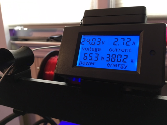
I like the look of this multimeter because it has a simpler screen than some of the others available. It shows volts/amps/watts and keeps a resettable cumulative tally of energy consumed in watt-hours (and stores that measure even after the power is cut, which is nifty). I went with the model that has an external shunt, which give it a capacity up to 100amps. Because the MK3 power consumption peaks out at ~10amps, you could get away with different model that includes a smaller (20amp) internal shunt. However there is a good reason I didn’t go that route. I wanted to remote mount my multimeter up top on the frame of the printer. A multimeter with an internal shunt requires that the full amperage of the circuit you are measuring flows directly through the unit itself. So in this case I would have to route a beefier wire carrying up to 10amps up and back down the frame of the printer, which is no bueno. However with an external shunt, the full amperage of the circuit only has to run through the shunt (which I can locate inside my junction box), and then run remote wires from the shunt up the frame to my multimeter. These remote wires carry exponentially less current and can therefore be much thinner and more easily routed.
Large Switch:
This switch will be mounted in the junction box and will serve as my local power disconnect for the printer. I always have a small collection of switches on hand, but I did not have any that I felt comfortable running 10amps through. If you know much about DC power and small electronics, you’ll know that 10amps is a much higher than average amount of DC amperage. Most of your off-the-shelf switches are not rated for 10amps DC. In fact, many readily available switches have no specified DC rating at all, and only carry AC 110v/220v ratings. Note: AC ratings are NOT related to DC ratings in the way you might think. You cannot simply use Ohm’s law for this. The DC amperage a switch can handle without failing is far less than the AC amperage it can handle. If a switch says it can handle 10a @ 110v AC, it would be rated at far less than 10a @ 12v. On top of that, the ratings that switches typically shows will likely apply to a 12v circuit. Since we’re operating at 24v here, you have to further reduce that rating by about half as compared to 12v DC. I’ve found conflicting info online about how to precisely convert/compare switch ratings, so I won’t attempt to give you any advice on that. In the end I found a higher capacity rocker switch in my local shop that I was comfortable running 10amps @ 24v DC through.
Terminal Block:
Not the most elegant way to combine all these wires, but I find these terminal blocks to be super convenient. You definitely want one with jumpers for this type of application, so you can bridge several terminals together to form your rails.
24v Tap:
To pull 24v off of the box for my work bench, I used a common 4-pin connector that I had laying around.
LED:
I had plenty of LEDs laying around that are prewired with resistors for 12v operation. Since we’re at 24v, to keep the LED from burning out I’ll just need to add another resistor in series to make up for the extra 12v differential.
Small Switch:
Not totally necessary, but I decided it would be nice to have a small switch on the side of the multimeter to be able to independently turn it on/off. On top of that, I had this tiny little rocker switch on hand that I really wanted to use for something, and it ended up being a great fit for this.
Wire Wrap:
I have lots of this stuff, which is what I'm using to redo the wraps on my printer as well. I used it to protect the 24v feed running from downstairs, and to tidy up the cables to/from the box. I used standard heat shrink wrap for the wires up the frame to the multimeter.
PUTTING IT TOGETHER
I started with designing and printing the junction box and the frame mount for the multimeter so I’d have destinations for the wires I needed to run. My main design constraints for the box were the sizes of the shunt, the terminal block, and the rocker switch on the side. I also made small holes on the side for the indicator LED and the 4-pin connector for the power tap. After the box was printed, I epoxied the shunt and terminal block inside, and began making all the internal connections. I used 14awg on the main circuit path through the shunt to the terminal block. At the terminal block is where I split the circuit into multiple legs and transitioned to 18awg. My large switch is a DPST, meaning it has two legs. So I took advantage of that and ran two 18awg wires to it, and two wires back out for the 24v feed to the printer. The multimeter requires 4 wires: one from each of the two small terminals on the shunt, one from the large negative terminal on the shunt, and one from the positive rail of the power source. As I mentioned, these four wires are carrying a tiny amount of current, so I used some really flexible 20awg silicone coated wire for this, to make routing up/down the frame easier. After these four wires enter my multimeter mount, the V+ lead is interrupted by the small rocker switch I mounted there, so I can power off the meter as desired. I then mounted my LED in the box, added two resistors in series on its positive leg (I didn’t have one resistor of the proper size so I combined two), then connected it to the terminal block. Lastly I mounted my 4-pin connector in the side of the box, and connected it to the terminal block as well. I bridged 2 of its wires together for positive and two for negative, to increase its current capacity.
All that was left was to connect up the main feed wires to the MW and test her out. I left the printer disconnected for this part of course, and used my bench multimeter. After successful testing, I cut the power, connected the printer, and fired it back up. Voila. Power management level up!
FLOSSING IT UP 😎
The single blue LED on the side of the box wasn’t quite doing it for me, so I figured I’d bling it out a little. I stenciled a sweet design in the cover and backlit the box with a couple snippets of RGBW LED tape I had laying around. Cuz why not? LEDs make every project better.
CONCLUSIONS
Comfort factors:
I have to say I really like being able to see what my printer is doing from a power perspective at any given time. But more importantly, I’ve given myself more confidence about leaving my printer running while I’m away. Due to the fact that I trust this brand of PSU, and that I’m never running this unit at its max capacity, I have no reason to think it will burn out prematurely.
PSU Efficiency:
When my Kill-a-Watt reads 279watts between mains and the PSU, the multimeter reads 240watts of between the PSU and the printer. Those measurements give the MW around an 86% efficiency rating, which is very close to the 87% rating that is listed on its spec sheet. This makes it slightly more efficient than the stock PRUSA PSU according to some of my initial testing, but not by much. The stock PSU consistently measured in the 80-83% range for me.
Noise Reduction:
Oh the beautiful quiet! Now that I can't hear the PSU at all, the MK3 is insanely quiet. It’s really amazing how much of my noise was coming from the stock PSU (and for a few days, the fan on the MW). That said, I also have my filament spool off the frame now, and the printer is sitting on a thick rubber mat, so I’m seeing a lot less vibration in general than I was before. All I can hear now is the steppers and the extruder’s fans, it’s so very nice.
My MK3 Power Mgmt Upgrade
Here's a rough sketch...
Re: My MK3 Power Mgmt Upgrade
Looks good.
Since you relocated the PSU, you should reinforce the frame as the PSU had provided that function. There are many ways. I made a brace for this purpose which you can find in the link in my sig.
Re: My MK3 Power Mgmt Upgrade
Looks good.
Since you relocated the PSU, you should reinforce the frame as the PSU had provided that function. There are many ways. I made a brace for this purpose which you can find in the link in my sig.
Thanks jltx. I've actually printed out your supplemental brace already, just haven't installed it yet.
Re: My MK3 Power Mgmt Upgrade
...
Looks good.
I'm ordering the MeanWell RSP-320-24 as well for my DIY MK3.
How's the fan noise of the PSU? some people said it would be noisy.
Also this shows Prusas 240W PSU is awfully underpowered.
244W draw during warmup, while the PSU is certified for 240 - 242watts. (even if josh connected some LED strips)
There should be a least 20-25% of unused overhead for the power
PC builders usually leave a 100-200watt unused overhead (System draws 350 watts at peak, get a 550watt PSU)
This also explains why so many of the original but cheap LED PSUs burst into flames or shut the printer off during Heatbed PWM
Btw josh, did you measure how many ohms the heatbed has?
Re: My MK3 Power Mgmt Upgrade
I like it Josh. Nicely done.
Re: My MK3 Power Mgmt Upgrade
Thanks guys.
@devilhunter I have the SP, not the RSP. They might sound exactly the same, but I can only speak to the SP-320. The fan is definitely louder than I wanted. My first thought was to mount it under the desk, but I'm not sure how much that would have helped.
No, I didn't measure the ohms on the bed. I did see that someone posted that value in one of the other power supply threads though.
Re: My MK3 Power Mgmt Upgrade
Nice idea !
But, the long wires are not an advantage, the shunt of the amperemeter also. Have your new PSU an sense wire ? How much voltage drop is at the shunt ?
Problem is the drop of the voltage while drawing high current. This can result in some artefacts of printing, like ripples, banding, ...
Make the main cables from PSU to wiring box and printer as big as possible and as short as possible. 14AWG is not enough, I recommend 10AWG and more ! 18AWG is by far much too less !!!
Solution : Use an sense wire (if the PSU has one)
(the MW-500-24 has remote sense)
Example : 10A by 0.1Ohm result in 1V voltage drop 😮
Thomas
Re: My MK3 Power Mgmt Upgrade
I agree with the short wires. Keep the wires from the PSU to the Einsy to the Heater Elements as short as possible. Even a +30cm in length can result in 10-20% power loss.
I used 4mm copper cables from the PSU and soldered them down on the Rambo and the Heatbed.
Btw, i just measured my heated bed and the heater cartridge in the hotend.
Heated bed measures about 3 Ohms.
3 Ohms @ 24V results in a 192W of power draw, or 8 ampere
e3d heater cartridge measures 15.4 ohms
15.4 Ohms @ 24V is 37.4W of power, or 1.55 ampere
The Einsy with the added motors in idle is about 12 watts of power draw
All motors going we should see another power draw of 6-8 watt
So that leaves us with a complete power draw of 250 watts for a 240 watt PSU.
(in worst case scenario, when the heated bed is heating)
Since the bed and hotend are PWM modulated, this will result in multiple sharp power spikes per second.
For these peaks you should leave some headroom.
I once converted my MK2 to usa power from a 500watt ATX power supply, but the ATX couldn't keep up with the power spikes and the added LEDs on the 12V rail flickered a lot.
LED PSUs seem like the better choice for 3D Printers, because of the high and short power draws.
In a PC, the components like the CPU and GPU will ramp up the need for power, not draw it instantly like a short circuit that the heated bed and the power cartridge is.
My point:
Prusa PSU = too short dimensioned for these power spikes.
Re: My MK3 Power Mgmt Upgrade
Nice idea !
But, the long wires are not an advantage, the shunt of the amperemeter also. Have your new PSU an sense wire ? How much voltage drop is at the shunt ?
Problem is the drop of the voltage while drawing high current. This can result in some artefacts of printing, like ripples, banding, ...
Make the main cables from PSU to wiring box and printer as big as possible and as short as possible. 14AWG is not enough, I recommend 10AWG and more ! 18AWG is by far much too less !!!
Thanks for the comments. Funny, I upgraded the wires between the wiring box and the EINSY to 14awg just yesterday. I had extra leftover 14awg, and I wasn't happy with the voltage drop I was seeing at the printer with the 18awg wires. (Incidentally, I'm pretty sure the stock PRUSA PSU cables are 18awg).
Now that I'm 14awg from the PSU all the way to the EINSY, the largest voltage drop I see is 23.4v (measured at the EINSY), but only for the first 60 seconds of preheat while the printer is drawing ~10amps. Toward the end of preheat, I'm back up at 23.6v already. And during normal printer operation I almost never see the voltage drop below 23.7v.
23.4 is a 2.5% voltage drop, and 23.7% is a 1.25% voltage drop. I was under the impression that <3% drop would be totally acceptable with this kind of equipment. I routinely see 2-3% voltage drops in many of my other 12v and 24v DC equipment without issues. The EINSY specs say it accepts 10v-24v. Are you saying it does not have enough buffer to absorb a <3% voltage drop during printing without affecting print quality?
Re: My MK3 Power Mgmt Upgrade
Wow I like this idea. I ordered up a MW Mean Well SE-600-24 power supply for it. I have the same worry and I figure that more than double the output current then the power supply doesn't have to work hard. Going to run 8ga between the power supply and the junction box figure once again bigger is better. The power supply has remote sense so I will run that to the junction box so if there is any voltage drop it will adjust for it. I even have the shunt and meter you talk about. Going to have to design up the same box and mount idea you did guess it will the first thing I print once I get my mk3 don't expect it till the end of march. 😀
Mark
Thanks Mark, glad you like it. I have been experimenting with thicker gauge cabling as well, to see how much it positively affects voltage drop. Will make a follow-up post once I decide what size wiring I'll use permanently.
Re: My MK3 Power Mgmt Upgrade
one question, did you use fusion 360 to layout the boxes?
Re: My MK3 Power Mgmt Upgrade
one question, did you use fusion 360 to layout the boxes?
The power box I did. I'll post the file below.
The box for the multimeter I kludged together from two existing STLs. Total hack job, but it got the job done. 😉
Re: My MK3 Power Mgmt Upgrade
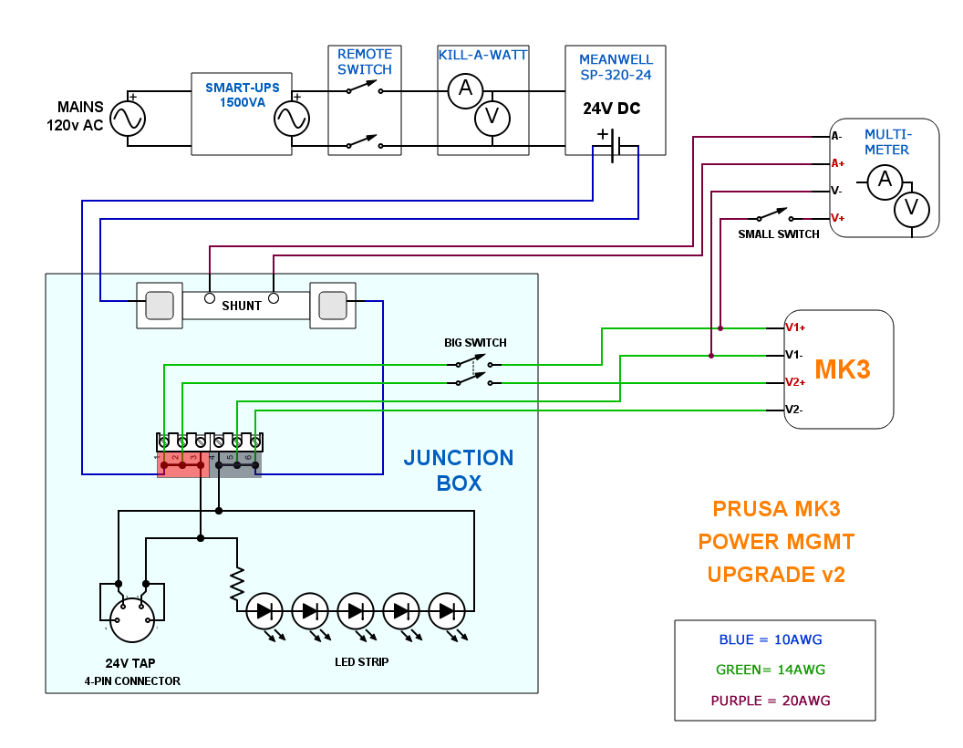
Reporting back on wire gauge and voltage drop. After doing some testing with various wire thicknesses, I ultimately decided to go with 10awg from my remote mounted Meanwell to my power junction box, and 14awg from the box to the EINSY. With that configuration, the lowest voltage I see now is 23.6v (1.6% drop), and only when preheat is initially drawing 10.2amps. After preheat, the lowest voltage I see during printing is 23.9v (0.4% drop)...but most of the while it's dead on at 24v. I'm happy enough with those numbers.
The other change I made is the connection point of the multimeter voltage leads. I'm now connecting at the EINSY terminals, as I'm more interested in the specific voltage at the printer than in the junction box / accessory plug.
Updated schematic below.
Re: My MK3 Power Mgmt Upgrade
...
The other change I made is the connection point of the multimeter voltage leads. I'm now connecting at the EINSY terminals, as I'm more interested in the specific voltage at the printer than in the junction box / accessory plug.
Updated schematic below.
MK3 Pwr Mgmt Schematic.png
IMG_9112.JPG
Looks nice.
How does the voltage your reading compare to the voltage in the menu at support/voltage?
Re: My MK3 Power Mgmt Upgrade
i would take a FLIR (A Cx or Ex series at least) and check the PSU hot zones. if they're only the transistors there's no reason to just add heatsinks and have it cool passively. especially if you're not running at capacity. i put a noctura in one of mine and also dropped it's speed to near silent levels. it's on some Chinese 350w 24v supply but the thing never really gets hot as it only uses 250-260w during heat up anyway.
Re: My MK3 Power Mgmt Upgrade
Looks nice.
How does the voltage your reading compare to the voltage in the menu at support/voltage?
Thanks.
The EINSY internal voltage reading within the Support menu always reads 0.1-0.2v lower than my mounted multimeter. And somewhere in the middle is where my handheld multimeter will register. For example:
23.9v (EINSY) <== 24v (HANDHELD) <== 24.1v (MOUNTED)
Re: My MK3 Power Mgmt Upgrade
i would take a FLIR (A Cx or Ex series at least) and check the PSU hot zones. if they're only the transistors there's no reason to just add heatsinks and have it cool passively. especially if you're not running at capacity. i put a noctura in one of mine and also dropped it's speed to near silent levels. it's on some Chinese 350w 24v supply but the thing never really gets hot as it only uses 250-260w during heat up anyway.
Thanks for the feedback. You are a braver man than me, modding the cooling capacity of an off-brand Chinese PSU.
Part of my goal here was to increase reliability and decrease risk of failure/burning. While you may be right that the fan is overkill when not running at-capacity, second-guessing the Meanwell's cooling requirements was definitely not part of my thought process. To whatever degree possible, I like to keep my warranties un-voided, and my house un-burnt. 😉