Re: Improved fan shroud / nozzle
tried to print the duct with BDP / PLAtech yesterday... but the result was very poor (saggy is a good description). 😕
the later started abs print looked better... but failed due to a (still) missing enclosure for my printer(s).
I'm going to give it another chance with petg this evening 8-).
maybe it's a good idea to cut the part in two halves, print them seperately and glue them together afterwards.
dem inscheniör is' nix zu schwör...
Re: Improved fan shroud / nozzle
I printed mine with the orientation upside down relative to how it is fitted to the printer. Use support material from the print bed only. You need good cooling printing in this orientation because of when it starts to close the print it treats them as a bridge and some are fairly long. You can reduce some of the longer bridges by changing the bridging angle.
For my supports I have the Z distance contact set to 0.07mm and a solid interface layer. Don't support bridges. PE Slic3r 1.38.5.
I can't remember if I printed at 0.15mm or 0.2mm
On some of the radius the wall thickness is so thin I had to touch a little glue onto them because there were some very small gaps
Re: Improved fan shroud / nozzle
Awesome to hear that the design is being used but I'm a bit surprised that you report it as being saggy. When printed laying flat, I also had it be very saggy which ended up looking OK-ish from the outside but with threads hanging into the airstream from the inside. If the part is printed laying down flat, it will indeed have a lot of overhangs despite the internal rib. The only print orientation that I have gotten it to print good is standing such that the face from where you insert the screw is towards the build plate. This way, the overhang is only the thickness of the part at 10mm. 
To clarify, I've used a few of the failed prints to make a picture that hopefully illustrates the orientation that works and the one that doesnt. 🙂

Re: Improved fan shroud / nozzle
I already used the correct orientation, of course.
but at the upper surface I got some problems (even holes).
there is a small hole near the hole for the screw (behind the support pillar).
and at the shallow overhang before the round corners at the bottom, it's still not watertight.
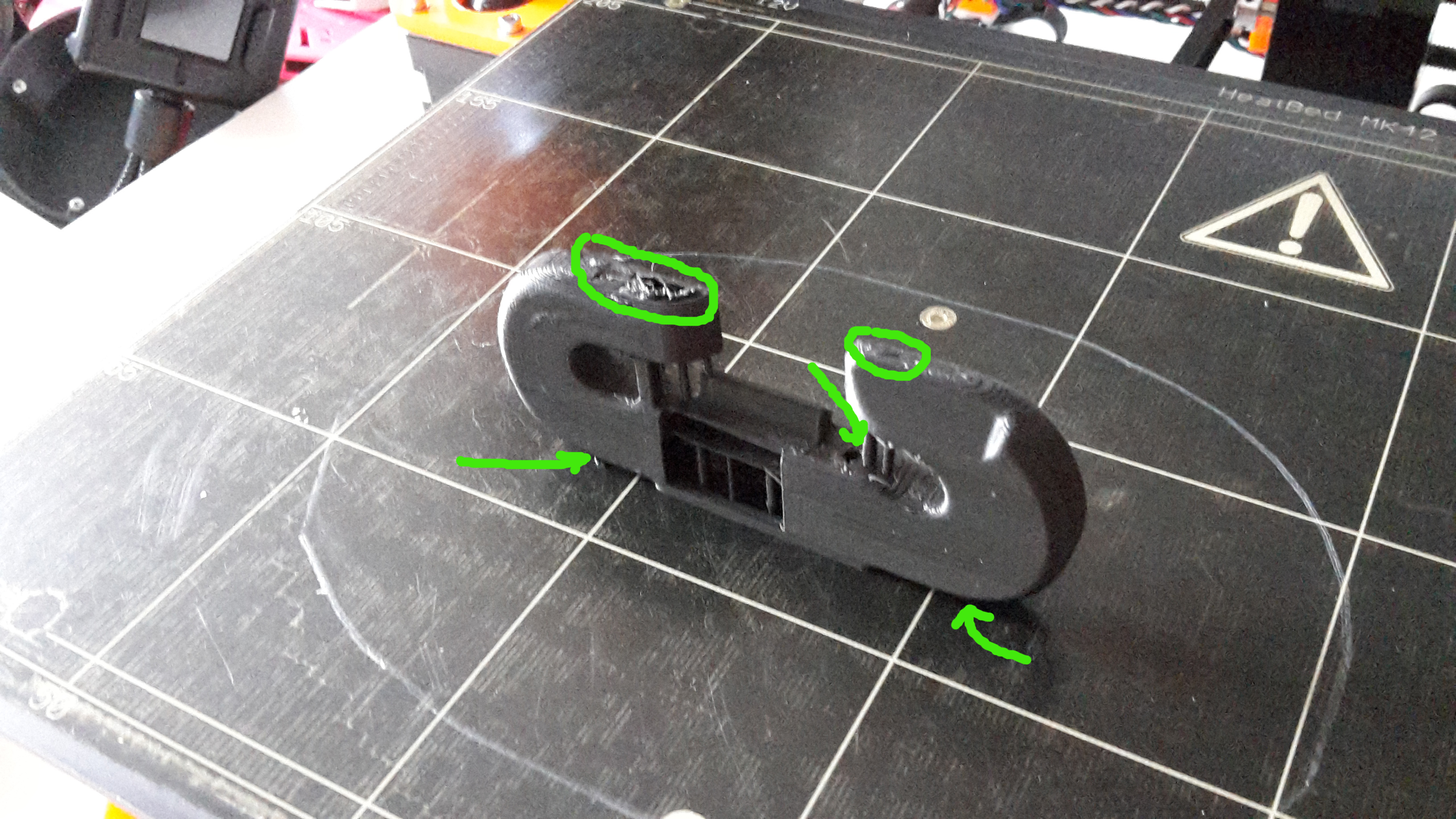
meanwhile I tried it to print it in petg. that's much better, but still shows the problems at the shallow edges of the bottom.
the prints that I've done so far are all with 0.2mm layer height.
I'm going to try a print @ 0.1mm height.
@Sebastian: maybe you can upload a *.gcode (sliced for PLA), so that we can check/improve our slicer (S3D & slic3r) settings for that particular model ?
dem inscheniör is' nix zu schwör...
Re: Improved fan shroud / nozzle
I already used the correct orientation, of course.
but at the upper surface I got some problems (even holes).
there is a small hole near the hole for the screw (behind the support pillar).
and at the shallow overhang before the round corners at the bottom, it's still not watertight.
20180105_115503.jpg
meanwhile I tried it to print it in petg. that's much better, but still shows the problems at the shallow edges of the bottom.
the prints that I've done so far are all with 0.2mm layer height.
I'm going to try a print @ 0.1mm height.
@Sebastian: maybe you can upload a *.gcode (sliced for PLA), so that we can check/improve our slicer (S3D & slic3r) for that particular model ?
I was able to print the shroud no problem in the recommended orientation. All I had were some crappy layers on the bottom (not using supports), and a few extra/weird lines in the screw hole that had to be removed. I sliced it with Slic3r (latest version) default settings for 0.15mm. Here's the gcode I used.
@sebastian.j
Two dumb questions for you man. 1) Why is the shroud so long? 2) Why is the venturi funnel so thick instead of being the bare minimum size shell wise? Isn't this unnecessary weight?
Re: Improved fan shroud / nozzle
Awesome to hear that the design is being used but I'm a bit surprised that you report it as being saggy. When printed laying flat, I also had it be very saggy which ended up looking OK-ish from the outside but with threads hanging into the airstream from the inside. If the part is printed laying down flat, it will indeed have a lot of overhangs despite the internal rib. The only print orientation that I have gotten it to print good is standing such that the face from where you insert the screw is towards the build plate. This way, the overhang is only the thickness of the part at 10mm.
To clarify, I've used a few of the failed prints to make a picture that hopefully illustrates the orientation that works and the one that doesnt. 🙂
My post wasn't clear. Mine sagged during use on the printer not while it was being printed. Was fine during the print.
Re: Improved fan shroud / nozzle
ok, maybe saggy wasn't the proper adjective (english isn't my native language)... brittle would have been better :geek:
dem inscheniör is' nix zu schwör...
Re: Improved fan shroud / nozzle
I already used the correct orientation, of course.
but at the upper surface I got some problems (even holes).
there is a small hole near the hole for the screw (behind the support pillar).
and at the shallow overhang before the round corners at the bottom, it's still not watertight.
20180105_115503.jpg
meanwhile I tried it to print it in petg. that's much better, but still shows the problems at the shallow edges of the bottom.
the prints that I've done so far are all with 0.2mm layer height.
I'm going to try a print @ 0.1mm height.
@Sebastian: maybe you can upload a *.gcode (sliced for PLA), so that we can check/improve our slicer (S3D & slic3r) settings for that particular model ?
Hmm, that was unexpected. I didn't have holes those places and only had negletible amount of ugliness on the outside of the shallow overhang. I did print mine at 0,15mm so it might be that 0,2mm is too coarse for the shallow slopes. I'm fairly convinced that the layer height is the culprit if your main issue is that the extrusion doesn't overlap the previous at shallow angles.
I don't have a gcode from the most recent design but i have for the one I printed which didn't have as many of the support columns. That one printed well apart from the overhangs seen in the pictures on thingiverse which caused the addition of the columns. That one is here https://www.dropbox.com/s/wefdndspi90lc4z/fan_nozzle_V3_upright.gcode?dl=0
If you want, I can fairly easily make the shallow overhang at the bottom less of an issue by letting all of that side touch the build plate but that would be at the cost of getting more square-ish corners.
I was able to print the shroud no problem in the recommended orientation. All I had were some crappy layers on the bottom (not using supports), and a few extra/weird lines in the screw hole that had to be removed. I sliced it with Slic3r (latest version) default settings for 0.15mm. Here's the gcode I used.
@sebastian.j
Two dumb questions for you man. 1) Why is the shroud so long? 2) Why is the venturi funnel so thick instead of being the bare minimum size shell wise? Isn't this unnecessary weight?
By shroud, do you mean the intake funnel or the duct after the fan? Both are made pretty much from my intuition and a few considerations of how stuff in industry looks like and what air behaves like.
The length of the funnel is made to more or less stick out as far as the extruder motor as I thought it made somewhat sense and was aestethically pleasing. It might be possible to make it a bit shorter and have a more agressive change in curvature but without CFD analysis I just drew something I thought made sense. The thickness of it is about the minimum I figured I could do without keeping the structure too flimsy and to make sure that noone would have issues with their slicer skipping parts due to too little wall thickness. Near the top of the funnel it is thicker than otherwise to have a change in curvature on the inside while still having the overhang on the outside being printable. The weight that could be saved off of the funnel by making it thinner is neglectible as the one I printed was only 35 grams and that was with excessive infill and amounts of perimeters on the center part. If you could save 0,5, 1 or 2 grams, that would be neglectible when the extruder motor weights several hundred grams.
The length of the air path in the duct is chosen a bit excessively to have rounded corners and a pretty constant curvature without abrupt changes. Because air has a low viscocity, the length of the air path doesn't contribute much to a drop in air pressure compared to the curvatures and the general shape of the air path. A sharp corner of the wall away from the airstream will cause the air to seperate from the wall and create a low pressure zone just on the edge of the corner which pulls the air in a way which is not intended.
A sharp corner of the wall into in front of the airstream will cause the air to pile up and stop before it changes direction to go where we want to. While this is a negative impact, it is not as influencial as the underpressure since an overpressure can only be lifted from atmospheric pressure by the dynamic pressure (0,5*density*velocity^2) while the negative pressure in an air seperation bubble will often be much lower than the atmospheric pressure and is much lower than the dynamic pressure is higher.
The general size of the duct cross-section has been kept as high as deemed reasonable for the curved section so that the air speed is low and both the viscous and pressure effects are as small as possible and the cross-section is then narrowed towards the side outputs as the air speed is then sped up to make sure that the airstream goes mostly in the pointed direction which is down onto the print. 🙂
Re: Improved fan shroud / nozzle
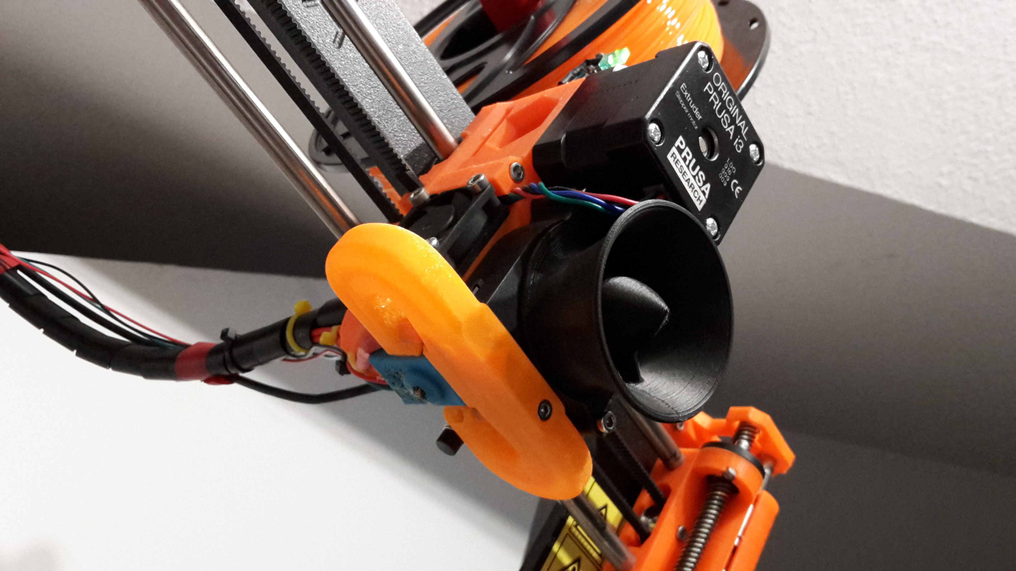
@Jakob: your gcode printed much better than mine ! even in spite of a different orientation from Sebastians proposal (90° turned counterclockwise).
no holes, just a slightly uneven/rough surface below the "horns".
going to print my next attempt with the new duct installed 🙄
yeah, the design would be easier to print if you extend the surface that touches the build plate until you can raise up an edge with an angle of 45° or above.
...
If you want, I can fairly easily make the shallow overhang at the bottom less of an issue by letting all of that side touch the build plate but that would be at the cost of getting more square-ish corners...
the "outer" design doesn't need to mach 1:1 the interior form of the duct... it only needs to surround it.
----
by the way: just printing the next attempt with the fan duct installed. looks curious to see such a big "boat" hovering over the build plate.
reminds me somehow at luke skywalkers x-34 landspeeder, that he sold for 2000 credits at mos eisley.
----
update:
the new duct changed the behaviour of the printer significant. but actually I'm not sure if its an improvement or not.
got severe stringing now when printing with the same settings for temperature and cooling-fan as before:

dem inscheniör is' nix zu schwör...
Re: Improved fan shroud / nozzle
You maybe want to check on this one...
https://www.thingiverse.com/thing:2578649
Re: Improved fan shroud / nozzle
just an update from my site:
the combination of E3D silicon sock with Sebastians duct simply doesn't match.
I guess there are vortexes at the edge of the silicon rim.
after disassembling the blue sock (needed to be replaced anyway) the next print got no problems with severe stringing (only a few strings, as usual).
@alexander.s27: maybe I'm going to try out your proposed duct as well, seems that the guy who designed this had the silicon sock in mind.
dem inscheniör is' nix zu schwör...
Re: Improved fan shroud / nozzle
just an update from my site:
the combination of E3D silicon sock with Sebastians duct simply doesn't match.
I guess there are vortexes at the edge of the silicon rim.
after disassembling the blue sock (needed to be replaced anyway) the next print got no problems with severe stringing (only a few strings, as usual).
@alexander.s27: maybe I'm going to try out your proposed duct as well, seems that the guy who designed this had the silicon sock in mind.
Any idea of what causes the duct to be incompatible with the sock?
I just added a silicone sock myself so if it doesn't work as intended with it, I'll change it so it does. Is it because it blows partially onto the sock so it would help to lower the top edge so the air is focused a bit more downwards? 🙂
After reading your comment I have just printed a file which is basically a spaghetti sized spiral as the continuous and slight overhang shows inefficient cooling. I've done so with an E3D silicone sock that fits over the entire nozzle and there are no artifacts to see as there was on the backside when I printed it with the stock fan duct. The g-code for that print is here and the print takes 15 minutes if anyone are curious to compare as this was the print that made it clear for me that the cooling on the far side is isufficient as original.
Re: Improved fan shroud / nozzle
that's what I assume. I guess that the duct is a little bit to high and the airflow primarily hits the edges of the block and the round rim. so the tip of the nozzle itself is not directly hit by a steady air stream (but maybe by vortexes).
.... Is it because it blows partially onto the sock so it would help to lower the top edge so the air is focused a bit more downwards? 🙂
....
---
by the way, the spiral "noodle" prints very nice, from all sides .
dem inscheniör is' nix zu schwör...
Re: Improved fan shroud / nozzle
that's what I assume. I guess that the duct is a little bit to high and the airflow primarily hits the edges of the block and the round rim. so the tip of the nozzle itself is not directly hit by a steady air stream (but maybe by vortexes).
.... Is it because it blows partially onto the sock so it would help to lower the top edge so the air is focused a bit more downwards? 🙂
....
---
by the way, the spiral "noodle" prints very nice, from all sides .
Then, could you share the print that made you suspect that the duct is not good when the socks are used? 🙂
Re: Improved fan shroud / nozzle
yes, of course.
....
Then, could you share the print that made you suspect that the duct is not good when the socks are used? 🙂
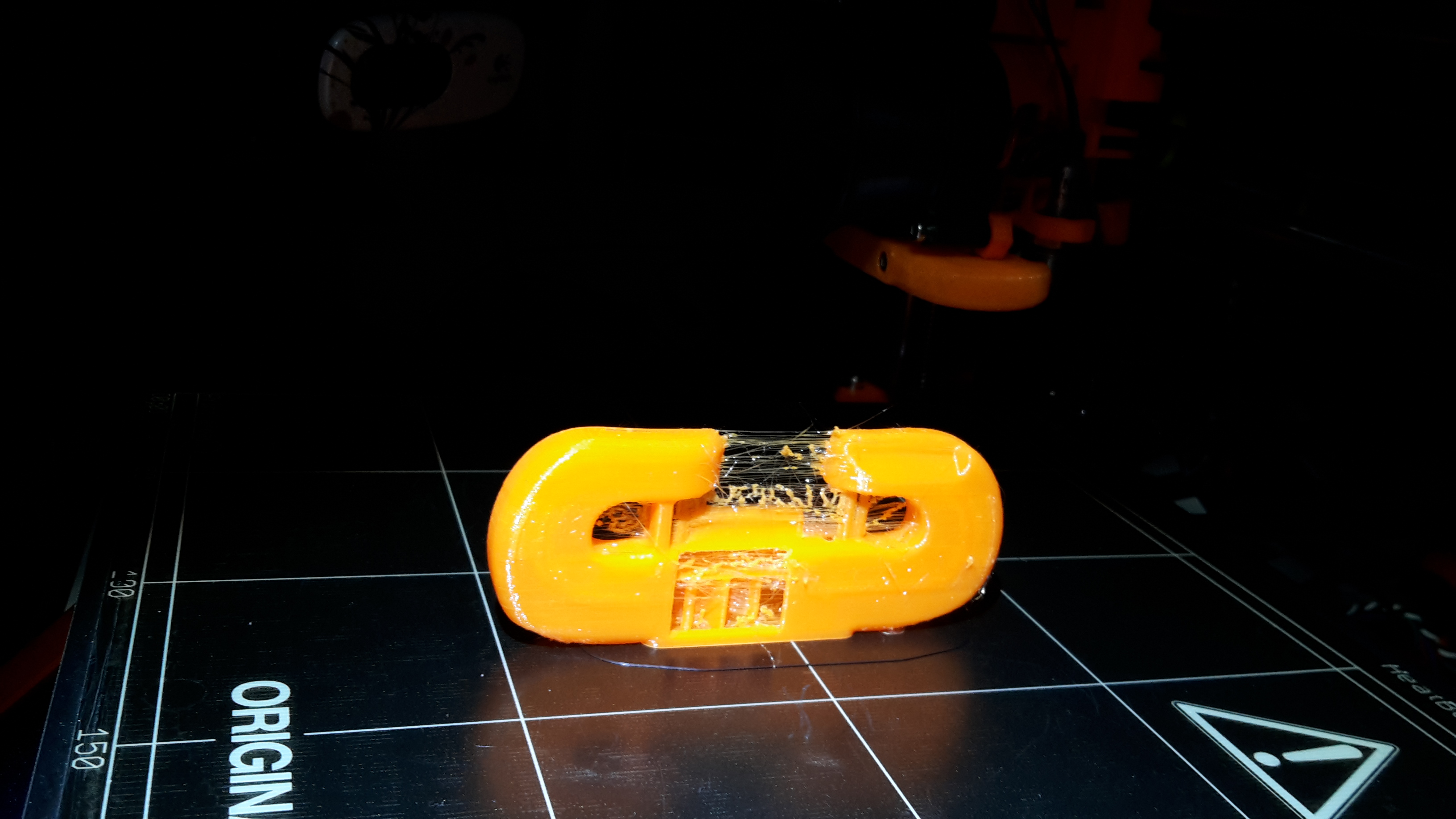
that doesn't look good, does it ?
dem inscheniör is' nix zu schwör...
Re: Improved fan shroud / nozzle
...
that doesn't look good, does it ?
Lol, i should have expected that that would be the picture you would show me. 😆
No it doesn't look good at all, It looks like your retraction is insufficient now for some reason which is not a problem I've had. I could imagine that if you have that retraction problem on the outside, then the inside might also be filled with junk that is in the air path.
Anyway, to check if the problem is with the combination of the duct and the sock, I'll print the latest design to check if it's just because I haven't had enough retractions to notice the problem.
I've updated the design in a V4 version to have the full surface against the build plate and start at a 45 degrees angle. Also, I've moved the openings a bit away from the hotend and increased their downwards slope slightly to point more towards the print.
I've also widened the openings so the "arms" are 12mm rather than 10mm wide as this is the most I can do without causing interference with the P.I.N.D.A probe. Widening the openings will reduce the air speed at the exit which reduces the print cooling efficientcy but also reduces any turbulence that might be near the hotend.


I can confidently say that the combination of a sock and the duct does not have a negative interaction effect as I don't have the retraction issues you see and the amount of stringing is the same as I've had in a long time with a retraction length of 1mm and a retraction speed of 35 mm/s at a print temperature of 210 degrees.
The problem seems to be on your end and not something I can manipulate from here with a change of design.
Re: Improved fan shroud / nozzle
....
I can confidently say that the combination of a sock and the duct does not have a negative interaction effect as I don't have the retraction issues you see and the amount of stringing is the same as I've had in a long time with a retraction length of 1mm and a retraction speed of 35 mm/s at a print temperature of 210 degrees.
The problem seems to be on your end and not something I can manipulate from here with a change of design.
ok, the (badly) printed duct was sliced with Simplify3D and my retraction settings were 0.8mm @ 25mm/s so far (as conclusion of the musing about retraction here).
but results are now better with slic3r default settings of 35mm/s for retraction.
guess that you are right and I've had bad settings at my slicer (S3D), because I changed a few values since linear advance was introduced, and the bad stringing just became evident as I coincidentally changed the duct (after printing Jakob's *.gcode, that he sliced with slic3r as well).
anyhow, your new design (with the 45° angle) looks as if it'll be a little bit easier to print.
guess you're going to load it up at your thingiverse thing...
dem inscheniör is' nix zu schwör...
Re: Improved fan shroud / nozzle
...
anyhow, your new design (with the 45° angle) looks as if it'll be a little bit easier to print.
guess you're going to load it up at your thingiverse thing...
Yep, I uploaded it now and with a few more support columns added as I had a bit of overhanging problems near the front outlet.
Here it is.
Good luck printing it. 😉
Re: Improved fan shroud / nozzle
Try this.
Don't know if I have taken enough off, and it is very rough...
Peter
I hope you don't mind but I'm going to toss this on Thingiverse. I'll give you credit in the description of the object. I'm only doing this because I've printed a ton of the variations of this shroud and this is the one that worked best for me.
Here is the thingiverse posting.
https://www.thingiverse.com/thing:2756449
I put the remix as the original shroud/duct mod just because he was the first. If you're not ok with any of this hit me up 🙂 This is a really great mod and my prints are coming out MUCH better because of it.
Re: Improved fan shroud / nozzle
..and my prints are coming out MUCH better because of it.
I'm not so sure about that. I've tested PJR's design, the stock design, and Sebastian's design back to back and see pretty bad results. On a full model the differences are very minimal (Sebastian's wins this albeit barely). However, on a 100mm bridge the stock shroud actually does a quite a bit better. I think PJR's smaller approach design is the key (air pressure), while using a scientific approach like in Sebastian's shroud is what will seal the deal.