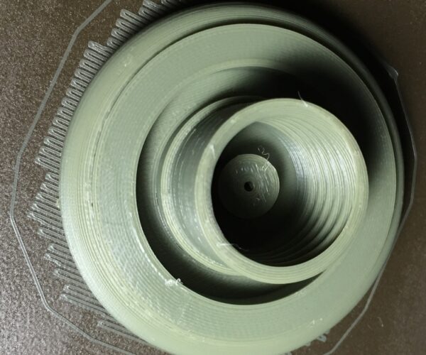
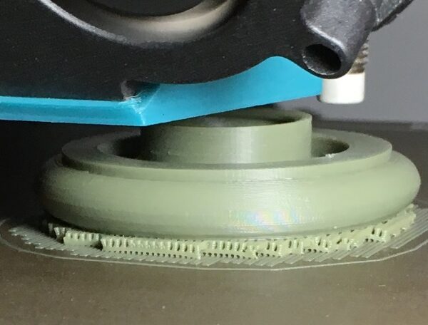
Very poor print quality on underside of ABS even with supports
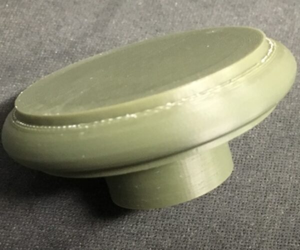
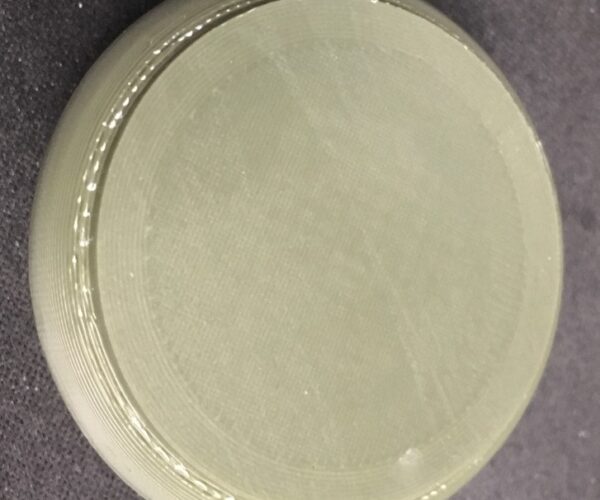
I changed from PLA to ABS for this part to get better impact resistance. I didn't want it to crack if dropped. I used Paramount 3D filament. Box says print temp is 220C-250C, Bed temp 100C-110C. Since the forum only allows upload of media files I've attached screen captures from slicer as well as some from fusion 36o to show the designed profile. Finally I attached pictures from the last attempt. Previous attempts were at 220, 230, 240C. I mostly used the bet at 100 for the 1st layer and 110C for all others. I did some variances on that but nothing helped. I don't use an enclosure but I don't have any drafts either. The bed stayed at the correct temperature throughout the print. Nothing I've done has helped the quality or shape of the bottom side of the curved surface, even with supports. Since I'm going to sand this to get a good finish, I'm ok with some defects caused by the supports but I need the profile curve to come close to the design. The part prints with an angled bottom and a very slight curve on top. Is there a way to use ABS for this part?
Best Answer by jrdpiper:
Because of all of the modifiers that swiss_cheese helped me with to get the original part to print correctly it took me a while to get the the new part (with recess in bottom) printing correctly. I added a new modifer which is a cylinder support enforcer. It is set to the size of the recess. Worked great. The supports came off cleanly. Attached is the new project file. The second cylinder object is the one I added.
Are you able to use soluble supports? (MMU?)
I agree that the bottom of some ABS (and PLA and PETg) prints done with detachable supports are 'butt ugly', for lack of a better term.
I've printed some model railroad flatcar beds using detachable supports, but those are normally displayed 'greasy side down' and it does not really matter.
Lately I've been doing the ABS prints that need supports on an Ultimaker with a dual extruder, and using soluble media and very close spacing between the support material and the main print.
@jimd
If you will Zip up and Post a .3mf project file I'll take a look, I print quite a bit of Paramount 3D ABS and I find it a pleasure to work with, from the look of your images at least, this model should pose no issues, I think it may just need some tuning.
The .3mf file must be zipped up to be posted on the forums, and just to be clear I don't need the .3mf exported from Fusion360. I need the .3mf project file exported from Prusa Slicer.
Good Luck
Swiss_Cheese
The Filament Whisperer
adding .3mf file
I zipped the .3mf from slicer and attached it.
adding .3mf file
I zipped the .3mf from slicer and attached it.
Simple object - doesn't need supports.
Turn off supports. That is a flat bottom object. The only thing I noticed is the part is positioned beneath the print bed in your file.
adding sliced view
Attached is the view after it was sliced. What was showing below the bed was the support. The object is flat but only about 1/16" high then it curves upward to match the top curve. Check out the pictures in the prusaforum.zip I attached in the original post. The two screen captures I did from Fusion 360 show the designed profile. I added the support when I was using PLA to get better results on the bottom curve. It helped a lot but with ABS not at all.
I'd get rid of those "supports"
This thing should print easily. No raft needed. There is no detail on the bottom of print at all (per your model file).
Another try (and fail) without supports
Thanks for the suggestion. I removed the supports and it didn't affect the print. I see in Slicer that the overhang portion was very small anyway. Attached are pictures of the bottom and top of the last print. I also included the .3mf file I used. The bottom of this part with abs show similar results regardless of temp of base or hotend. The top half is usable but the bottom half isn't even close to the right profile. PLA was a lot better but its characteristics related to impact rule it out for my purpose.
First layer is suspect for sure - but that's a whopper of an overhang
The initial overhang is going to be a wreck if you don't absolutely nail your settings. I'll try printing this in ABS this afternoon.
Does that profile have to be what it is? It's somewhat stylish, but definitely not in the spectrum of "designed for 3D printing". If you realize that things will start to get rough past 45 to 50 degrees of overhang, you would look at this part differently.
overhang and supports
The overhang was why I added the supports. As I said previously, the PLA version came out usable. I wonder if there is a way to have it generate supports all along the bottom curve. When I looked at the side view of the sliced model the cylindrical supports didn't come up to the full bottom curve. As for the shape, it needs to be close to this. This is the sole piece for a electronic musical instrument. The threaded part will form the negative contact for the battery. It mates with another model that holds the batteries. The shape would be recognizable to people familiar with the instrument.
As a plan B, it I can print with 100% infill, could make the horizontal piece a straight sided cylinder and then turn the profile on my lathe. No clue how ABS turns. I'm hoping to print as this is a lot of extra work.
What you added is not what I would consider support
Adding that cylinder threw me off until I checked it in PS and then deleted that. The profile settings were a bit off - so I'm adjusting them. I'll enable auto-generate support and set the separation distance to .25mm - the interface should not be too hard to separate in a finishing step. ABS is very stiff material - so getting the separation distance for supports dialed in is the bulk of this print. I'm also increasing perimeters to 3, so there is some better wall integrity. I have reset the temp settings to default for the generic ABS profile - I've had decent outcome with its default settings. I also reset the first layer height and layer height to the defaults for the layer height (.15 mm). For a battery door, I wouldn't think you need the precision to get the threads to work, but I'll give it a go at .15.
I will be able to start the print in about 30 minutes from now (12:30 PM PST). It'll take most of the afternoon at .15, but I want to see if my setting changes help get you dialed in better than grafting a cylinder onto the print....
@jimd
I'm working on a solution (Tuned your print settings), I'm going to test print before I post, I am using paramount 3d ABS, everything is printing fine sofar.
Relax, enjoy, I'll be back.
Regards
Swiss_Cheese
The Filament Whisperer
Paramount 3D (Military Green) ABS
@jimd
Try these settings, I did some tuning so you may not recognize some of the settings, however the part is quite strong I printed two and threw one at the cement trying to break it (of course I knew it wouldn't) but for good measure 😎.
They printed great, I decided to use support for the two layers that might have caused a problem, since it so easy to remove support from ABS it was never going to be an issue. if for some reason the tiny marks are bothering you, you can make then disappear with a tiny paint brush or a Q-tip and Acetone (tiny brush works best) it's more precise.
There's a lot to learn in the .3mf so be sure to poke around in it.
Good Luck, Have fun.
Swiss_Cheese
The Filament Whisperer
Important !
@jimd
I forgot to mention, and this is important, when you open the .3mf in slicer and it asks if you want to enable "Detect Bridging perimeters" Select (NO)
Regards
Swiss_Cheese
The Filament Whisperer
Beat me to it
I was about to start print #3 - dialing in one setting at a time.
The more the merrier
@dan-rogers
It's up to you, but I'd go ahead and post, you have shown some nice prints. also your result or method could be more desirable to the OP.
I specifically told the OP I would take a look and I wanted to follow through.
It's all good,
Swiss_Cheese
The Filament Whisperer
I'm trying to understand your file ...
I have only recently run into the concept of modifiers - is that what you used here? Is there a good overview of the click sequence used to create a modifier online here? Some understanding of why you added those layer and perimeter sets as you did would be wonderful walk through.
I have taken a slightly different approach - I noticed that the dense infill settings were causing the ABS to overheat and start melting during the print, so I reduced the infill density and changed it to gyroid - with only one of those battery covers on the print bed, the heat is building up too much in the print due to the dense infill. I also noticed that changing to .2mm layer height caused the threads to start failing due to the overhangs there - and I noticed you added a modifier over that part of the print as well - will dig into what you did there.
Generally, I know better than to try and print a shape like this - but it is good to learn that it is possible to overcome these types of overhangs. Circular profiles are hard to print 😉
For Dan
@dan-rogers
I'll try to explain some about the modifiers, but first just want to mention you are absolutely correct about the solid infill, the to much heat to much plastic, the model shape, and your correct about the layer heights, you might also have noticed that at one point the OP had a layer height of 0.1 set with 100% infill (that was never going to work) well, it could, but it would be a ridiculously long unnecessary print.
My point is your recognizing the problems, you know why it failed. The way to fix it is to tune the model, but if we try to apply only one or two changed parameters to the entire model it will fail in different ways (areas), for example, choosing to use 0.2 layer heights works great at the bottom but not so much for the threaded area, this is where modifiers come in, using (MM) (Modifier Meshes) and (HRM) (Height Range Modifiers) (and several other tools in slicer) you can pin point and adjust certain areas, give them their own properties you can change the layer height, extrusion width, etc,etc, of just 1 layer 15 layers or even a portion of a layer (whatever is needed) you have the tools in slicer to take full control. If I'm being honest slicer is still coming into it's own, I have had to develop a lot of work around's to get the results I want, but so what, they (good results) can be had.
I'll start at the bottom and work my way up. like you I went through the OP's .3mf and In areas where I recognized issues I made changes, kind of a rough first pass, I can normally get it pretty good first try but this shows you what you might have missed, in this case my first draft showed me that I was going to have a curling issue on the edges since I was printing outside of an enclosure and it showed a conflict that I had when applying one of the modifiers I used.
So in the final I added 10 perimeters using a (HRM) to what would have been the bottom solid layers, no extra plastic used but the 10 perimeters on a round shape like this will tend to have a better chance of success (curl less). Next I needed to tackle that overhang, two of the perimeters are overhanging 90 degrees unsupported with no chance of being supported by wider extrusion this means using supports PS gives us a nice tool for this in the form of the "Paint-on support" tool, however even though it's called the paint-on support tool it has another feature, "Autoset by angle" and you can literally set supports to an individual strand of filament, so I selected the two offending perimeters and added support (Defaults because ABS is awesome).
Next, you may have noticed in slicer there was a bunch of purple stuff trying to ensure the shell thickness in the OP's .3mf, it's not to much plastic but its back and forth application is counter productive, in this case, so using a (HRM) I chose to apply this plastic in the form of extra parameters, the hot end spends less time applying it, hence less heat in an already struggling area with faster cooling, great strength benefits shorter print times, and lets be honest, it looks cleaner too. In this same height range I also removed all Bottom layers since this is what slicer saw being needed in this area by default.
(Meanwhile) everything I'm trying to fix on the outside of the model is also happening to the inside (The Threaded area) and we don't want this. when you use Height Range modifiers, they effect everything that pertains to the "specified parameters" in that height range e.g. you set the "extrusion width" it will change the extrusion width on every feature in that layer range. In this case I used a (MM), the cylinder you see in the center of the model in my version of the .3mf, to add back in several of the features I removed or changed when I applied the (HRM) to the outer area of the model, when using Modifier Meshes all the changes are made within the volume of the Modifier Mesh, so placement and size are important, Note: Mesh modifiers and height range do not always play well with each other, there can be conflicts. Hierarchy must be learned and respected, it should also be noted that there are some hierarchy changes in the up and coming PS 2.4 (keep that in mind as you learn modifiers)
Using the (MM) I added back the top & bottom layers, changed the Perimeter width for the threaded area (to much plastic in that area), and changed the perimeter amount to remove excessive top and bottom fill in the threads themselves, I also changed the top infill pattern back to Monotonic since one of the (HRM) I used to apply a Concentric Top fill pattern was conflicting with my (MM).
Modifiers are very powerful they can allow you to do things that you would struggle with trying to just type it out in g code, because it's visual, you have a reference, you can really put that plastic where and how you want it. Some parameters can overlap just fine between (HRM) and (MM) some can't. These things aren't well documented and just like the Concentric Top fill pattern for example, you will see posts all the time from folks who don't really understand how to use them complaining that they don't work. So Play, learn, & have fun.
Anyway I hope this helps, I tried to keep this short
Good Luck
Swiss_Cheese
The Filament Whisperer
Thank you so much!
I appreciate your answer tremendously. Thanks man.


