Looking for help with a repeated print issue
Hello,
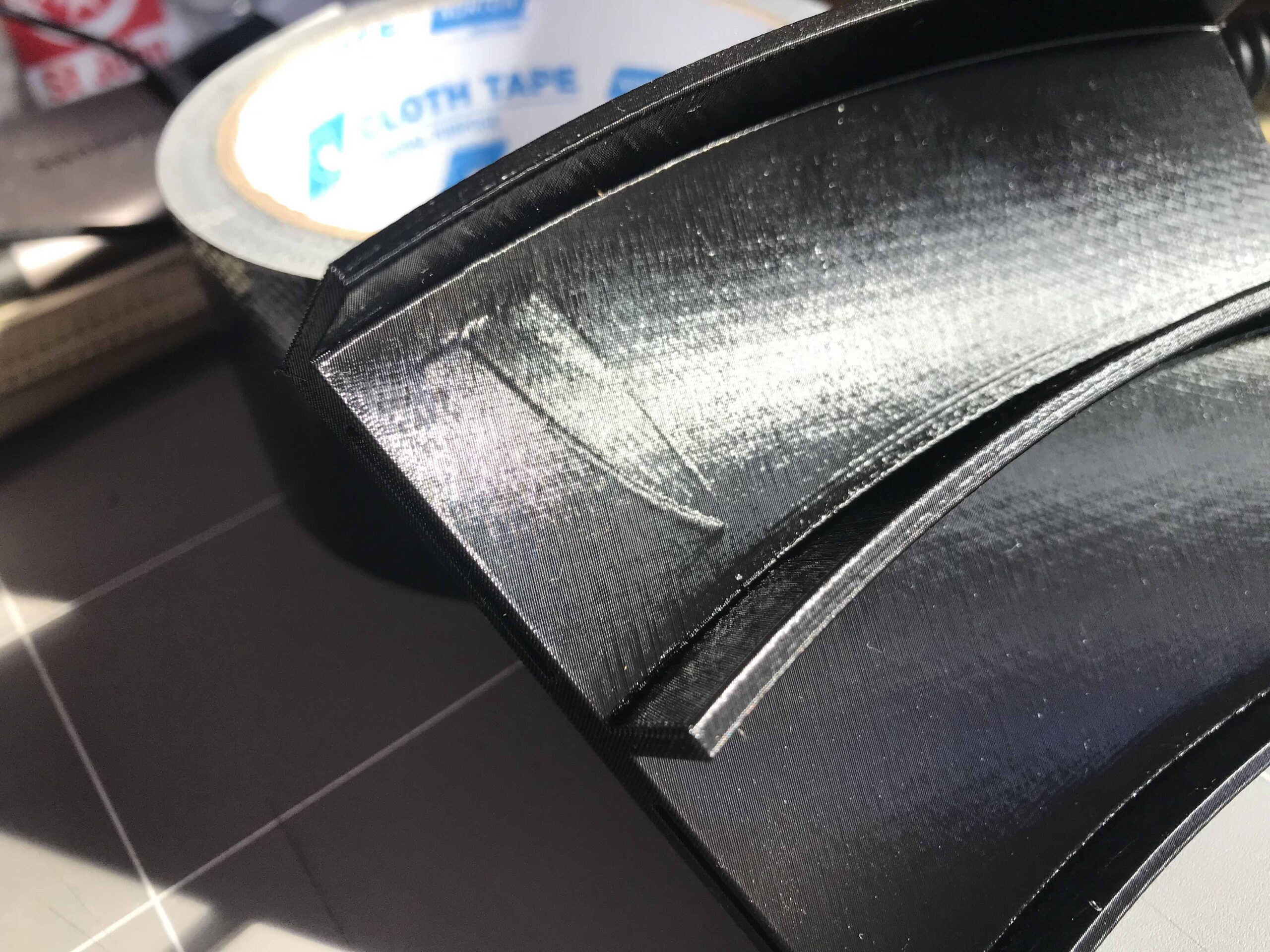
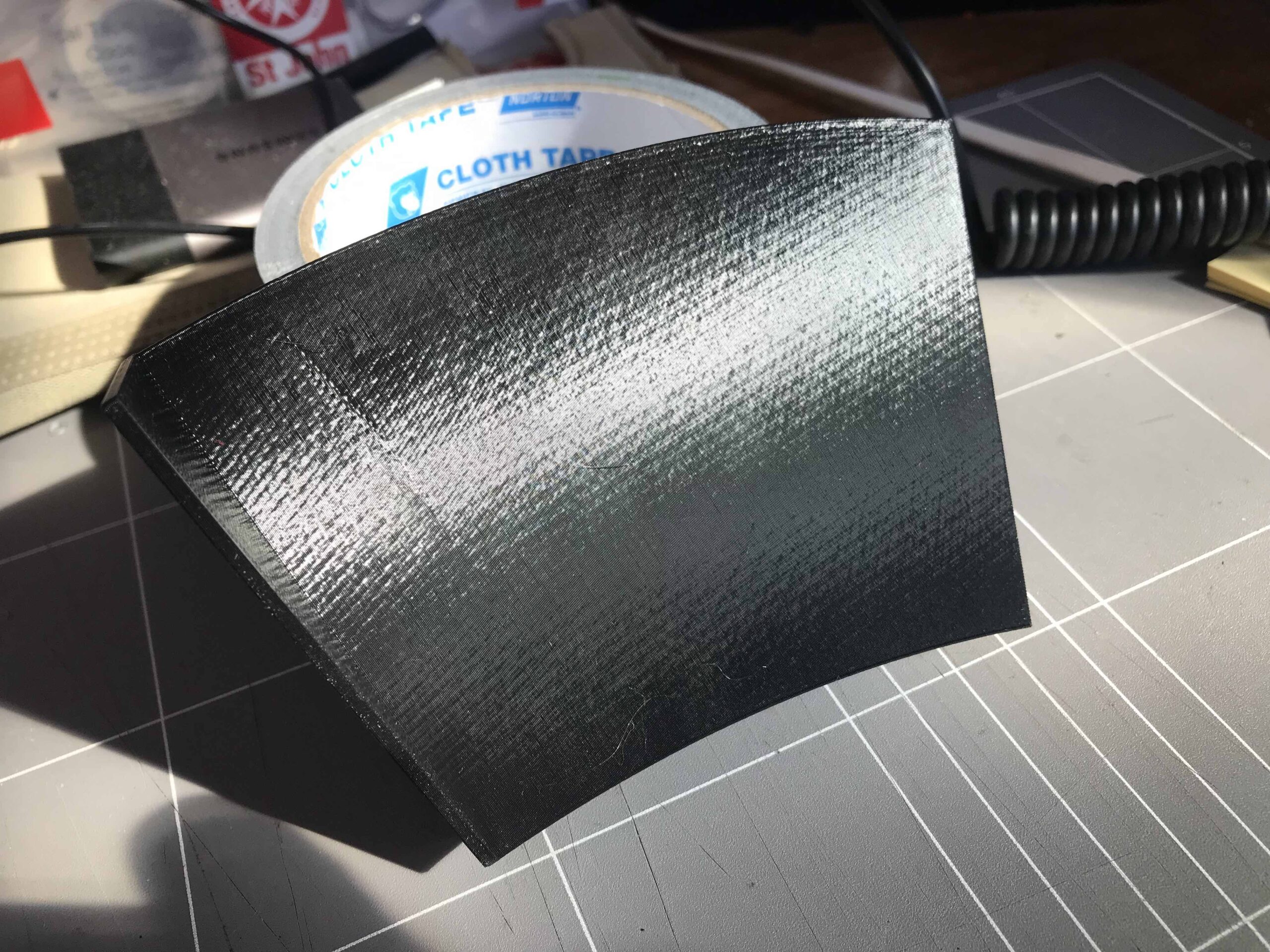
I have three MK3 printers which work very well on all prints other than this item I'm trying to print. This is a two lane 180deg race track for a Hot Wheels setup. I designed this in Fusion and used Prusa Slicer. The issue I'm having is where the connectors go in both top and bottom I'm noticing when the prints are complete that there's some odd markings on the top layer that I can't seem to remove. On the backside of the print everything looks fine.
EDIT: I looks like there's collapse from the top layer or the fill under the top layer is not sitting up correctly.
I have tried the following.
0.2 quality, stock setting
0.2 speed, stock setting
0.2 speed, 20% infill, 3 perimeters, GRID
0.2 quality, 15% infill, 3 perimeters. , Rectilinear
0.2 quality 0% infill, 3 perimeters.
All the above produce the same results.
Now I have rebuilt the design in Fusion thinking it was a STL issue and found no problems with this.
Can anyone advise a solution for this, I would love to here your thoughts.
RE: Bridging can be tricky
[...] I looks like there's collapse from the top layer or the fill under the top layer is not sitting up correctly.
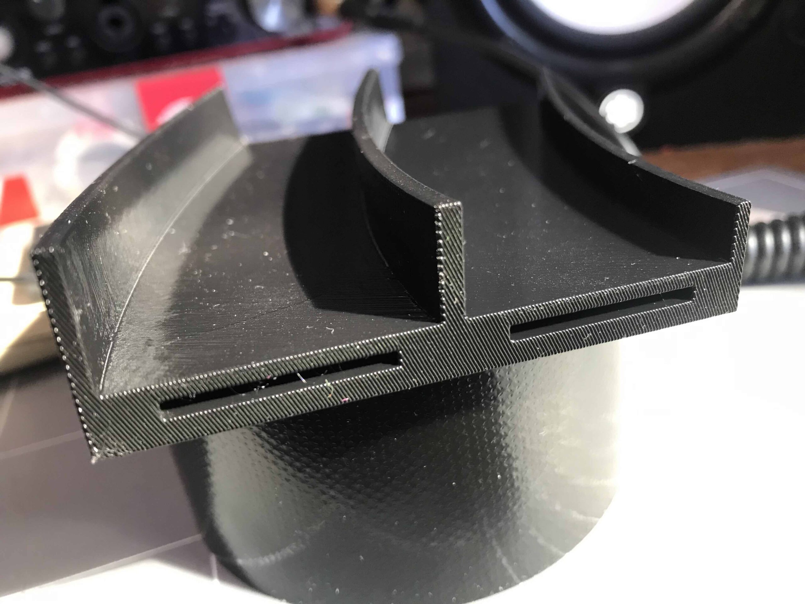
If I'm understanding correctly, it's the tops of the slots that are sagging, correct? That's a common problem with bridging where spans are literally printed in mid-air with no underlying support. Those slots are likely impossible to print support in. You can work with a number of bridging-related parameters. A lower layer height can sometimes help. The new 2.4 PrusaSlicer release also has additional bridging options that you might check out (though it's still in alpha).
If this is your design, it might be best to model in sacrificial supports. If this is somebody else's design, you might check in with the designer for recommendations. An ugly solution might be to print it vertically, but a lot depends on specific geometry and settings. Save your current 3MF project file, zip it up, and attach it to a reply here so we can see your part & settings and give better recommendations.
I just realized you're the designer. Do the bottom of those slots have to be closed? If not, you can leave a gap to the bed to allow printing of removable supports.
Hard to interpret picture
I just realized you printed this in a non-obvious orientation. Definitely upload that 3MF project file if you can, even just with a sample part for testing.
Do you require this 3MF from Pursa Slicer?
Thanks for getting back, this is my design and I do print this vertically, I'm assuming as there's a lot of angles going on the layers are struggling as you have mention. Do you require this 3MF from Pursa Slicer?
I printed this in a vertical orientation, the pice has a base which is not shown in the photos.
I printed this in a vertical orientation, the pice has a base which is not shown in the photos.
RE: Here is the 3MF file
Here is the 3MF file for you to look at.
For some reason it won't let me upload the file?
RE: Ok, here is the file attached
I have attached the 3mf file to this post, thanks again
Re trying to upload the 3mf file
Re trying to upload the 3mf file
Must upload in zip format
Re trying to upload the 3mf file
You have to zip it up first. The forum software will only accept some formats, including zip archives. Save your current 3MF project file, zip it up, and attach it to a reply here so we can see your part & settings and give better recommendations.
It's annoying, sorry.
Ah, that's why, I'll do this now.
Ah, that's why, I'll do this now.
3mf zip file attached
3mf zip file attached
@othila
This is where your problem is, it's caused by the forced intersection of the "External perimeter" & "perimeter" you have not left enough room between the outer wall and the pocket wall.
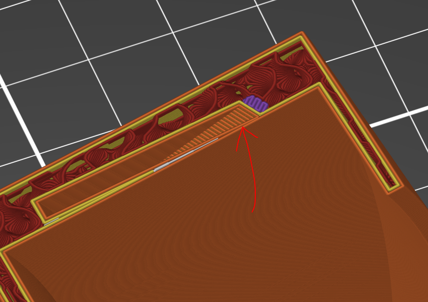
(The arrow shows the offending feature, avoid this scenario.)
You will notice that the pocket of the lower area and the outer wall are not having this issue,
the spacing is minimal but proper.
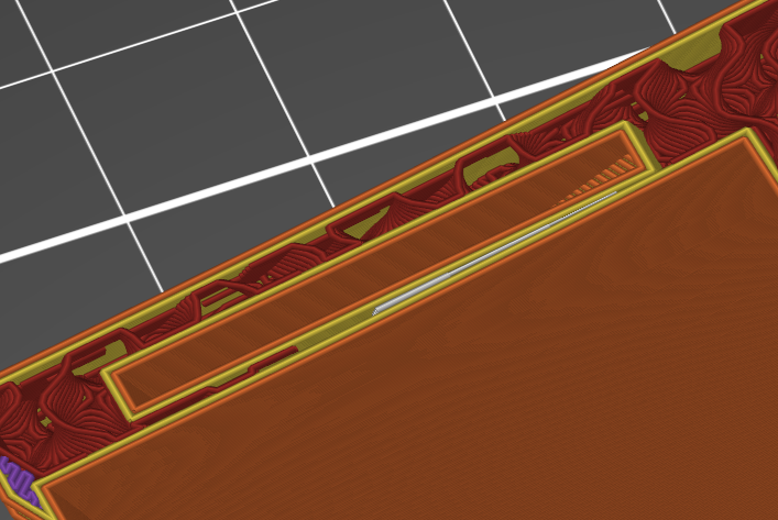
(This image shows minimal, however proper spacing.)
Make an attempt to redesign the area with a proper two perimeter gap allowing for a total of 4 perimeters of space at a minimum as the lower pocket has, and you should see your issue disappear.
Good Luck
Swiss_Cheese
The Filament Whisperer
Ok, that's interesting
Ok, that's interesting it is starting at the top of the print, I'll have a look and see what I can do. Thanks for your time.
your welcome, and please let us know how it turns out, or if you need anymore help.
very nice looking print btw.
Swiss_Cheese
The Filament Whisperer
I can now see where the issue is.
I can now see where the issue is, I was looking there myself however not in that area. I'll go back to my design and have look as this must be where it's starting from. Once again thanks for your help and I will come back with the results. Cheers
Why have the slots at all
I'm assuming you put wedges into the slots to join the parts - or the parts have wedges built into the end that lets them fit together easily. Why the square slots? Why not a simple round alignment hole - think a couple of pieces of filament as guides and locks. Glad you found the design flaw that causes your blemish.
Thanks Dan
Thanks Dan, I haven't totally found the issue yet as I'm working through this. When you join track pieces they are typical rectangle so it fits with other track pieces, this way everything is common.
That's what I figured
The size of that "fitting" square is enormous. Unless you need to make your track wedge into store bought track, I'm suggesting simply redesigning these to be much smaller than they are - it is the intersection between the wedge and your track walls that seems to be the issue. If if were me - and I was not going to sell these, I'd call it done and go play with hotwheels.
Yes the holes are massive
Yes the holes are massive and unfortunately that's how you connect to hot wheels track, not much can been done with this.
connectors
Dan, they take a little connactor like this:
https://www.thingiverse.com/thing:2883189
The come in different flavors but they are all essentially like this one.
The size of that "fitting" square is enormous. Unless you need to make your track wedge into store bought track, I'm suggesting simply redesigning these to be much smaller than they are - it is the intersection between the wedge and your track walls that seems to be the issue. If if were me - and I was not going to sell these, I'd call it done and go play with hotwheels.
--------------------
Chuck H
3D Printer Review Blog