Calibration cube first layers problem
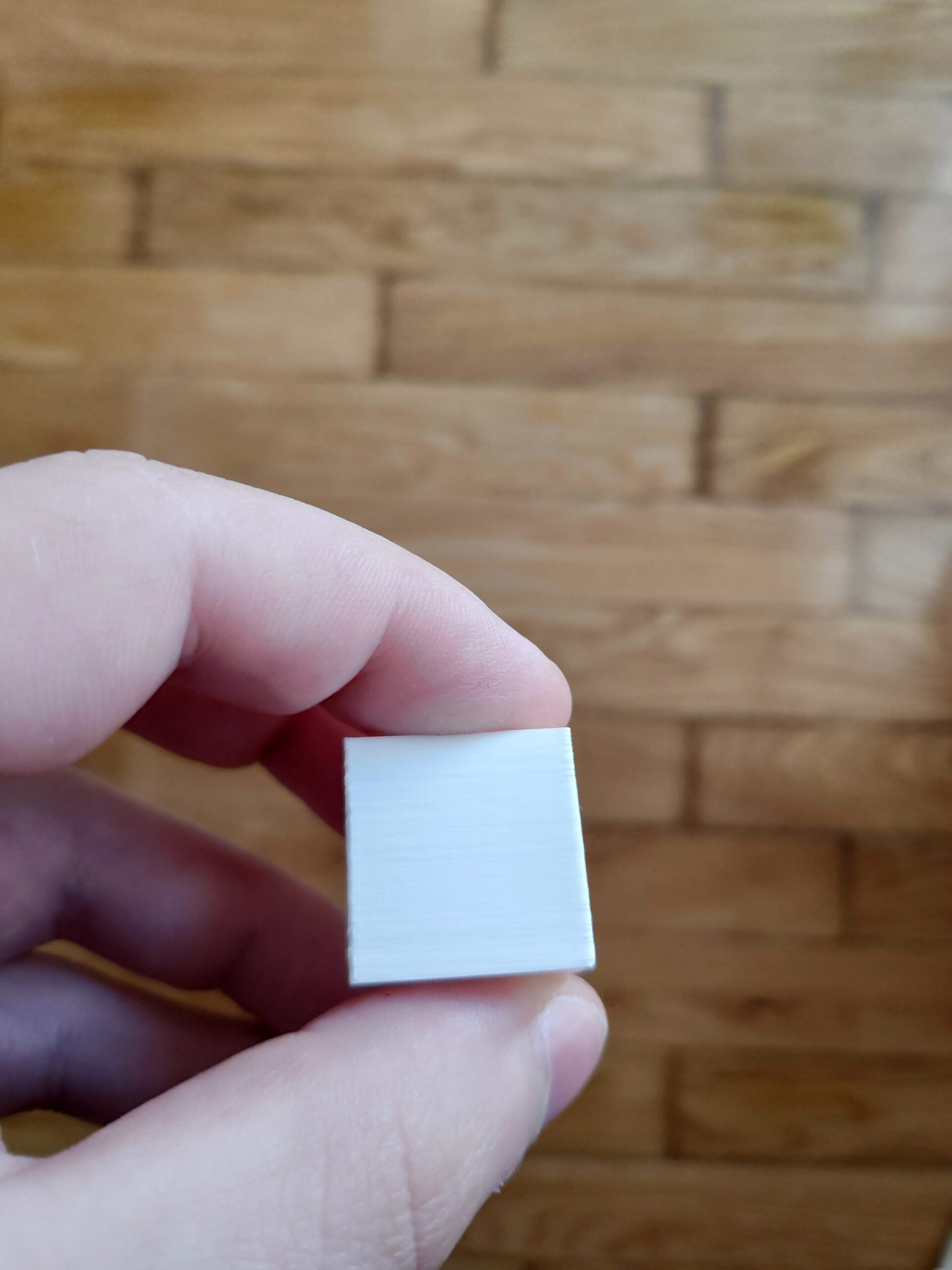
 As you can see in the pictures the first layers of the calibration cube are not aligned properly with the other ones.
- It's like they are smaller(to the center of the cube). I have this problem on all four sides of the cube. I used the default settings and i printed on petg and pla just to see if the problem was filament based and it's not.

 As you can see in the pictures the first layers of the calibration cube are not aligned properly with the other ones.
Best Answer by Tim Weston:
Here's how mine turned out (pretty much as I expected):
The vertical edges have two characteristics:
1. A slight bulge caused by slight over extrusion as the extruder changes direction by 90 degrees at the corner. This is pretty usual and very hard to eliminate.
2. Some small pips on the vertical edges that correspond to the seam positions. You can see those in PrusaSlicer by turning them on in the Show Options box at the bottom of the Plater tab. They look like this:

The letters have well defined edges with no obvious problems and sides are regular with no layer issues to speak of. Note: The brown bit is some burnt filament - time for a cold pull I think.
If you are seeing less smooth sides with clear differences at particular heights then start by checking that the screws of the X and Y motor pulleys are tight. In particular make sure that one is tightened properly against the flat section of the motor shaft. Next check your belt tension. I had this problem a little while back - it does not take much play for a defect to become visible!
Hopefully that gives you some pointers.
Cheers,
Tim
RE: Calibration cube first layers problem
Aaa it seems that the sliced file produces this effect as you can see in the picture below.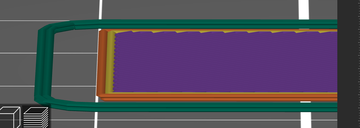
The thing is that in the 3d editor view the cube seems how it is supposed to be and not that way. So is there a problem with the slicer?
RE: Calibration cube first layers problem
If I read your post correctly, you are saying that the first layer is smaller on all four edges than the layers above. This looks like 'elephant's foot' compensation that is being applied by PrusSlicer. For info on that, see the article here: https://help.prusa3d.com/article/elephant-foot-compensation_114487 . Note: You need to be in Expert mode to see the setting. Default value for a Prusa-made profile is 0.2(mm) for a 0.4mm nozzle.
Hope that helps!
Cheers,
Tim
RE: Calibration cube first layers problem
Ok, thank you very much. Does this has to do with the first layer calibration. I mean, if it is perfect could i turn this setting off?
RE: Calibration cube first layers problem
The elephant's foot compensation is designed to counteract the tendency of the first layer to be a little over-squished (intentionally to ensure good adhesion) but the feature assumes you have an optimal first layer.
If your first layer is not printing low enough, then you will not be squishing the filament as much and the 'ele-foot' compensation will therefore tend to make the layer under-sized instead if correcting it to (more or less) the right size.
Hard to see from your pics how the first layer looks, but it is probably worth checking your Z-offset. I can recommend this print from 'fuchsr' to help you do that. The notes and links in the description will help you.
By all means post pictures (topside and underside) of a first layer calibration if you need more advice.
Cheers,
Tim
RE: Calibration cube first layers problem
So now that the size of the first layer is smaller than the rest means that i print too low, right? So my value for the z-offset is very low.
RE: Calibration cube first layers problem
Oh no it's the opposite!! So i need to go lower! NOW i believe i have it understand it correctly 😊
RE: Calibration cube first layers problem
Correct! If you are not printing low enough, the first layer is not squished down as much as it could/should be, but the compensation is still applied thus making the layer smaller by over-compensating.
I definitely recommend using that test print to have a play around with your Z-offset to really see if you are at the optimal value (which is particular to your printer setup).
It is also quite common that people don't set the Z-offset low enough!
Feel free to post some pictures of the calibration print if you wish and I will try to advise.
Cheers,
Tim
RE: Calibration cube first layers problem
Thank you veeeery much Tim!! Much appreciated. I will definitely try that stl file for the first layer calibration.
RE: Calibration cube first layers problem
No problem! Always happy to share knowledge.
Cheers,
Tim
RE: Calibration cube first layers problem
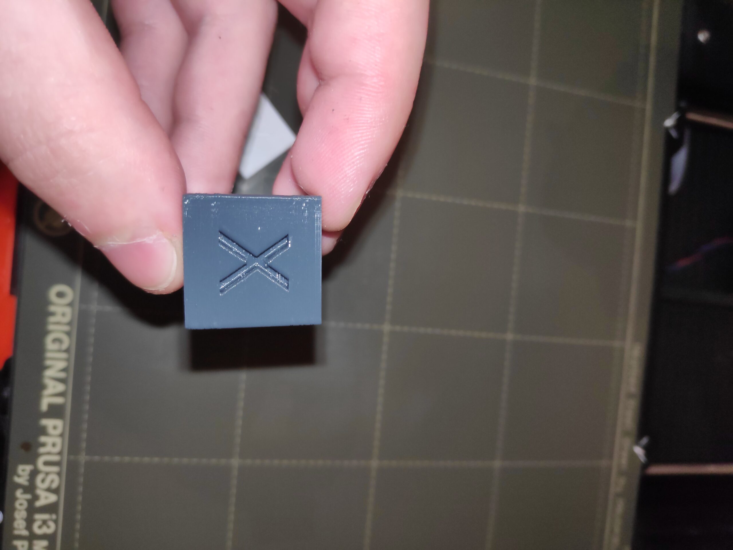
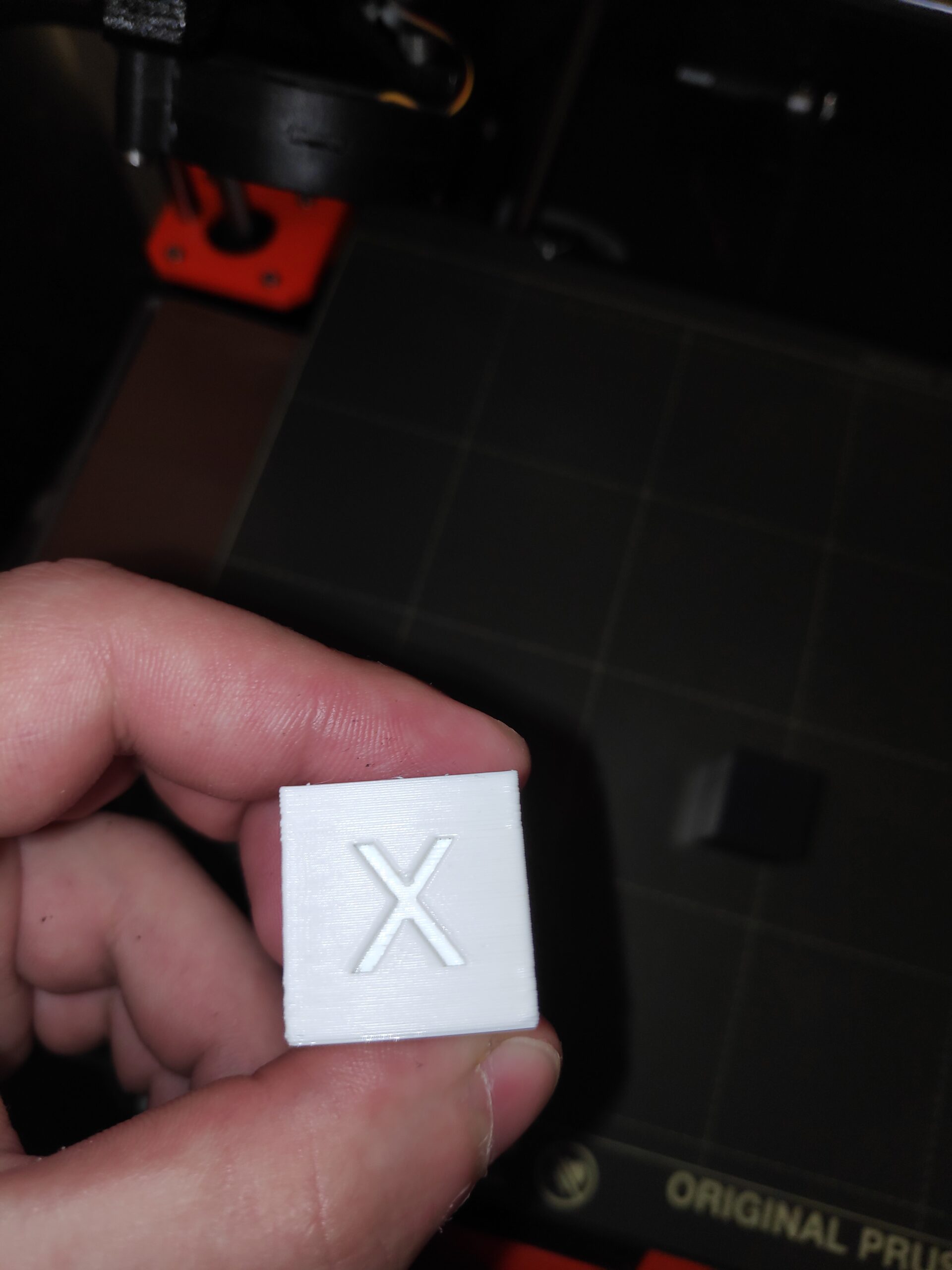
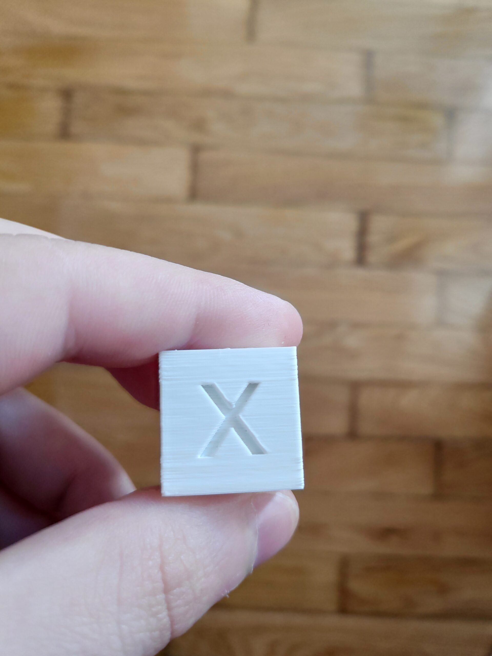
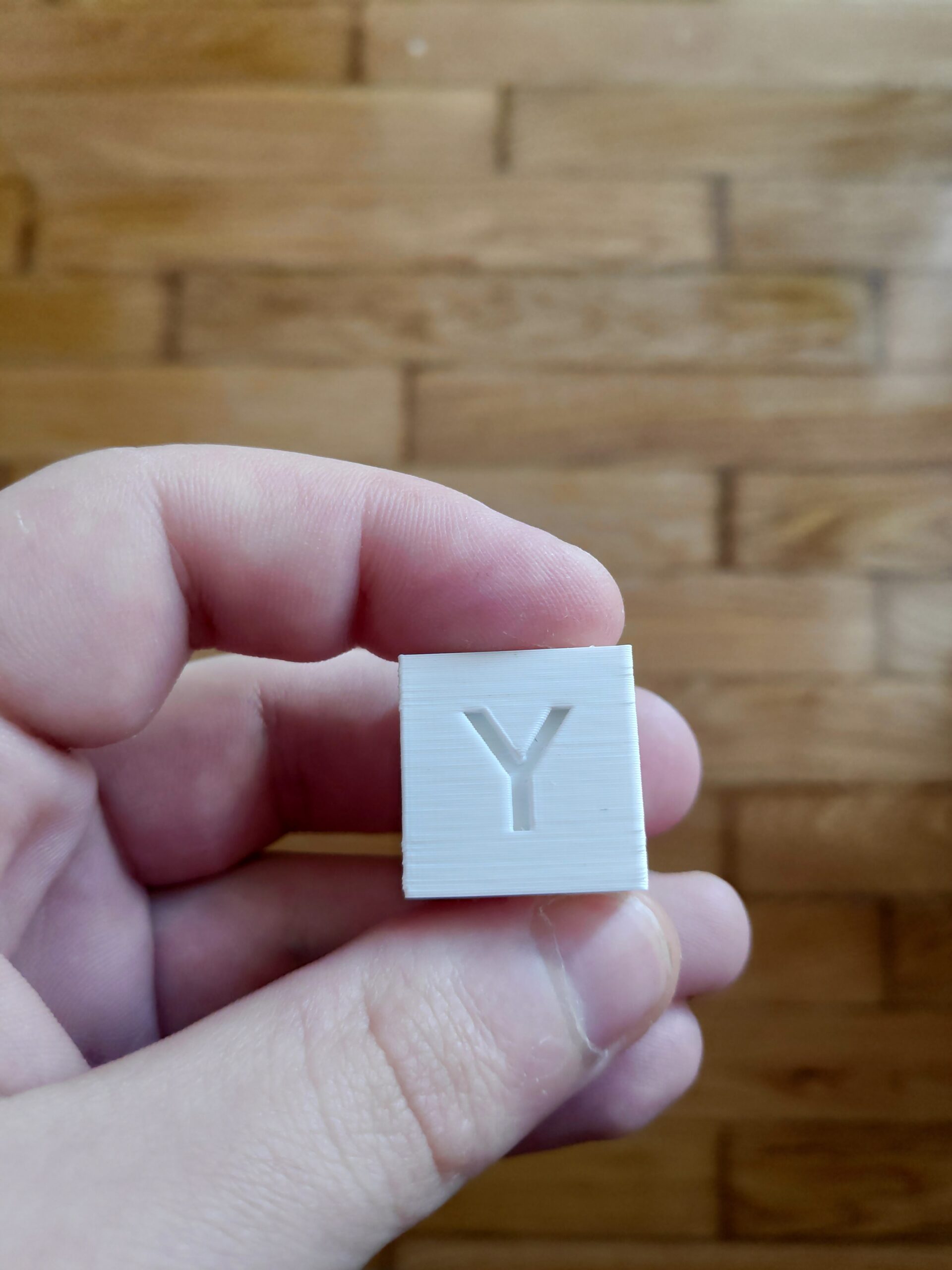
Here is my new calibration cube. All settings are on default. The layers seem inconsistent and what are those things on the edges of the cube. Are those the seams? 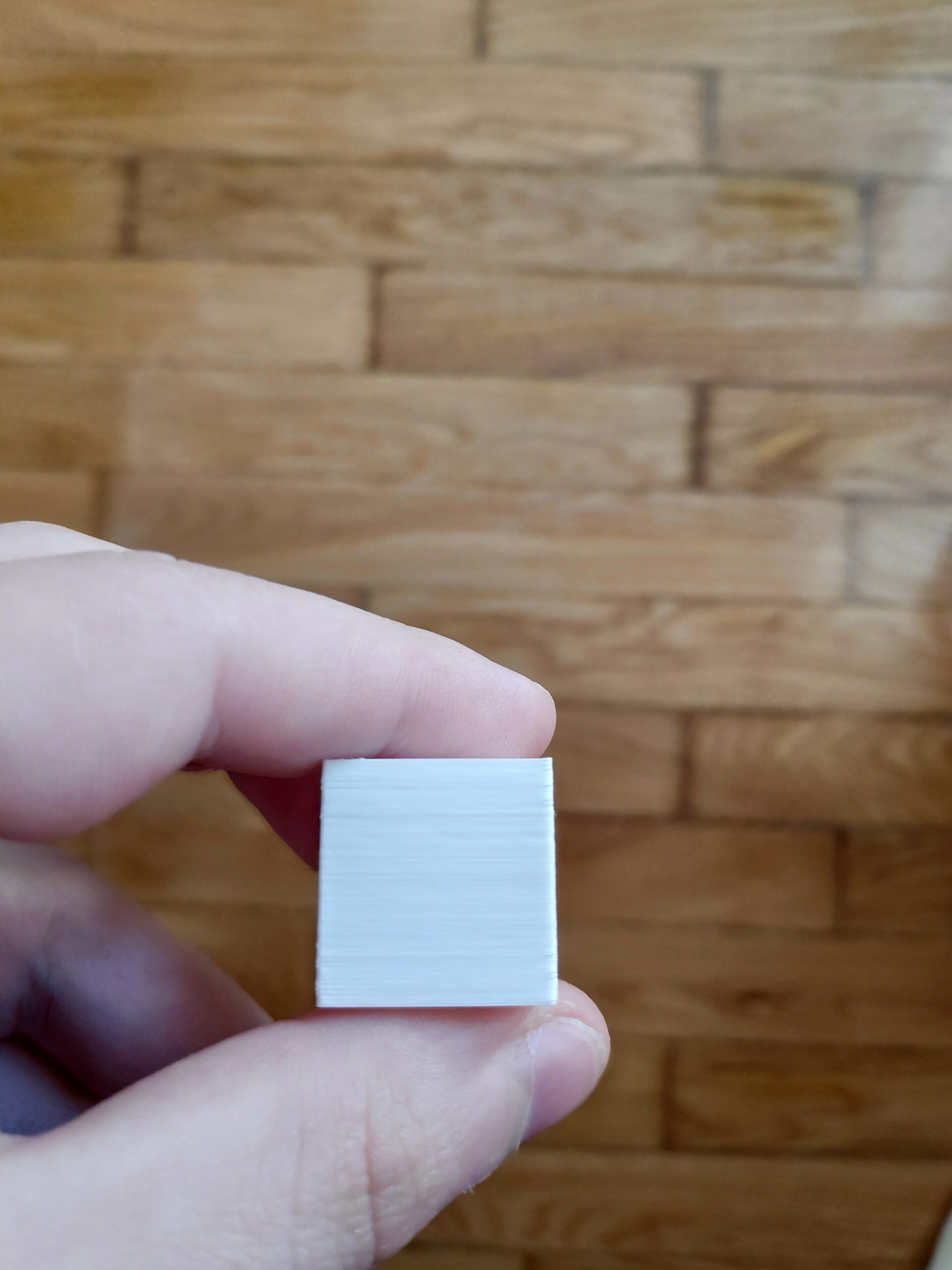
RE: Calibration cube first layers problem
Hard to see from the pictures and also the text in your post was truncated at the end. Is it possible for you to post some close-up images so I can get a better look.
The nibs on the corners may be the seams. Either that or you have some minor layer shifting going on. A better picture would really help.
Cheers,
Tim
RE: Calibration cube first layers problem
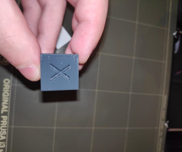
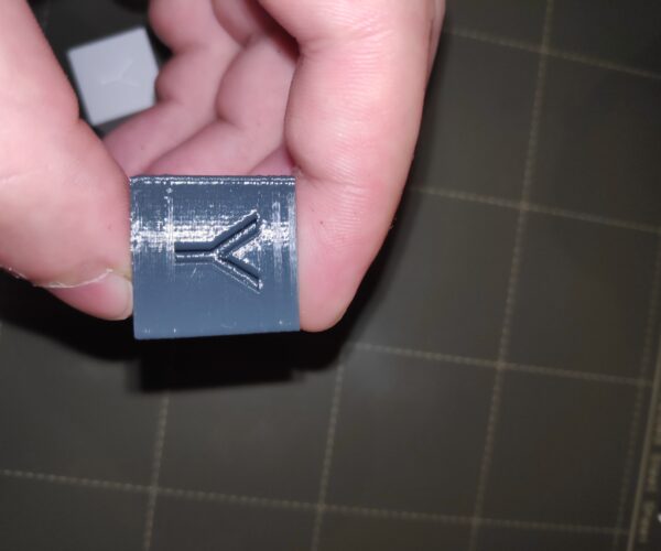
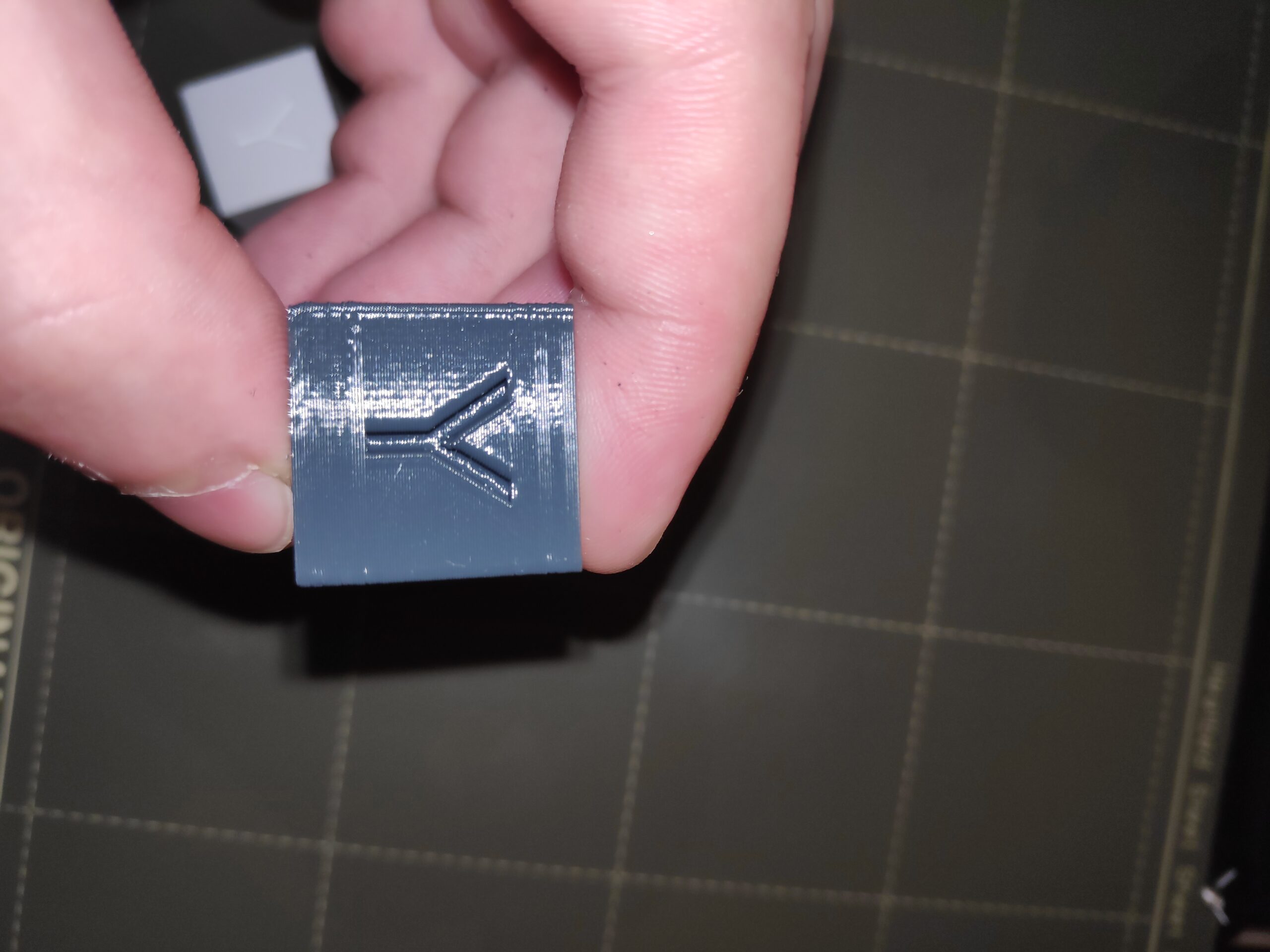
Unfortunately no. This is the best i can do with my phone. There are some visible lines on the "x" and "y". What are those? The thing is that the old cubes don't have that and the only thing i changed is the live adjust z.
RE: Calibration cube first layers problem
Thought that might be the case!
Can you please post a zipped version of the .3mf file for the cube that you can save from PrusaSlicer. You need to zip it because the forum does not allow unzipped .3mf files to be added.
Based on looking at that I may have some more suggestions.
Cheers,
Tim
RE: Calibration cube first layers problem
It is this cube. Settings are on default.
RE: Calibration cube first layers problem
Understand, but for the avoidance of doubt it will be far better if you post the .3mf saved from your PrusaSlicer instance, as that is what is actually generating the G-code.
RE: Calibration cube first layers problem
Ok, here it is.
RE: Calibration cube first layers problem
Thanks. I'll print one here in Orange PETG and see what I get. Catch you later.
Cheers,
Tim
RE: Calibration cube first layers problem
Ok, thanks Tim.
RE: Calibration cube first layers problem
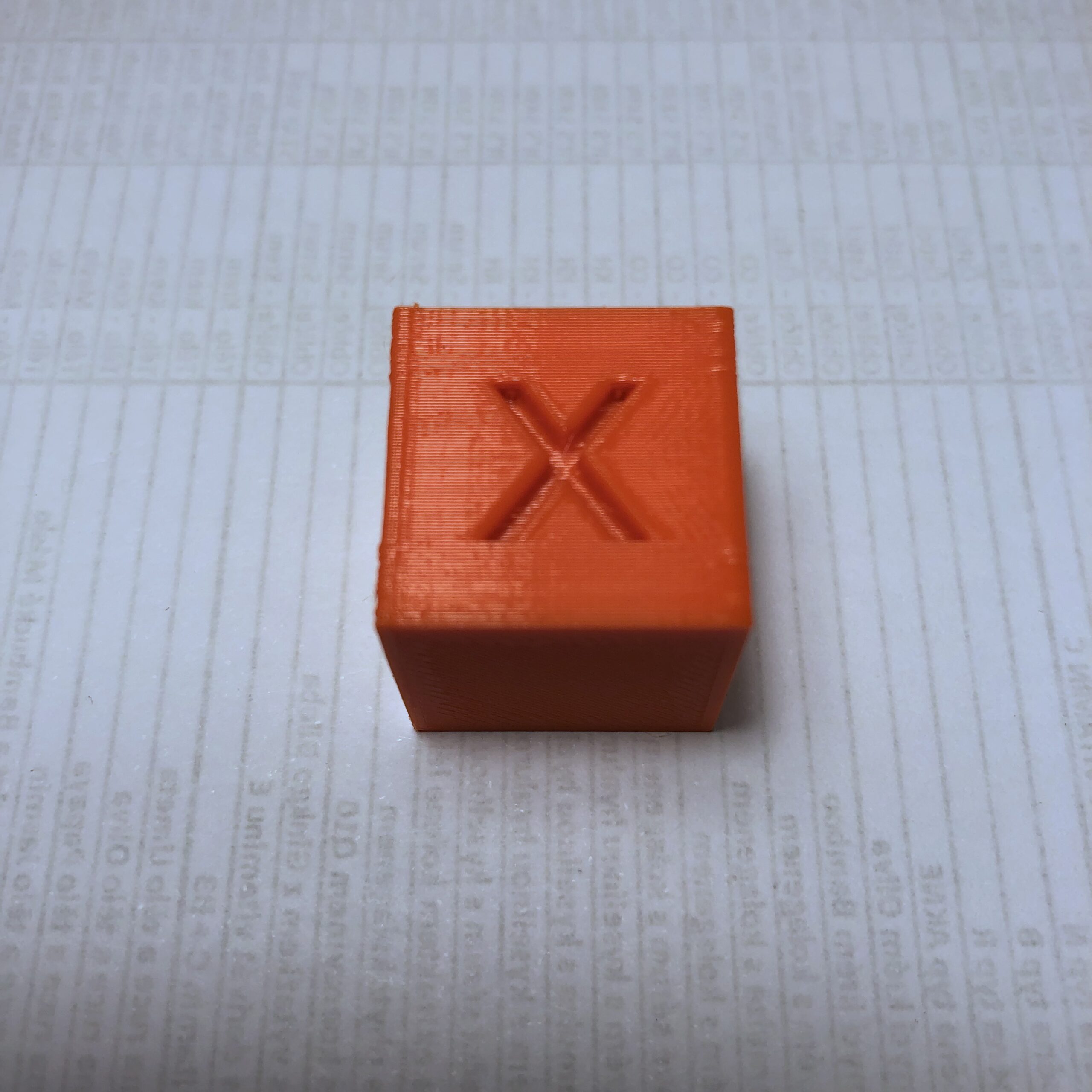
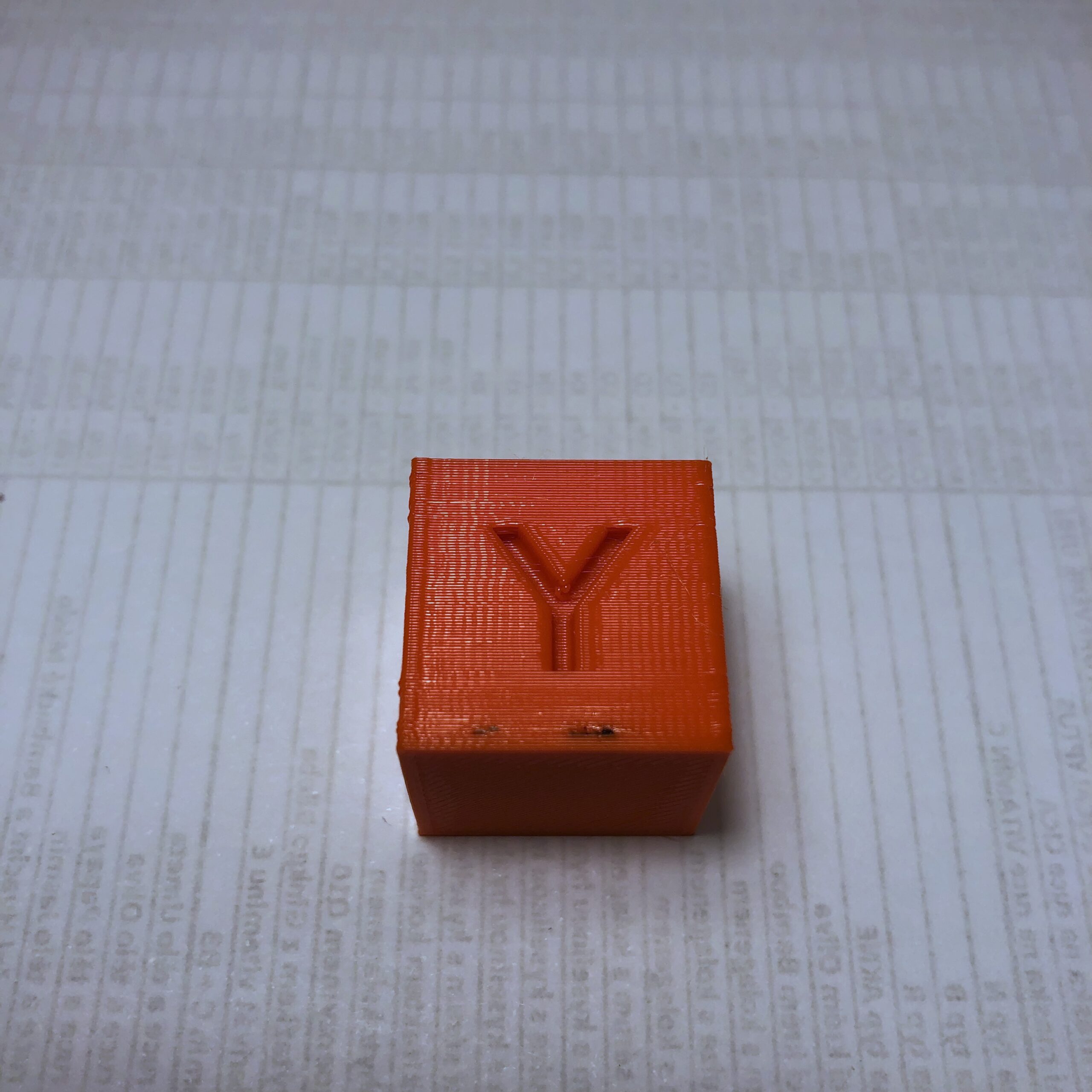
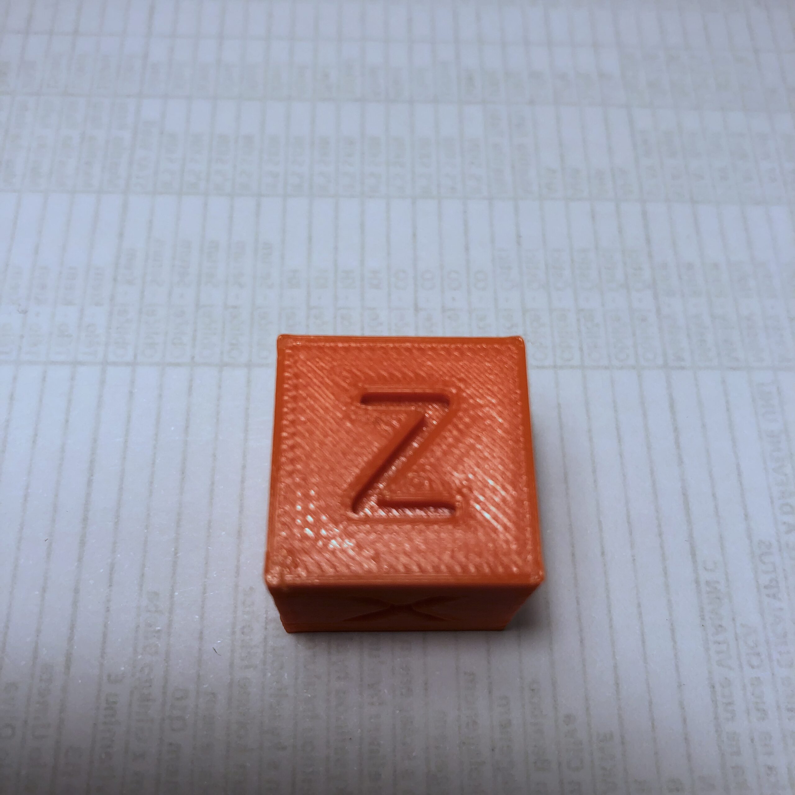
Here's how mine turned out (pretty much as I expected):
The vertical edges have two characteristics:
1. A slight bulge caused by slight over extrusion as the extruder changes direction by 90 degrees at the corner. This is pretty usual and very hard to eliminate.
2. Some small pips on the vertical edges that correspond to the seam positions. You can see those in PrusaSlicer by turning them on in the Show Options box at the bottom of the Plater tab. They look like this:
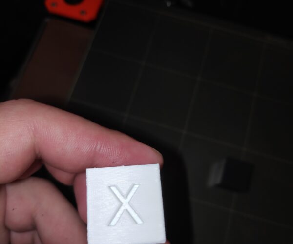
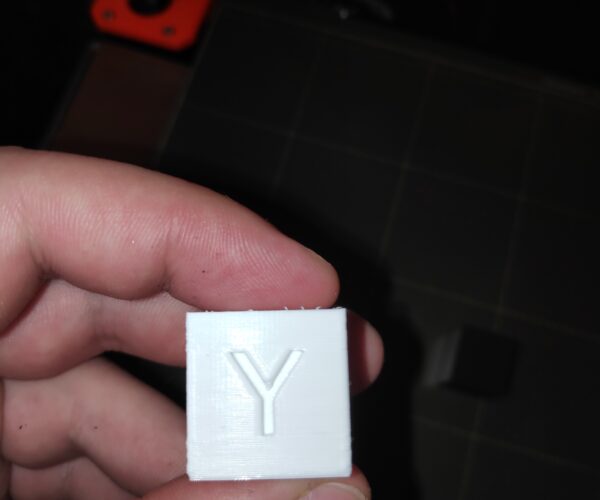
The letters have well defined edges with no obvious problems and sides are regular with no layer issues to speak of. Note: The brown bit is some burnt filament - time for a cold pull I think.
If you are seeing less smooth sides with clear differences at particular heights then start by checking that the screws of the X and Y motor pulleys are tight. In particular make sure that one is tightened properly against the flat section of the motor shaft. Next check your belt tension. I had this problem a little while back - it does not take much play for a defect to become visible!
Hopefully that gives you some pointers.
Cheers,
Tim