Re: Buldge when print reaches "solid" layers
Hi. All changed settings between "old" and "new" print profiles are listed in the table below. As you can see, there are only quite small differences in print speeds along with different infill pattern/density for QUALITY settings.
I tried to print your models today and there are visible differences between 1.5mm and 1.8mm variants but no differences between 0.2mm FAST/QUALITY/SPEED profiles apart from reduced ghosting with the QUALITY setting. Printed with Fillamentum@210C.
Re: Buldge when print reaches "solid" layers
Too lazy to reread everything, this may be duplicate info, but found this today:
https://github.com/prusa3d/Slic3r/issues/991
Re: Buldge when print reaches "solid" layers
Lots there that we seem to have re-discovered/confirmed. I found this bit from Bubnikv's response interesting:
Too lazy to reread everything, this may be duplicate info, but found this today:
https://github.com/prusa3d/Slic3r/issues/991
Then there is sometimes an effect of thin walls being extruded with just perimeters with no infill, and it may happen, that the wall thickness is not an integer multiple of the extrusion width (this is again a bit complicated by the fact, that Slic3r calculates the wall width as the tangent width giving the "corrugated iron sheet" surface of printed vertical walls, you will find a "recommended object thin wall thickness" hint at the Print Settings -> Layers and perimeters page for a given integer number of perimeters), so Slic3r will produce some overlap of the inner most perimeters to fill in the space completely, if the "Detect thin walls" feature is disabled.
This seems to line up with some of our discussion in this thread.
If you enable the "Detect thin walls", then Slic3r will fill in the remainder inside the inner most perimeter with a single line. Unfortunately the "Detect thin walls" feature currently may produce some unwanted single line extrusions at sharp protrusions of a model, therefore we have it disabled by default in our profiles. In the future, we will split the "Detect thin walls" to "Thin walls inside / Thin walls inside and outside" the way it has been done recently in S3D.
My settings yielded better results than the Prusa defaults at thinner layers. One of the differences is that I've enabled Detect thin walls. Can't say I've seen the unwanted single-line extrusions at sharp protrusions, but I'll keep an eye out for it. Perhaps OP can try simply turning on that feature? I'm not at home this week, so can't test anything myself.
Finally...
So, it is "just" physics, and it will be very difficult to compensate for the internal stresses and cooling effects of the filament
I'm taking this as "it depends" and that we just have to experiment depending on the specifics of any particular piece we want to print. My take-away is that thicker walls forgive a myriad of sins if I'm designing the part.
Re: Buldge when print reaches "solid" layers
I have more time to get back to this topic. I am glad to see some progress has been made and that OP seems to have found at least some ways to mitigate the problem.
My problem still seems a bit different than that of the thin wall genre. There were a couple votes for keeping this all on the same thread but I am more than willing to start a new thread if need be. In the meantime I would like to spend a little more time outlining this issue as it impacts objects I've worked on and see if there are any ideas others have that might be of assistance. (NOTE: there seems to be a limit of 3 pictures I can attach so I will have to do 3 posts).
PART 1 OF 3
THE ISSUE
The issue is the formation of horizontal lines on prints that have large flat portions to the build. These lines appear ON the solid layer levels. In other words they are PRIOR to the transition to raised portions of the print.
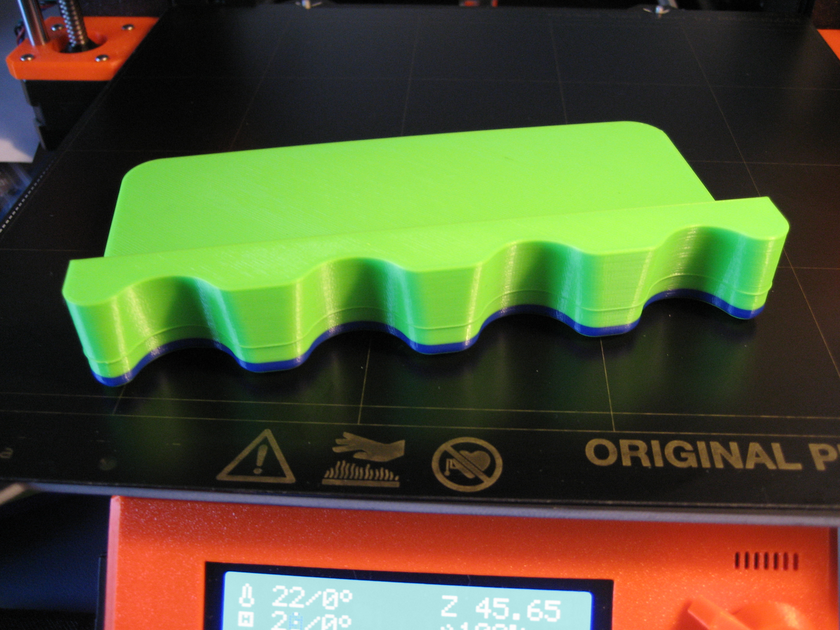
In the picture above you can see that there is a relatively large flat ledge with a raised section above it. This is on an MK3 with more or less out of the box default settings ( some 1st layer extrusion changes that will not affect the print). it is 0.15mm layer height. Top layer # is 7 and the problem presents in those 7 layers and the very first layer of the raised section. Other than those layers the walls and print are fine.
In the this picture you may not be able to see it well but the bulge layers go all the way around the print. In other words it is not just on the raised section of the print.
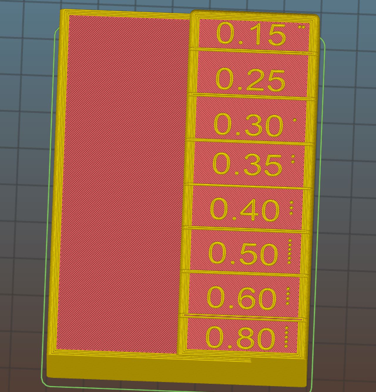
This diagram is just for reference when discussing location and direction of test prints:
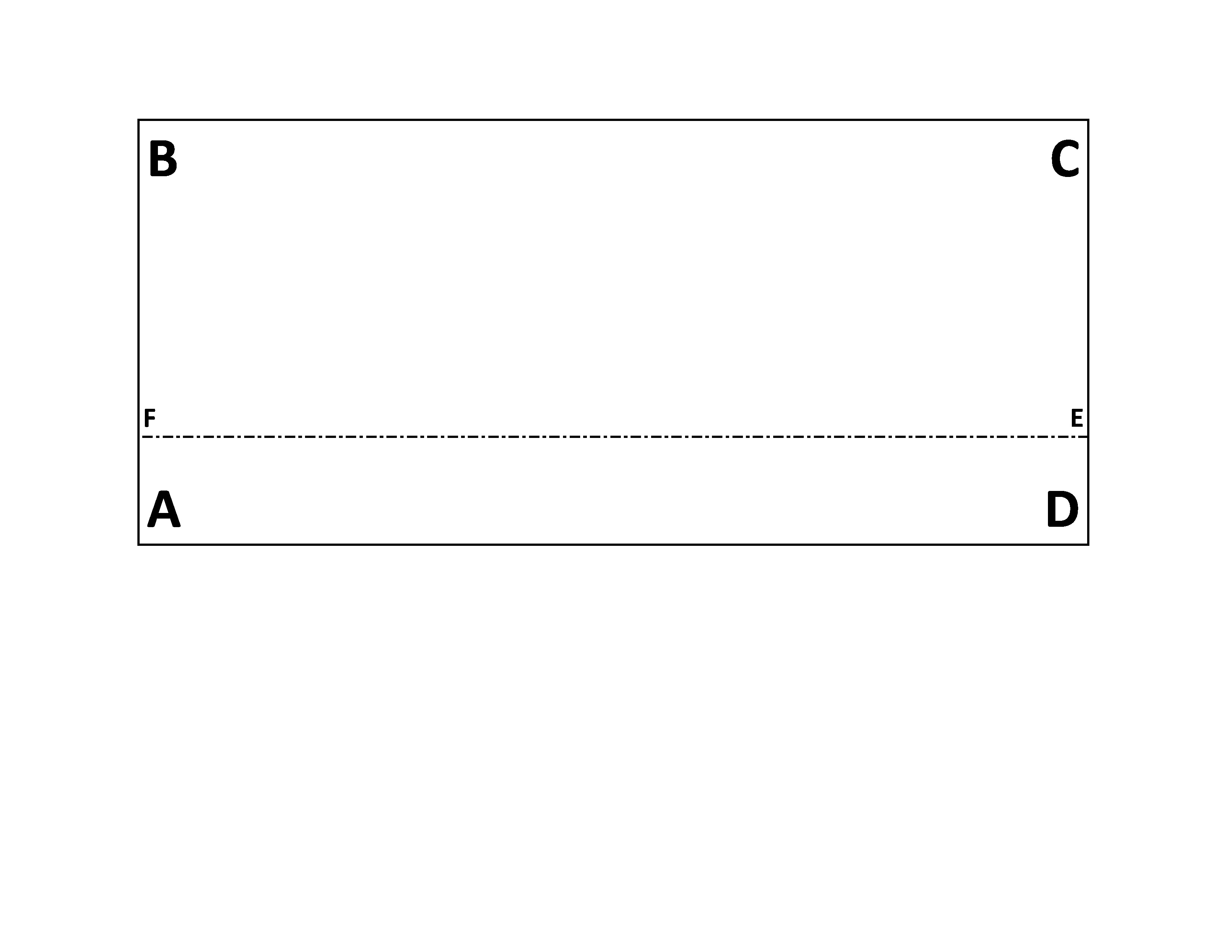
The dotted line is the boundary of the raised section.
So if we look at corner A for the last (7th or top layer) of the flat surface the perimeter is widest in that corner both in x and y directions. As that layer perimeter moves to either B or D it becomes less wide and then is wide again at C. The exact opposite is true for the 6th layer (layer beneath top layer of ledge). It is the widest layer at corners B and D and is narrower at A and C. Fifth layer is wide again at A and C though not as wide as the 7th layer (ie it becomes worse the more solid layers there are). etc etc So the 7 solid layers are slightly parallelogram in shape, shifted or skewed every other layer, on top of rectangular perimeters (below the solid layers).
I point this all out because I think it may be integral to the problem.
End result is something that looks like a total wide band but is actually layers that are wide in certain corners and not in others. The problem on the object in the picture is exacerbated by the concave curved sections and that those sections are 10 degrees off of vertical which results in two wider layers oozing past a narrower layer and joining (obviously temp can be used to mitigate some issues but does not solve the problem).
Re: Buldge when print reaches "solid" layers
PART 2 OF 3
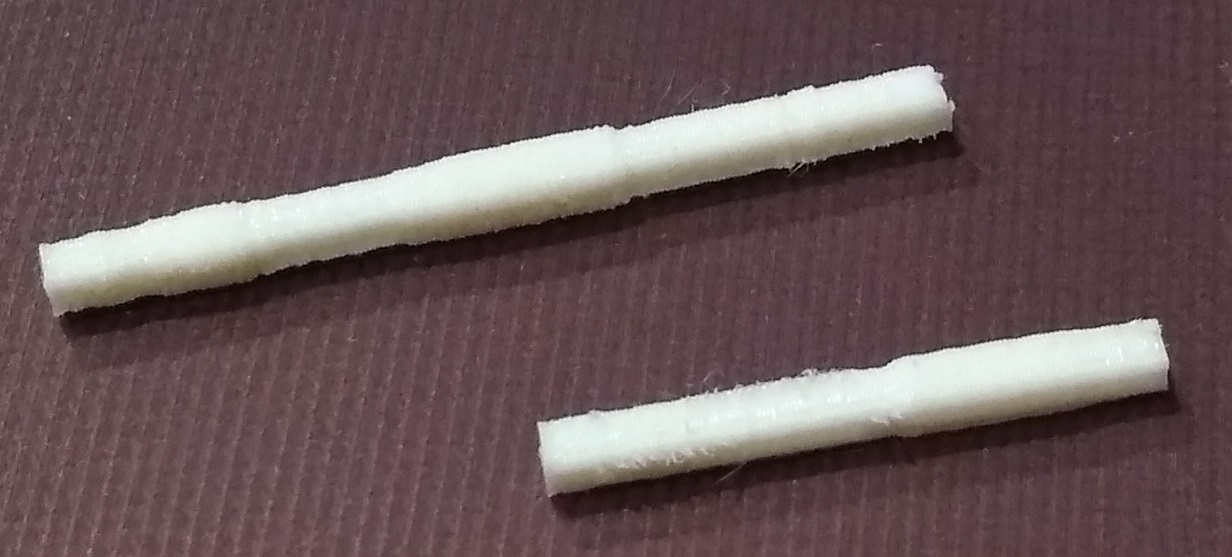
The problem is directly correlated with the rectilinear solid infill. Change the order of printing perimeter and infill or change the angle of the rectilinear infill and results will change. Print the same object with no solid top layers and the problem disappears (first pic below). Print with, say, 3 top layers instead of 7 and the problem lessens (2nd pic, 3 layers on right, 7 layers on left).

Exactly WHY it's correlated is a different issue. Is it the rectilinear motion or some other characteristic of the solid infill?
The way it presents is thus:
If a solid infill begins at E and continues its rectilinear motion in a general A to C direction (I know the shape doesn't allow for that exact motion but more or less) then the fill ends in corner B. If using perimeters first then the next layer's perimeter will begin in B (if using "nearest" setting but regardless) and it will always be too far into that part in that corner (B and D too far in, A and C too far out). If you change to "perimeters last" then that perimeter is still too far in but it is now the perimeter for the same layer not the next one.
SO WHAT PRECISELY IS THE ISSUE?
I see 3 primary possible issues but I would love to hear other's ideas.
1) Misalignment in X, Y, Z - i.e., the nozzle is in the wrong place in relation to the print (keep in mind everything has been in right place until these layers)
2) Extrusion - too much or too little filament extruded on perimeters of these layers at any given point on perimeter
3) Deformation of the print or more recent filament at some point after the perimeter is printed
I have tried a LOT of experimenting in an effort to determine possible solutions to this issue:

Re: Buldge when print reaches "solid" layers
PART 3 OF 3
Based on what I've done so far I believe the problem to be misalignment rather than extrusion or deformation. Again, would love to hear other ideas. In the interest of thoroughness, however, I will lay out possible causes of the 3 possible issues and discuss my rationale.
MISALIGNMENT
There is a whole slew of possible causes of misalignment:
-software (design or slicer)
-firmware (interpreting gcode or maybe in particular bed leveling and z axis adjustments)
-mechanical (backlash or other hysteresis)
-frame (twisting, shifting)
-material (solid layers physically impacting nozzle placement)
-print parameters (speed, jerk, accel, wipe before z change, etc all might impact the nozzle's motion differently for these layers
-resonance - related to parameters something causing over-adjustment in nozzle motion
Many parameters may be impacted by these and I've tried adjusting as many as possible to no great effect.
EXTRUSION
Issues related to extrusion:
-Software
-firmware
-nozzle pressure
I do not believe extrusion to be the problem. There are a couple tests I did which led me to this conclusion. First on test objects the "problem" corrects itself after the first layer following the ledge solid layers. The raised section is smaller in perimeter than the lower portion of the print. In terms of linear motion the perimeter is less on these layers.
When I printed with a full minute pause between solid layers the issue did not go away. I would expect, perhaps, nozzle pressure to alleviate a bit due to ooze.
The bigger convincer, however, was when I printed a test object with a 2 loop skirt that was higher than the corresponding flat layers. The issue presents in BOTH the skirt and the object. If it was a resonant nozzle pressure or something similar the issue should have resolved during the 2 loop skirt.


DEFORMATION
Possible causes of deformation could include:
-Cooling
-filament characteristics
-fill pattern (and associated thermodynamic characteristics)
-direction of fill (if pushing out or pulling in perimeters)
This is something I first thought might prove promising. OP solved part of his problem by using minus 30% overlap which says this may be a contributor. BUT it is not the primary issue in my mind because:
The same 2 loop skirt print above would not show ANY deformation in the skirt layers adjacent to the solid layers of the main print.
THINGS I'VE TRIED
Rather than go into even more detail and too many pictures I will just list what I've done and any noteworthy outcomes. These are things I've played around with:
-Print speed, acceleration and jerk settings
-Belt tension (x and y both around 280 on PRUSA status, tightened further, will tighten more when move to MK3S configuration). I don't think it is solely play as I don't see that having the parallelogram look of too far out at one corner and then too far in. Play should just lessen linear travel and that should be evidenced in all layers. Play in conjunction with some other factor maybe so. I printed hysteresis tests and did not see much play evidenced
-Extrusion width
-Linear Advance
-Temperature
-Overlap %
-Perimeters printed first vs last - this directly impacts the layers!! If a certain layer is too far out in Corner A if I switch to print perimeters last it will be too far in...and every other layer/corner combination will be flipped as well. THUS, the anomaly has a correlation of 1 with the PREVIOUS solid layer. This is also why if I print perimeters first the very first (AND ONLY FIRST) layer of the raised section will exhibit the issue - it is evident due to the last solid layer
-Different slicers (SLIC3R, CUra)
-Different filaments (lighter colored show up more and "oozier" ones show up more but that is not root cause
-Fill angle - this does impact results changing but not eliminating the problem
-Object orientation - a 1/8 turn does lessen the issue at least for some prints
-Cooling - fan speed, programming a pause, minimum time for layer prints (not an issue)
-Number of perimeters
-Number of Top layers - This DIRECTLY impacts the result, less layers = less problems. No layers = no problem
-Fill pattern and percent
-No wipe on z raise
-Probably other stuff I'm neglecting to remember
OTHER THINGS I WILL TRY AFTER UPGRADE TO MK3S
-More belt tensioning (Tim said it helped him)
-Measuring if frame is square, parallel and planar in aspect. THIS I believe could be an issue and would result in the layer pattern shown if somehow the back and forth rectilinear motion causes the frame and axes to get out of alignment. If the x-axis has a twist and the y-axis has a twist in the build plate then you would get the parallelogram shape. After the next fill pattern (direction is normal to the previous) then the "twists" would have to be in the other direction.
-Measure for this twist with a dial gauge
-code a gcode motion after each solid layer that is normal to the previous fill angle to see if repeated motion is causing this twist (if it exists). Repeated motion as a cause could be mechanical, firmware, frame or electrical in nature I suppose
-z-axis testing - if bed leveling adjustments are somehow getting off during solid fill
MITIGATIONS
In the absence to solutions regarding the underlying issue does anyone have ideas for mitigating the problem? Here's what I've found helps:
-Number of top layers - less layers=less problems
-Object orientation - does seem to help to align perimeters with infill angle, but this is not ideal
-Solid infill pattern - this might help but in SLIC3R at least (other than topmost layer) there is no way to change from rectilinear
-Filament characteristics, changing temp, perimeters etc for impacted layers - a pain, but doable
-Top layer pattern - one thing that does hold promise is to put in a pattern that extends below the top layers.

This is feasible for me although would take work to find the right pattern that slicer doesn't just put a whole new solid layer under. Anything that reduces the surface area of the flat "ledge" has a corresponding reduction in the problem it seems.
-Overlap % - helped nicolai
Any other ideas?
I would love to hear from PRUSA. For those of us using this as a tool for prototyping and considering it as a method for small run manufacturing it is something of a deal breaker. The part in the first print requires both reasonable cosmetic appeal AND functional utility. While it doesn't have to be perfectly smooth having a large layer bulge on the perimeter is not good. No doubt this is something I've done in my ineptitude but still doesn't change the fact that I need to fix the issue.
All in all, however, and in all seriousness, have LOVED this machine and am very impressed with the company. Just need to figure this out.
CHEERS!!
Re: Buldge when print reaches "solid" layers
At this point, I think the only testing that can help with hour specific issues would be to upload the identical gcode that's producing these results and let others try it on their printers. In particular, I'd very much be interested in printing that gcode with the extended skirt, along with the STL for comparison.
[...] Based on what I've done so far I believe the problem to be misalignment rather than extrusion or deformation.
Would it be a true statement to say that the layers that protrude are those with the greatest amount of solid infill?
Unfortunately, I won't be able to give it a go until next weekend at the earliest.
Re: Buldge when print reaches "solid" layers
The response by bubnikv say enough for me: Physics
His explanation that molecule chain alignments explain enough of the phenomena is satisfactory. The perimeters layer that are "wide" are due to mostly thermal side effects. And it makes sense: those bulging layers have more heat in them, and the plastic responds accordingly. It explains the large surface area effect well enough. An anneal may be useful.
The small surface area changes though, not necessarily a bulge and unrelated to adjacent flats, but rather the change in perimeter at certain layers around the hole in Bob's test piece; well, those still stump me. I can't figure why a given part size would affect printing to the point of steps in the perimeter size. If it were something simple like physics, both sides of the hole would be similar: but they aren't. So it's something more mundane. Non-linearity in the extruder speeds, or filament volume not fitting the mapped profile, or least likely something in Slic3r's math. In my best test case, it appears not to be a wall thickness change, but an offset in the build up. The thickness is the same above and below the "defect" but is offset a fraction of a mm. Time to bury myself in the gcode. Anyone know of a good visualizer?
And my final WTF is that my bridging is no where as good as any of the other samples shown here; and it has me really baffled. Maybe I'll just blame the Mystic Brown filament.
Re: Buldge when print reaches "solid" layers
Rick:
Yes, If you would like to post the STL or PM it to me, I will print it tomorrow and post the results to show if it does it or not to help. I do not know if this item is something you may not want out in the wild or not, but I will give it a try if you want...
At this point, I think the only testing that can help with hour specific issues would be to upload the identical gcode that's producing these results and let others try it on their printers. In particular, I'd very much be interested in printing that gcode with the extended skirt, along with the STL for comparison.
[...] Based on what I've done so far I believe the problem to be misalignment rather than extrusion or deformation.
Would it be a true statement to say that the layers that protrude are those with the greatest amount of solid infill?
Unfortunately, I won't be able to give it a go until next weekend at the earliest.
Strange women, laying in ponds, distributing swords, is hardly a basis for a system of governance!
Re: Buldge when print reaches "solid" layers
At this point, I think the only testing that can help with hour specific issues would be to upload the identical gcode that's producing these results and let others try it on their printers. In particular, I'd very much be interested in printing that gcode with the extended skirt, along with the STL for comparison.
[...] Based on what I've done so far I believe the problem to be misalignment rather than extrusion or deformation.
Would it be a true statement to say that the layers that protrude are those with the greatest amount of solid infill?
Unfortunately, I won't be able to give it a go until next weekend at the earliest.
For my parts the layers that extrude are only those that immediately follow a solid layer infill. So if I use 7 top layers and perimeters first, the protruding perimeters are only in the set of the final 6 layer perimeters and the 1st perimeter after the transition to the raised section.
I agree that the most interesting result is the one with the skirt. Primarily because I think it eliminates thermal characteristics AND overextrusion due to nozzle pressure, etc, as a primary cause.
I will try to come up with a part that doesn't take too terribly long to print that has the skirt issue present itself and post that and the STL.
Re: Buldge when print reaches "solid" layers
Rick:
Yes, If you would like to post the STL or PM it to me, I will print it tomorrow and post the results to show if it does it or not to help. I do not know if this item is something you may not want out in the wild or not, but I will give it a try if you want...
At this point, I think the only testing that can help with hour specific issues would be to upload the identical gcode that's producing these results and let others try it on their printers. In particular, I'd very much be interested in printing that gcode with the extended skirt, along with the STL for comparison.
[...] Based on what I've done so far I believe the problem to be misalignment rather than extrusion or deformation.
Would it be a true statement to say that the layers that protrude are those with the greatest amount of solid infill?
Unfortunately, I won't be able to give it a go until next weekend at the earliest.
Thanks JB! I will try and come up with an object that doesn't take too long to print that still has the problem.
Re: Buldge when print reaches "solid" layers
The response by bubnikv say enough for me: Physics
His explanation that molecule chain alignments explain enough of the phenomena is satisfactory. The perimeters layer that are "wide" are due to mostly thermal side effects. And it makes sense: those bulging layers have more heat in them, and the plastic responds accordingly. It explains the large surface area effect well enough. An anneal may be useful.
The small surface area changes though, not necessarily a bulge and unrelated to adjacent flats, but rather the change in perimeter at certain layers around the hole in Bob's test piece; well, those still stump me. I can't figure why a given part size would affect printing to the point of steps in the perimeter size. If it were something simple like physics, both sides of the hole would be similar: but they aren't. So it's something more mundane. Non-linearity in the extruder speeds, or filament volume not fitting the mapped profile, or least likely something in Slic3r's math. In my best test case, it appears not to be a wall thickness change, but an offset in the build up. The thickness is the same above and below the "defect" but is offset a fraction of a mm. Time to bury myself in the gcode. Anyone know of a good visualizer?
And my final WTF is that my bridging is no where as good as any of the other samples shown here; and it has me really baffled. Maybe I'll just blame the Mystic Brown filament.
That link was a good find Tim. Very informative read.
From my recent lengthy sleep inducing set of 3 posts. The following 2 pics show the same bulge occurring in the skirt as in the object, so thermal expansion/contraction can't really seem to explain the problem that I have seen. Certainly is logical and may explain it in other cases or may contribute to all cases.
Re: Buldge when print reaches "solid" layers
Yeah - the skirt poses a problem. Somewhere, and sorry, but I can't find where it was to point folks to it, I read that in the printer firmware was a function to normalize the filament flow; and I get fuzzy here: the normalization was to help with nozzle temperature stability; so the firmware would alter the extrusion amounts so that the temperature (or power consumption) was somehow maintained semi-constant and would not require instantaneous heat pulses for printing parts that have large then small extrusions. The takeaway I had at the time was this thermal response tweak could cause thick and thin spots at unpredictable points in a print. Large areas of extrusion followed by small areas would suffer. At the time I was trying to understand changes in the posts on the printer test (should be a tall square, but changed size whenever another area of the part went away.
This effect sort of explains the fat layer in the skirt. The solid infill is chewing away the watts, and the firmware doesn't want to reduce power rapidly thus more heat / filament gets dumped into the skirt than is actually needed.
Here's the posts I referred to:
Re: Buldge when print reaches "solid" layers
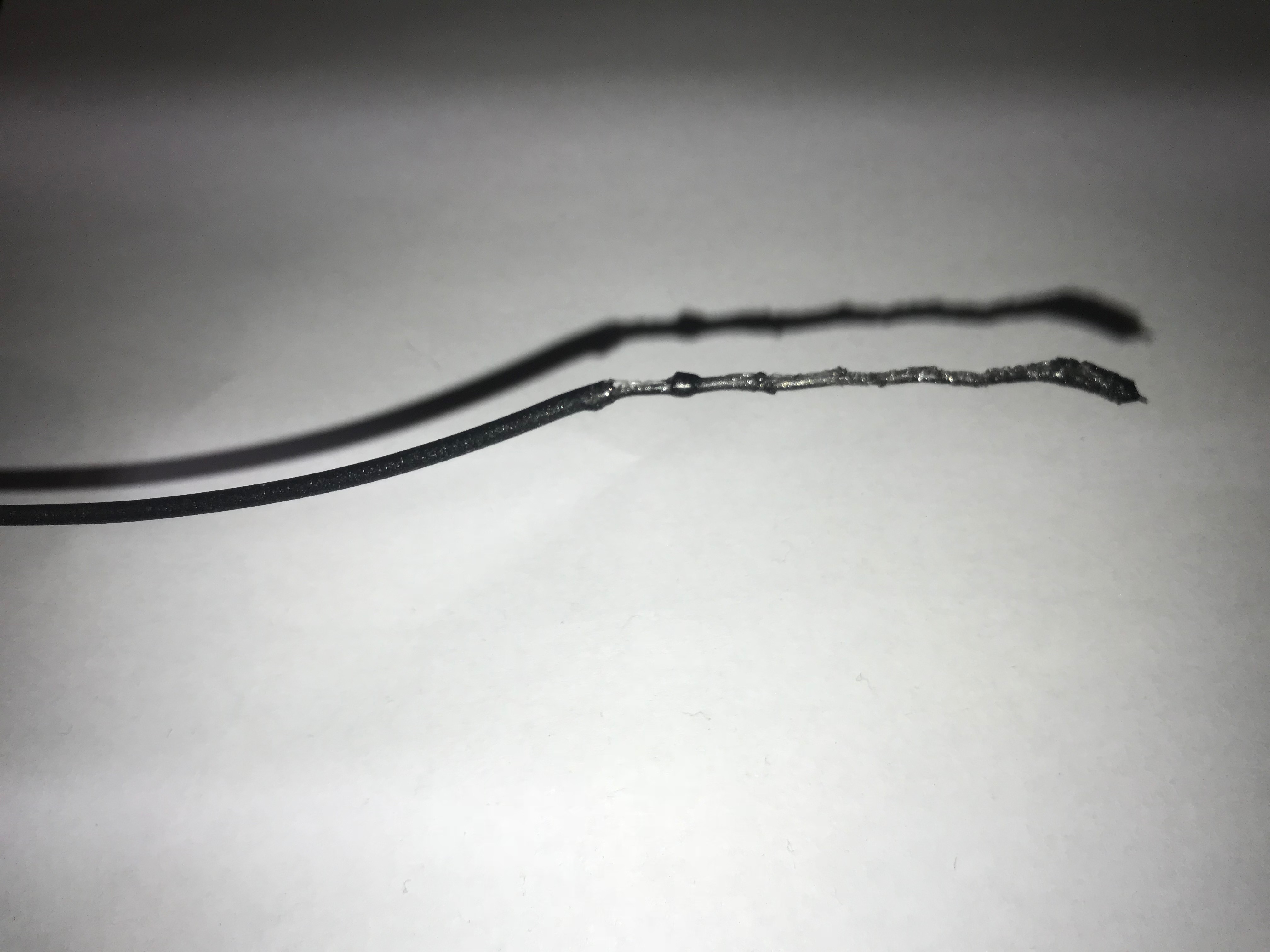
And a poor man's cross section of Bob's test print: this is the 1.5mm version, and after a very poor anneal (like 20c too hot) ...
You can almost see the fact the sections are offset - the wall is 1.5 mm with small offsets along the way. I'll spend some time tomorrow trying to improve the grind to show the effect more clearly. But it's obvious under a magnifying glass.
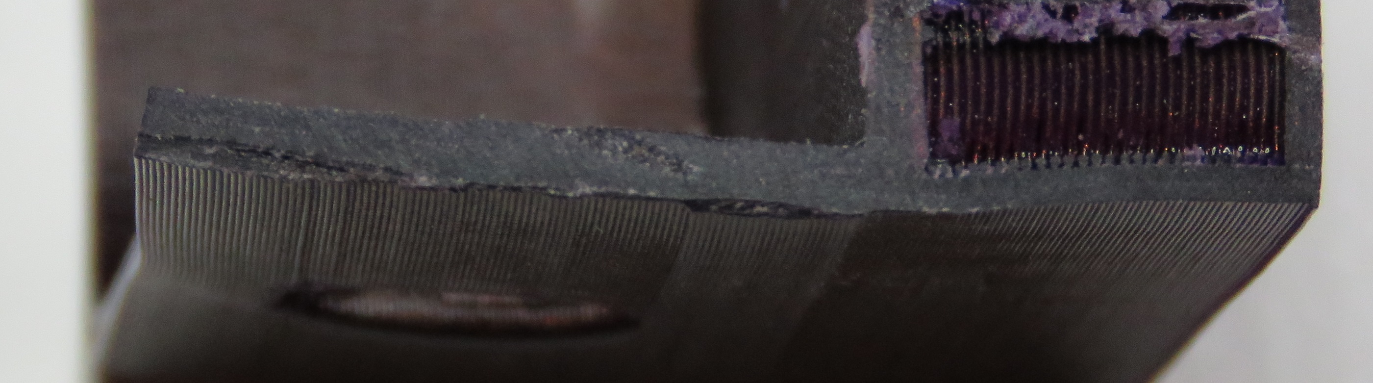
ps: this appears to be a different issue than the square posts shown above - where the extrusion is wider in both X and Y.
Re: Buldge when print reaches "solid" layers
Yeah - the skirt poses a problem. Somewhere, and sorry, but I can't find where it was to point folks to it, I read that in the printer firmware was a function to normalize the filament flow; and I get fuzzy here: the normalization was to help with nozzle temperature stability; so the firmware would alter the extrusion amounts so that the temperature (or power consumption) was somehow maintained semi-constant and would not require instantaneous heat pulses for printing parts that have large then small extrusions. The takeaway I had at the time was this thermal response tweak could cause thick and thin spots at unpredictable points in a print. Large areas of extrusion followed by small areas would suffer. At the time I was trying to understand changes in the posts on the printer test (should be a tall square, but changed size whenever another area of the part went away.
This effect sort of explains the fat layer in the skirt. The solid infill is chewing away the watts, and the firmware doesn't want to reduce power rapidly thus more heat / filament gets dumped into the skirt than is actually needed.
Here's the posts I referred to:
IMG.jpg
Capture.JPG
In all my musing on the subject I have thought about power issues and if they might be impacting my print. Very similar to what you are talking about here. Almost an electrical hysteresis if you will that the solid layers with their back and forth x and y axis changes might somehow cause firmware or the motors themselves to get off a tiny bit. That would help explain the skirt although it seems that it would then be gone by the time it got to the perimeter.
The whole parallelogram look of too wide then too narrow might fit that too, the firmware going to far in one direction, then over-adjusting too far in the other, etc. until it gets back on track.
Definitely something going on.
I have designed a part to share (Bobstro and JB) that takes less time to print and will hopefully show my problem, but I am in the middle of the upgrade to MK3S (S is for "Super" I hope) so I'll post it after I get that completed.
Re: Buldge when print reaches "solid" layers
Hmm. Very interesting, especially the cross-section. Unfortunately, I'm on the road until next Sunday, but I'd be very curious to see if disabling Linear Advance has any impact?
Re: Buldge when print reaches "solid" layers
New data point. Printed two of Bob's parts, one rotated 90. The rotated part shows no signs of steps at the layers of infill while the part not rotated shows the odd steps ... printed at the same time. Makes zero sense unless the issue really is as simple as print accuracy.
I tightened up my Y-belt and tried again. I want it to be better, so I see a difference, but I doubt it's measurable.
I have one more out of the box test to do ...
Re: Buldge when print reaches "solid" layers
Printing a benchy i had the same problem.
Where the deck of the benchy was, a thick line.
" External perimeters first" helps a little.
Extrusion multiplier, try smaller setting.
I was working with pla black, and saw a part of the benchy was shiny and the other part not shiny.
Then i adjusted the temp, higher.
10 or 20 higher, 240 for pla(usually 220).(the whole print was shiny).
Then the thick line was gone.
And i am confuse, why why ???
But it worked.
Re: Buldge when print reaches "solid" layers
That would seem to point back to a mechanical issue, wouldn't it? I'd have thought having the flat surface aligned on the X axis (left-to-right) would yield more consistent results than along the Y axis (front-to-back) due to bed weight. That does explain the ridge showing in the skirt as well. The variance between what each of us sees can be explained by minor differences in builds and belts.
New data point. Printed two of Bob's parts, one rotated 90. The rotated part shows no signs of steps at the layers of infill while the part not rotated shows the odd steps ... printed at the same time. Makes zero sense unless the issue really is as simple as print accuracy.
When I get home I'll try creating a square shape with the thin walls on 2 perpendicular sides to see what the impact is. I suppose having 2 connected walls, one each on X & Y, and 2 separated X & Y walls might be useful. I'll definitely use a taller skirt when generating gcode. I made my part thick enough at the bottom to show infill impact, but I'm thinking I can thin it down by half to speed up printing. I want to keep test prints below an hour.
I do want to repeat testing with Linear Advance disabled as well.
It would be awesome to see comparisons done with the same filament and settings, but with different motors and tuning parameters. Unfortunately, I'm not in a position to do that. I'd really like to see such a comparison done using the new Bondtech extruder!
I tightened up my Y-belt and tried again. I want it to be better, so I see a difference, but I doubt it's measurable.
That's the danger of chasing improvements using shiny filaments with worst-case lighting. It can look really bad even if you can't feel the difference.
We're at tolerances that would have been just fine working with wood or metal a few years ago. You'd sand and finish and off you go. We're chasing perfection with a simpler process. I've noticed this with people trying to produce display models. One group has a background in producing miniatures and sculptures, 3D prints a bust, spends a few hours sanding, priming and painting and gets great results that they show off. Another group expects display-ready output from the 3D printer with no additional work, gets the identical 3D printed result and is disappointed.
There's nothing wrong with getting the best possible results through tuning and calibration, but after the 602 fiasco, I'm willing to live with shiny filament looking less-than-ideal in certain lighting. I want to get the best results possible, but I don't think this is a fault of the Mk3 in particular, just the process and our collective experience. At some point, I'm going to say it just needs some finishing and call it done. For me, that's when I have a hard time feeling any difference dragging my fingernail across a surface. For sanity's sake, I'm thinking that any defect that doesn't show when printed using a matte finish is probably not worth worrying about.
Re: Buldge when print reaches "solid" layers
Sorry Tim, I missed some of your points during my travels this week...
Yes, definitely some differences between printers. Add in some variation in settings and filament and we're likely to be seeing very different results. I wonder how much nozzle wear comes into play as well. I've got a worn-out 0.40mm I'll try with.
[...] The slice is fine in all cases. I've done a manual look-n-see and on the same linear portions the extrusion gcodes match. Yet the actual plastic is different. It's machine variation. By the way, my printer isn't really exhibiting the issue nearly as much as others are reporting..
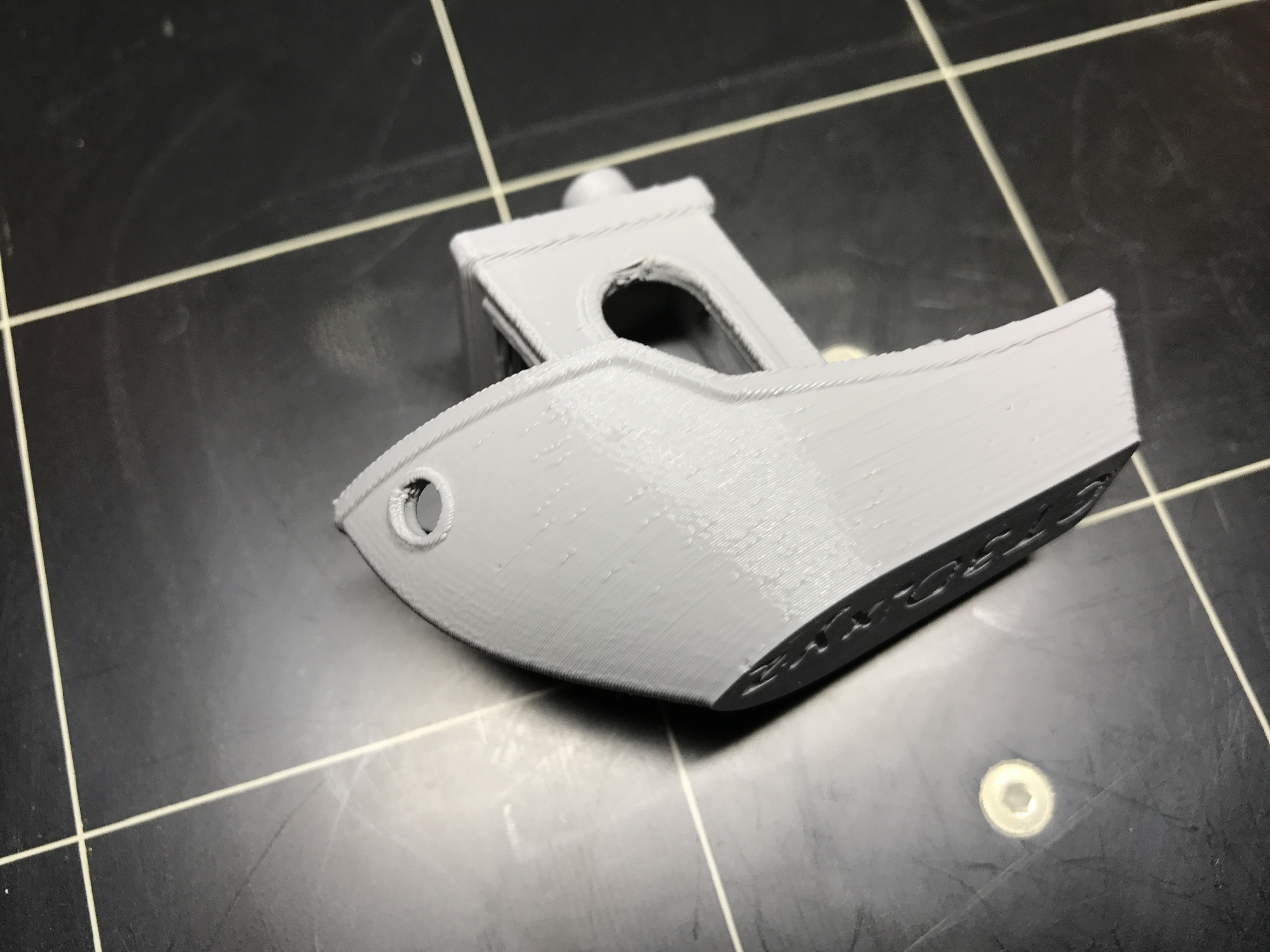
My most recent test I've changed the seam parameters (to random) and it has virtually removed any traces of the variation. Only one place where I can see any variation - at the junction of the top of the hole. And I have to be really picky to point it out.
I did try setting alignment to rear and didn't see much of a difference.
What has me baffled at this point is why the top of the hole is simply not bridging well. Seems even with bridge detection and ultra slow print speeds, the printer is doing some really weird crap. Detection is giving similar results to printing the area at full speed... and at this point I think full speed looks better ... lol.
I am worried that I'll go through all this to get perfectly smooth walls, only to have another issue crop up as a result. I'm sure there's a term for benchmark myopia. I want a nicer overall finish, not a perfect test print! 🙂