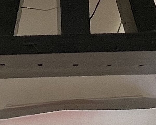
Bad print settings or poor design?
Hi all,
a few weeks ago I started a thread on problems with CPE and showed a part that had "inverse" warping, as in lifting in the middle rather around the edges. (See picture and .3mf).
While I was still procrastinating about what to change I was looking at the part again and it looks like the bend got worse over time. Now that is something I don't want to happen. Hence my question: was it poor printing or poor design or a combination of both?
I had the first prototype printed in PLA and the whole thing stayed nice and straight. Any suggestions how I could repeat that in CPE?
Apologies for re-starting this issue, but I dare say this is a slightly different angle compared to the original post.
Cheers
Hansjoerg
RE: Bad print settings or poor design?
I'm going with head-scratcher design. Why not take those little rectangles on the end of the large flat sheet and make them something you snap on later. That way you don't have that incredibly large (proportionally) bridge. The way it is I'd expect it to be a raft clean-up nightmare.
The long thin rod shapes will always be hard to print - brim and mouse ears are your best bet for that.
For the building on tripods, I'd recommend splitting it off of the sheet (use a piece of easy to buy acrylic or plexiglass for the sheet, or even plywood - way faster production - and then glue your little building thing on. I'd print that building thing upside down too.
If you can slot or emboss the long thin rods it will help with warping. Anything to break up the long runs.
Head-scratcher is why would anyone design this this way - when it would be so much easier to design it in parts and assemble it later. Gonna be a nightmare IMO to print clean and still get flat after it's all done (that's why I recommend plywood, plexiglass or acrylic sheet cut to size.) So cheap, so abundant, and nothing to fight with on the printer.
RE: Bad print settings or poor design?
Thanks Dan for your thoughts..
I expected that most of it would come down to rubbish design 🙂
A quick word on the overall design: the part seen here is the middle bit of a larger "sheet" (one more on each side). When assembled it will become a kinetic sculpture (the whole project started after a visit to the Len Lye Centre ( https://govettbrewster.com/len-lye/ ) and a few beers afterwards. It will be a motorized see-saw with printed grass blades on the plate swinging for- and backwards.
And indeed the acrylic sheet was the first option our little collective discussed but then 3d-printing pride and hybris kicked in. And similar to the hammer and nail approach, when you have a printer everything should be printed...
To help you with your head scratcher: I am definitely no engineer and part of the whole thing was to try and make the whole object out of printed parts (minus the arduino and the servo that drives it), so just file under artsy project (please include as many deep engineer sighs as you see fit) and indulge me 😉
The rod shaped things are the connectors for the plates and they came out perfect. The "little building thing" is en extension of the plate that holds the bearing for the axle.
The longer I think about this, the more obvious it becomes that it comes down to poor choice of material. I will get myself some nice black PLA and just do the grass blades in CPE.
Cheers
Hansjoerg
RE: Bad print settings or poor design?
@hawai
Looking at the other thread and photos, it appears you are printing infill much too fast and probably exceeding the material volumetric flow rate.
I'm not sure why that'd cause the part to warp upwards, but if the temperature differential is flipping - it almost makes sense, but not sure I fully understand why or how.
