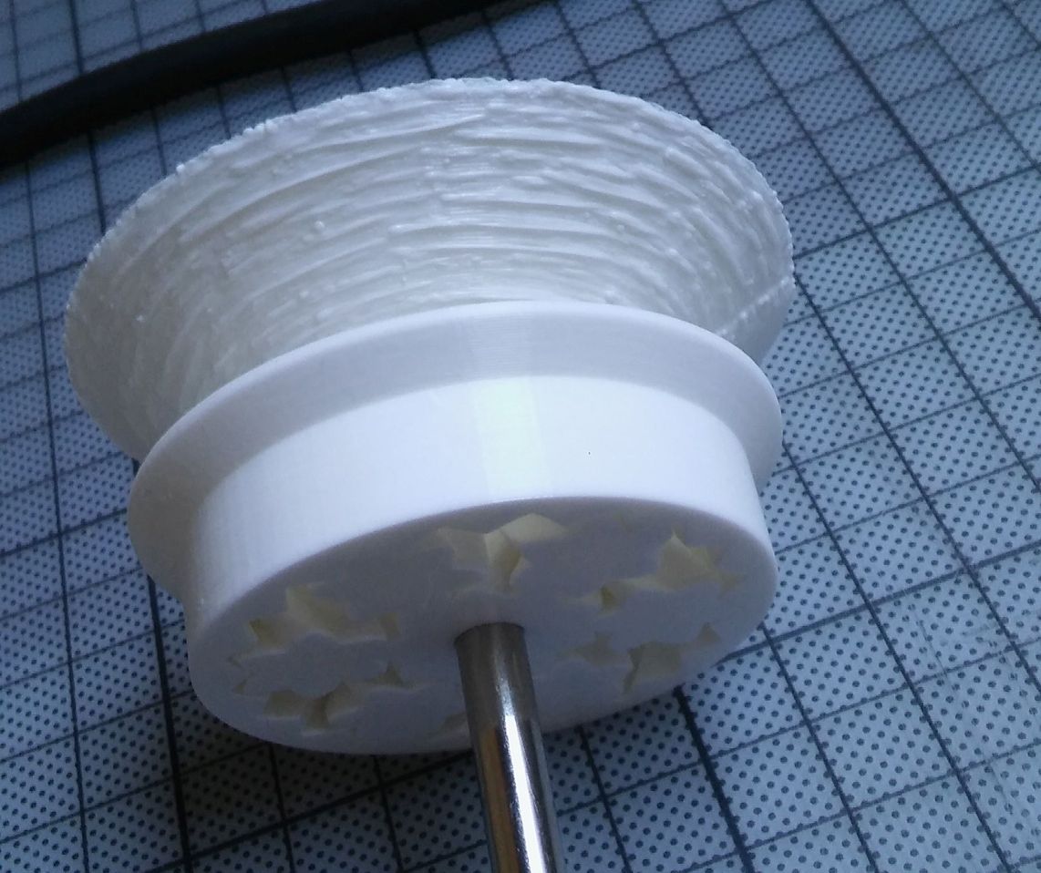
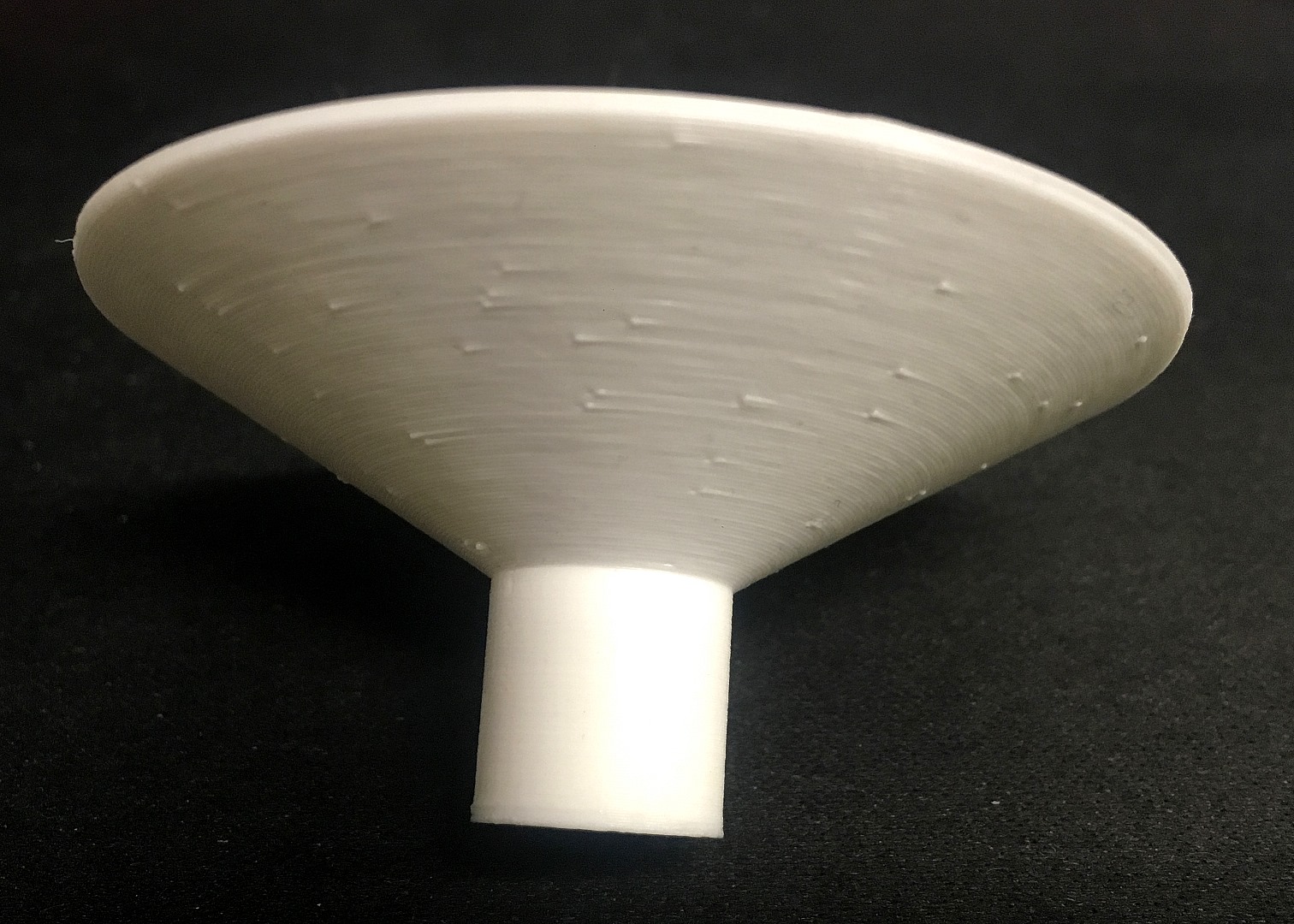
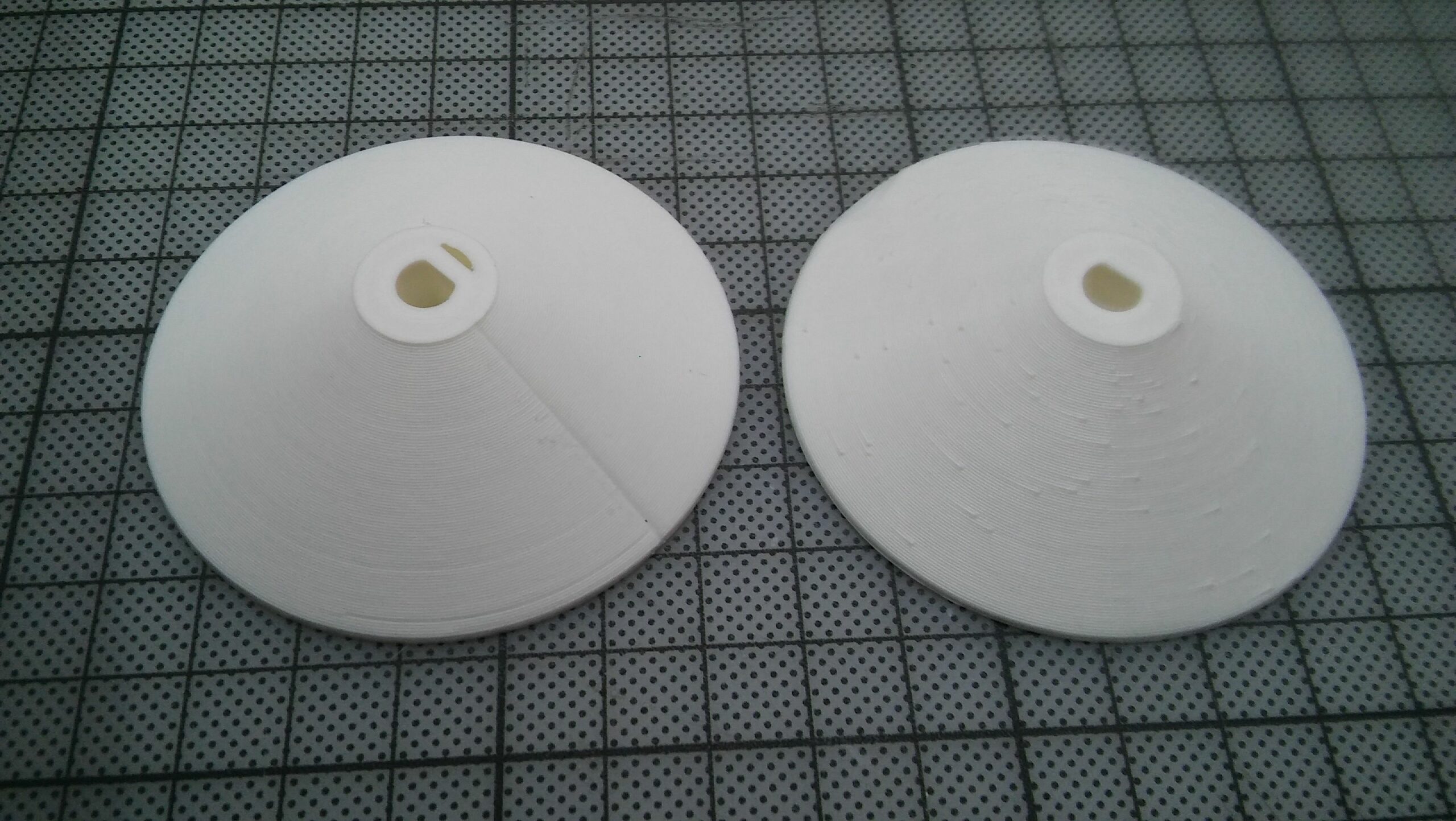
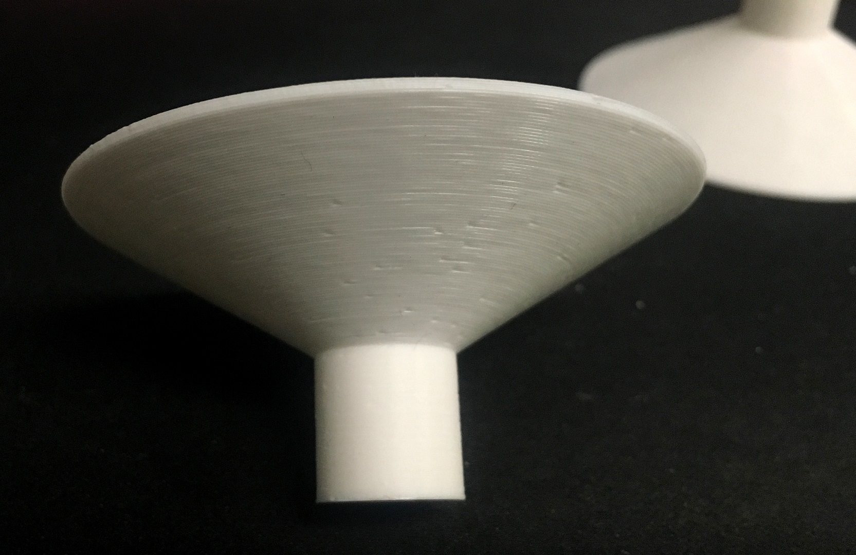
Messed-up overhangs - except for a quarter segment, which is somehow perfect
I was building a filament drybox, but one of the parts came out rather odd. To attach axle and bearings to the wall, I attached an upside-down cone to the model. At 60° overhang, it's right on the recommended limit, but I'd never had problems with that before (the little ridge on the bearing has the same angle, for example)
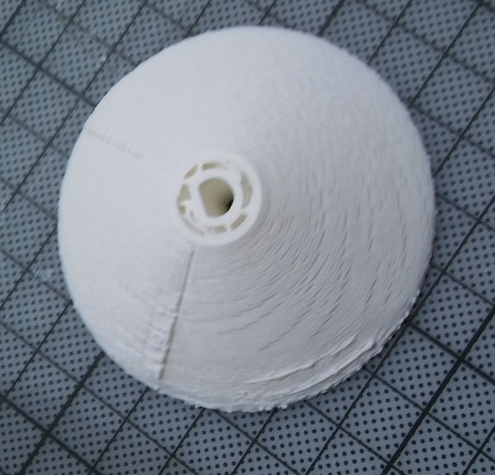
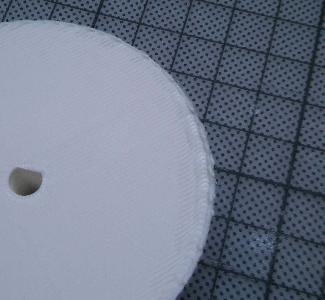
Mysteriously, one quarter of the cone came out perfectly (slight unevenness, but that's expected at this angle). The other tree-quarters are ridged and inconsistent unlike anything I've seen before. There's a fairly sharp edge between the regions, with little blobs attached. From other posts I thought it might be a cooling issue, except the good quarter is on the right side, not at all where the fan blows. Also, rather unexpectedly, the hole for the axle is much more uneven in the messed-up regions, even though it's nowhere near the edge.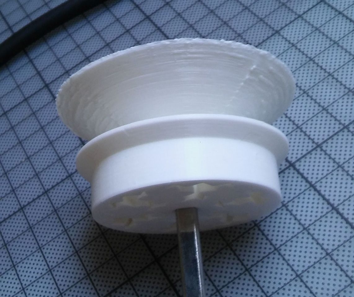
Apart from that, the only notable thing about my printer is that a string of filament usually runs out of the nozzle during warmup. I tried reducing print temperature, adding underextrusion and a custom g-code to retract the filament, but it didn't seem to do much.
Fortunately, I can still use the part. It just doesn't look as pretty.
Prusa i3 Mk3s, ~one year old; PrusaSlicer, PolyMaker PolyLite PLA (white)
@kevin-4
Looks like to much filament in to thin a wall to me, Post a zipped up .3mf project file and I'll take a look.
Regards
Swiss_Cheese
The Filament Whisperer
@swiss_cheese
Here, and also the gcode, if that helps.
https://forum.prusa3d.com/wp-content/uploads/2021/08/Anchor.zip
@kevin-4
Hi Kevin,
I took a look at your .3mf project file and made a couple of changes to the way it was being sliced, I used a height range modifier to remove the bottom layers in the 60Degree overhang area, I added in a perimeter in that area for strength, I believe the overhanging area was being viewed as all bottom layers by slicer and it was attempting to build the area up to try and meet the "Minimum shell thickness", there by putting to much heat and plastic in the area causing the problem you were seeing.
I didn't get a chance to test print, however I believe this will resolve the problem. Anchor_bottom_Swiss.Zip
Please let me know how it goes and post your results. I can provide more information if needed however I currently have time constraints, but I will check back.
Enjoy
Swiss_Cheese
The Filament Whisperer
@kevin-4
I got some time this evening to Print a test, based on that I made some substantial improvements to the file, here's Anchor_bottom_Swiss_V2.zip you can disregard the first posted file. The "Mysterious, one quarter of the cone came out perfectly" was actually where your retractions were taking place, and they can be adjusted for your filament and model specifically in the extruder settings or in filament overrides, I switched the seams to random so they wouldn't all be in one area.
Regards
Swiss_Cheese
The Filament Whisperer
I already made a print with the previous file, and it was a substantial improvement. Still some blobs around the retractions and the top is rather untidy, but much better. Need to check the new file though. (I cut off the bearing for faster print time)
this was the result I got from the second file, its a lot cleaner could probably stand to have the retractions adjusted but I don't know that it would really effect your dry box operation in any way.
the top and rim are also very clean.
Let me know how it goes
Swiss_Cheese
The Filament Whisperer
No picture this time because I screwed up the print. (I used it as a test for the drybox, but at some point the tube got itself stuck under the frame, preventing the filament from moving. I'll have to fix that.)
What printed was identical to yours, though.
So as far as I understand it, the critical parts are:
Having too much infill next to the perimiter can cause problems, so you need to check if the slicer places it somewhere unexpected. (bottom layers, vertical hull strength, etc.)
Outer perimiters first does wonders for accuracy (why isn't it on by default?)
Random seams prevents problematic material buildups
Look into the retraction settings to reduce the blobs in general
Right?
Another approach
I take a different approach with these sorts of prints. Starting with the results, with @Kevin's original settings on the left, moving to modified settings in the middle, and a few extra tweaks on the right:
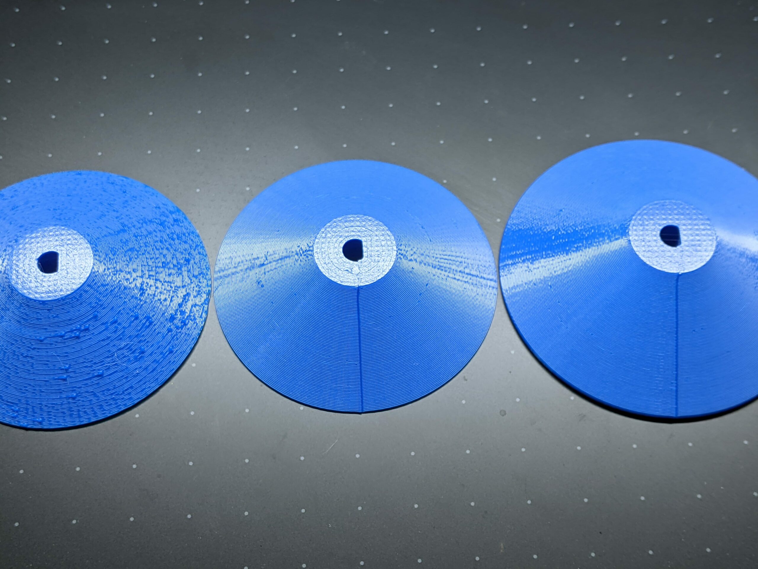
Notice the rough underside on the left. I stopped the 1st 2 prints to leave the top open (that's why they're a bit smaller) and set top layers to 0 on the right to show the inside:
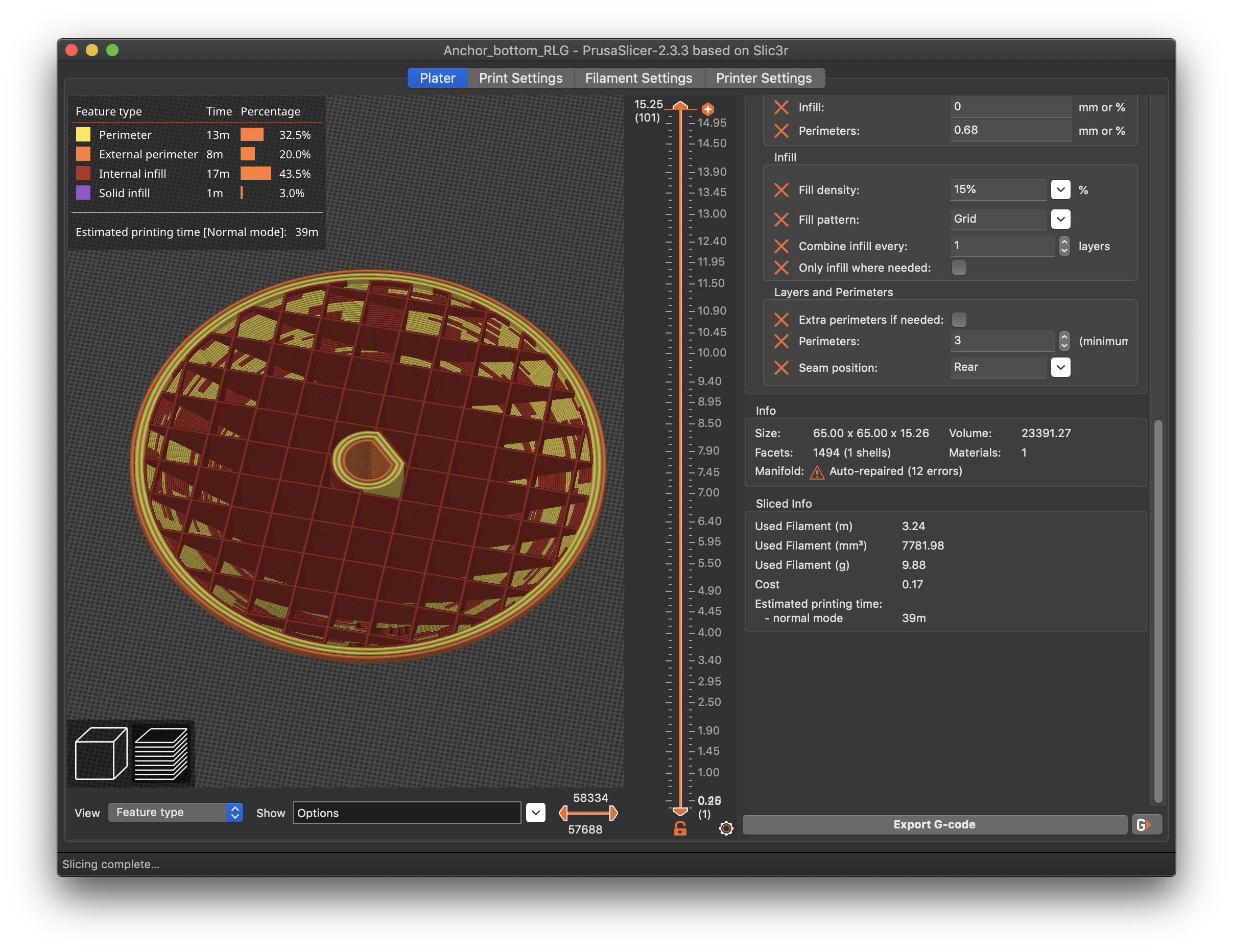
Here's what the slicer preview looks like with the original (left) settings:
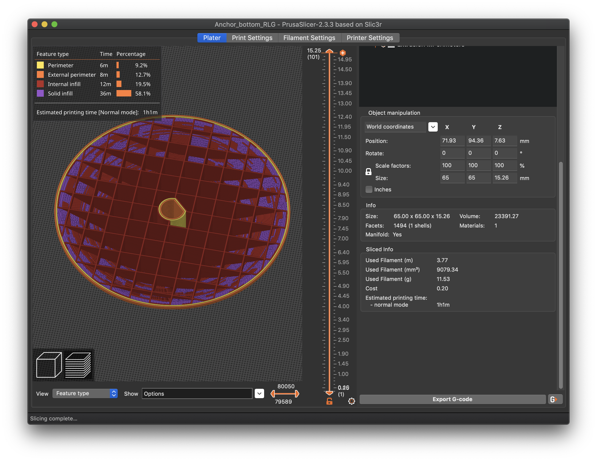
Notice all the fuzzy purple infill being created along the walls. You can see rough infill in the print if you enlarge the top view pic. That's because the overhang is too steep to print with that combination of layer height and extrusion width. PrusaSlicer is adding something to the inside for the infill to hold onto. This will add considerably to the uneven exterior appearance. The problem is apparent when you consider what the slicer has to contend with printing severe overhangs:
![]()
![]()
![]()
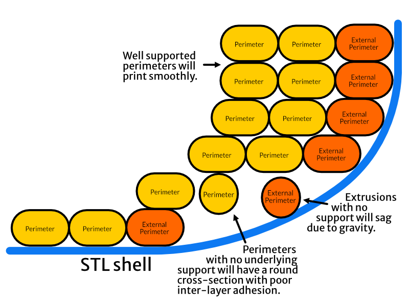
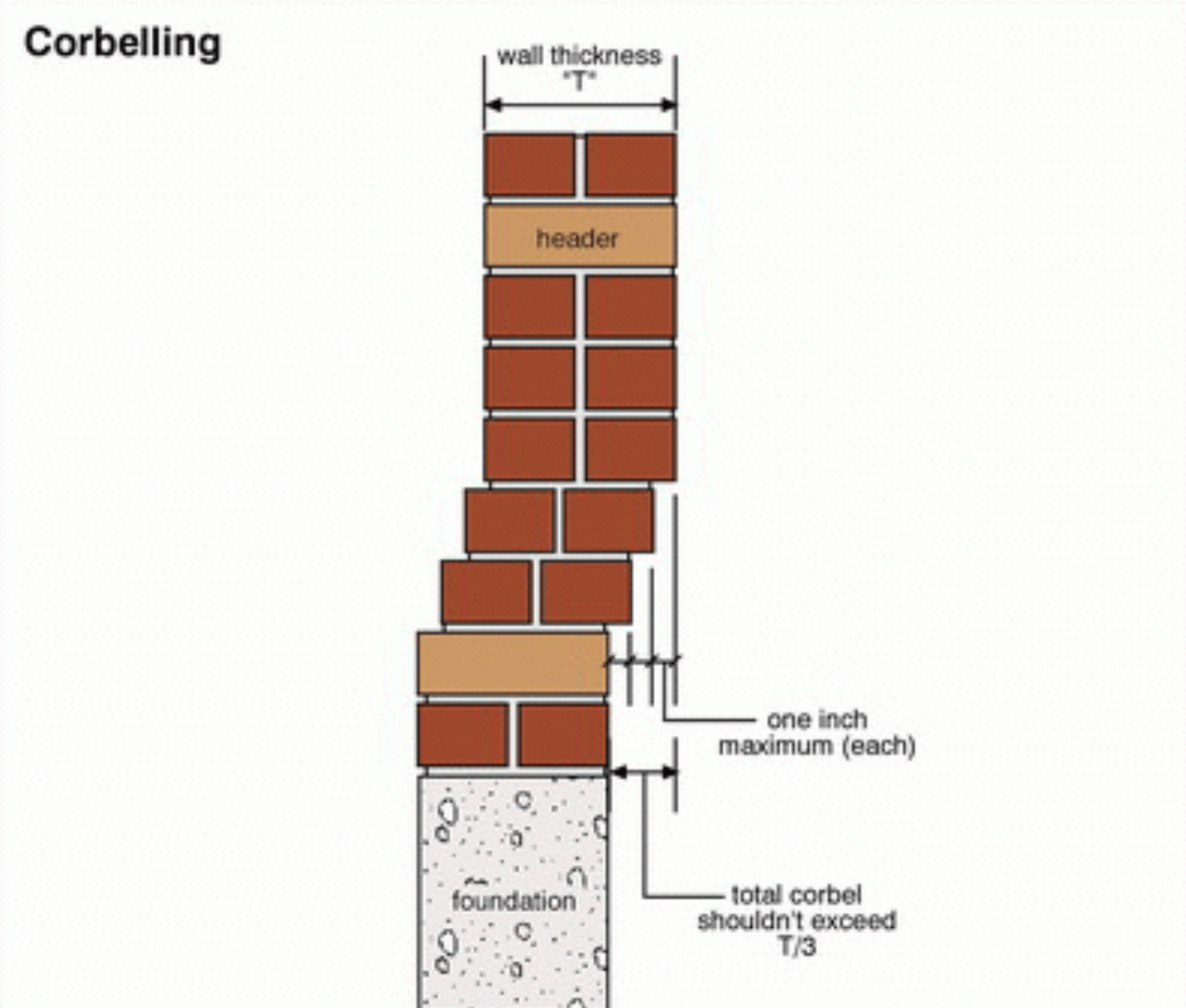
If the extrusions are too narrow and the overhang too severe, there's very little under each extrusion to adhere to, and you get sagging and deformation. In researching this, it struck me that bricklayers have to deal with the same issue, although their brick widths are fixed:
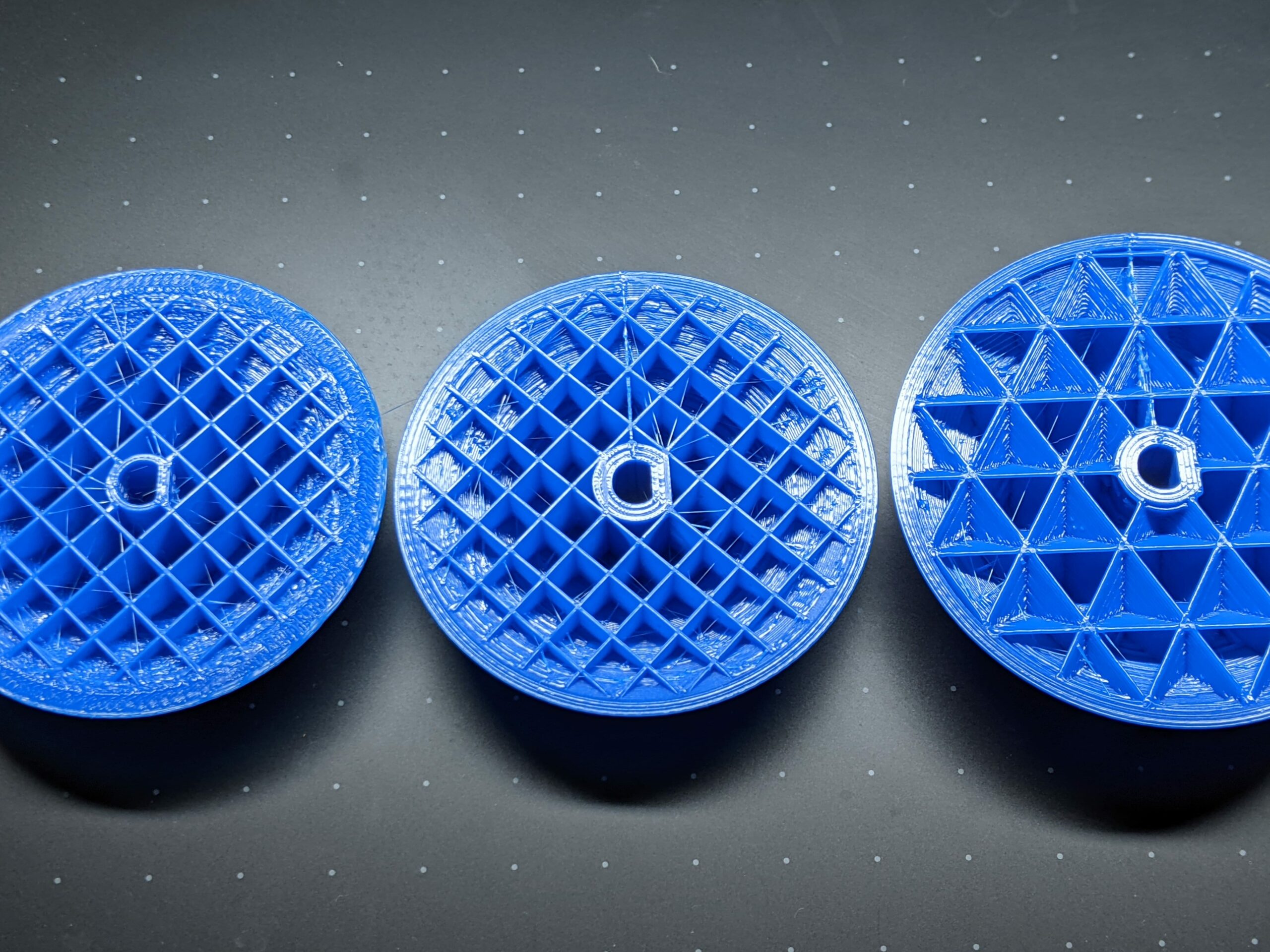
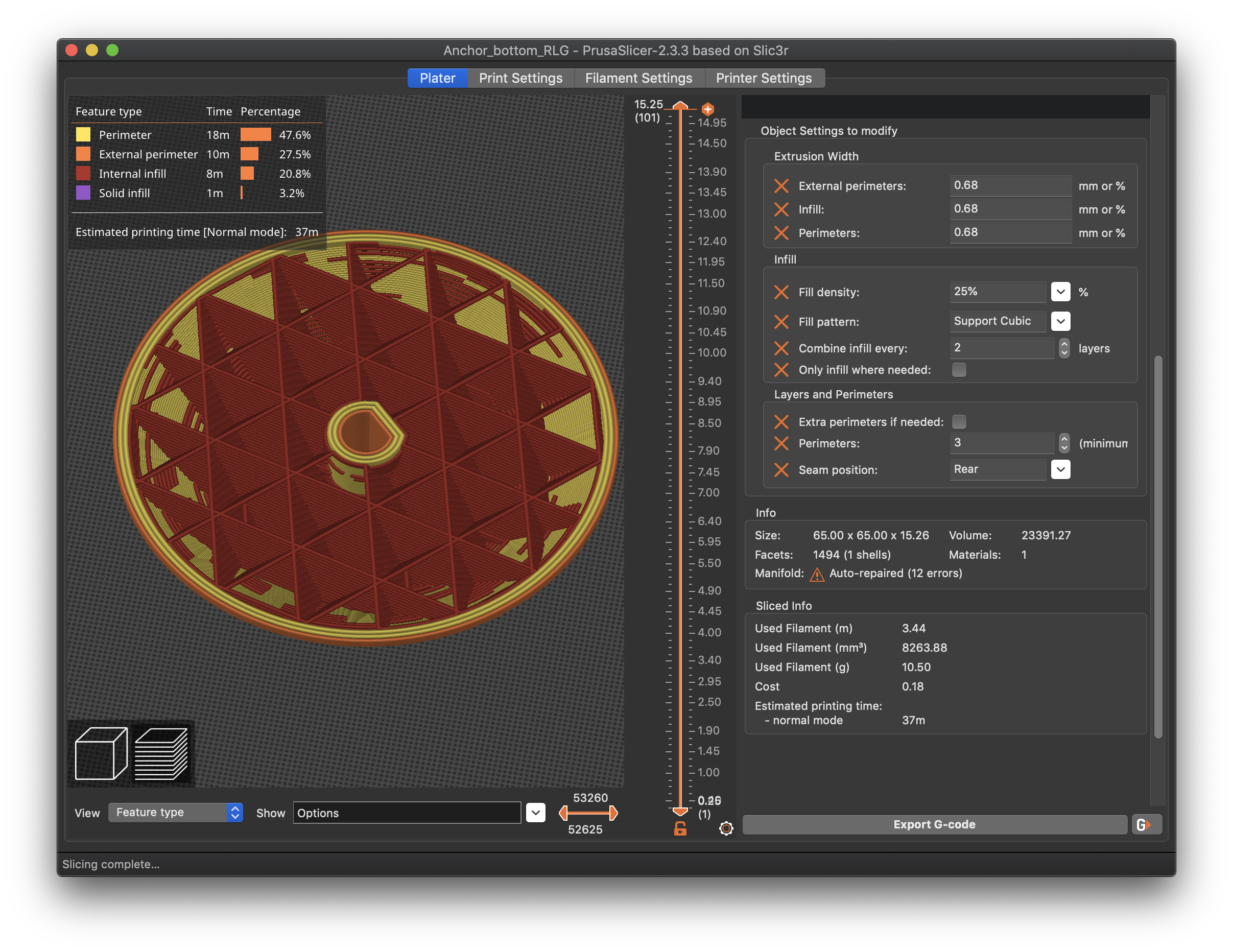
Here's the preview after making a few changes to the slicer settings:
Notice all the purple solid infill along the walls is gone, and the exterior walls are much smoother. This is all done with just a few default setting changes:
- Perimeters and external perimeters are set to 0.68mm width to provide more overlap between layers.
- Perimeters are increased to 3 to provide more even internal support.
- Disable Extra perimeters if needed since we're fixing that problem with explicit settings. (This often eliminates the extra solid infill purple fuzz.)
As an extra bonus, the walls are much more robust (possibly important for a load-bearing part) and print time has dropped from 1h1m to 39m. I also set z-seam alignment to Rear as I find it much easier to clean up a single line than bumps all over the print. I like to make a few other adjustments based on personal preference:
- Also increase infill width (0.68mm in this case). This yields more solid infill (although perimeters add part strength) and also enables the next setting to work well.
- Combine infill every X layers (2 in this case). Provided the combined layer heights don't exceed 80% of nozzle size, this works well and speeds up prints with lots of infill. (2 X 0.15mm = 0.3mm, so is fine for a 0.4mm nozzle).
- Change infill pattern to Support Cubic. This reduces the total amount of infill generated (though it's not a big difference at this scale).
- I increased infill density to 25%. With Support Cubic, this the top-most density that will be printed.
- Again, I prefer Rear z-seam positioning.
Print time estimate has dropped another 2 minutes and I prefer the overall result. These prints were made using a SPEED profile (sadly, not on my Prusa).
As far as using Outer perimeters first, that can add to the problem of printing overhangs as there's even less for the outer-most, first-printed extrusion to adhere to. I'd suggest addressing the underlying problem rather than trying to work around it this way.
I'd also suggest calibrating your extrusion multiplier as any slight over extrusion is going to enhance your z-seam defect and contribute to poor finish overall. Retraction, wiping, coasting, z-lift, and a lot of other settings are all workarounds to deal with stringing. Over-extrusion contributes to over extrusion, this eliminating the root cause.
![]()
and miscellaneous other tech projects
He is intelligent, but not experienced. His pattern indicates two dimensional thinking. -- Spock in Star Trek: The Wrath of Khan Unfortunately,…
Final settings...
Hmm. Final settings pic didn't show up:
and miscellaneous other tech projects
He is intelligent, but not experienced. His pattern indicates two dimensional thinking. -- Spock in Star Trek: The Wrath of Khan Unfortunately,…
@bobstro
So, wider perimiters and a better extrusion multiplier.
With some different parts I've had some printing issues and thought overextrusion might be a problem, so I just played around with some multipliers without improving it. Somehow, just measuring the wall thickness for the correct one completely went over my head...
(even though I had properly done measurements for the perfect first layer)
Oh, and I only learned about combined infill layers yesterday or so, I definetly need to try that one.
No picture this time because I screwed up the print. (I used it as a test for the drybox, but at some point the tube got itself stuck under the frame, preventing the filament from moving. I'll have to fix that.)
What printed was identical to yours, though.So as far as I understand it, the critical parts are:
Having too much infill next to the perimiter can cause problems, so you need to check if the slicer places it somewhere unexpected. (bottom layers, vertical hull strength, etc.)
Outer perimiters first does wonders for accuracy (why isn't it on by default?)
Random seams prevents problematic material buildups
Look into the retraction settings to reduce the blobs in generalRight?
Right.
However, perimeters first isn't always the best option. In this case it was, I used it to solidify the outer shell before the material behind it could have a chance in its molten built up state to push it outwards and cause material build up issues, you might have also noticed that I increased the width of the external perimeter for the overhanging section this had the effect of causing the external perimeters to overlap a little better making it print cleaner. remember that everything we do with our printers is minuet, the smallest adjustments can make big differences.
I still would like to see your results when you finish and are happy with it.
good luck and If you have any issues feel free to ask.
Swiss_Cheese
The Filament Whisperer
Visual method is fine
[...] So, wider perimiters and a better extrusion multiplier.
To be clear:
- The wider perimeters and extra perimeter(s) will often reduce or eliminate that fuzzy solid infill on the inside of sloping walls that shows up in purple in preview mode.
- Tightening up the extrusion multiplier will help reduce slight over or under extrusion that can exacerbate a number of problems, including a seam appearance.
With some different parts I've had some printing issues and thought overextrusion might be a problem, so I just played around with some multipliers without improving it. Somehow, just measuring the wall thickness for the correct one completely went over my head...
It doesn't have to be super precise. Just use the Visual Method from the Prusa knowledgebase article. Print a small cube and inspect it. If you see squishy corners or a lumpy top surface, reduce you extrusion multiplier 2% or so and try again. If you see gaps between top lines, add 1-2% and try again. Save a profile with the correction for each type of filament you use often, and repeat the process for new filament types. It's a quick process once you get the hang of it.
(even though I had properly done measurements for the perfect first layer)
Those are important, but different. With your calculated extrusion multiplier applied, your 1st layer should still be smooth and without gaps.
Oh, and I only learned about combined infill layers yesterday or so, I definetly need to try that one.
Watch out for the combined height, but it can definitely be a timesaver.
and miscellaneous other tech projects
He is intelligent, but not experienced. His pattern indicates two dimensional thinking. -- Spock in Star Trek: The Wrath of Khan Unfortunately,…
One more thought on extrusion..
If you start to get weird over extrusion problems using settings and filament that worked well before, don't overlook the possibility of your filament having absorbed too much moisture. This is really an issue in areas getting excessive humidity. (We've had "dangerous indoor humidity" alerts locally this year.)
Try another spool or dry your current spool before making wholesale slicer or printer setting adjustments. After drying, it may well recover.
and miscellaneous other tech projects
He is intelligent, but not experienced. His pattern indicates two dimensional thinking. -- Spock in Star Trek: The Wrath of Khan Unfortunately,…
Done!
Took a bit (working on the drybox), but here's the results.
bobstros settings on the left, Swiss_Cheeses settings on the right. Calibrated the extrusion multiplier, too (by a whopping 8%).
Overall, wider perimiters seem to be best. Even with the better multiplier, there's quite a bit of blobbing going on, but they're hidden on the left because the first layers are inside. Interestingly, the seam on the left folds inside rather than blobs outside, probably more noticable than usually because wider layers = deeper cleft. Edges and top are quite good for both, only a cm rougher edge somehere, nothing unususal.
(Also used these to test the drybox. Mostly works, but I'll use it without the tube for a now. While it does work, the friction is very high, and it wants to bend every which way. I'll need to get a proper teflon-coated tube. Nothing you need to worry about, though.)
Very nice!
Took a bit (working on the drybox), but here's the results.
Nice. That extra gap at the top of the left is presumably due to top layers and won't matter for the actual part print.
[...] Calibrated the extrusion multiplier, too (by a whopping 8%).
You might bump extrusion up just a tiny bit (1-2%) to address that gap near the bottom, but it looks good overall.
Overall, wider perimiters seem to be best. Even with the better multiplier, there's quite a bit of blobbing going on, but they're hidden on the left because the first layers are inside.
The "corbelling" epiphany was the aha moment for me, but it makes sense. Bridges and overhangs are challenges with FFF printing.
Interestingly, the seam on the left folds inside rather than blobs outside, probably more noticable than usually because wider layers = deeper cleft. Edges and top are quite good for both, only a cm rougher edge somehere, nothing unususal.
You'll see quite a change in the z-seam when you use Rear alignment if you tweak your Linear Advance settings. I find for rollers, the rear-aligned pattern creates fewer external bumps, so they roll more smoothly if used for axles or rollers.
(Also used these to test the drybox. Mostly works, but I'll use it without the tube for a now. While it does work, the friction is very high, and it wants to bend every which way. I'll need to get a proper teflon-coated tube. Nothing you need to worry about, though.)
Can you post a pic or link showing how this part fits into the drybox? If the angled part supports any load, I'd be curious to see a "hammer test" (with safety goggles) with the thinner and thicker extrusions.
and miscellaneous other tech projects
He is intelligent, but not experienced. His pattern indicates two dimensional thinking. -- Spock in Star Trek: The Wrath of Khan Unfortunately,…
@kevin-4
It looks like you have a couple of reasonable methods to use and can move forward, glad I could be of some help.
I played very briefly with retraction settings after posting the second file and printed one up the next evening, (been working long hours)
but this was the result of that, I never posted it.
Still random but that's my preference everything is the same as in the second file but with retraction adjustments that I didn't take the time to make last time.
I would like to see the finished Dry box after you get it where you like it.
Regards
Swiss_Cheese
The Filament Whisperer